I usually build my own 3d printers, usually based on existing designs.
The reason is that I just find it more fun in doing so.
So- I had a reason to get a printer that can print more lengtier objects than 350 millimeter, which is what I am now limited to.
After some research, I found at least 4alternatives of which 2 are DIY.
The first one is commercially available , the Creality CR-30:

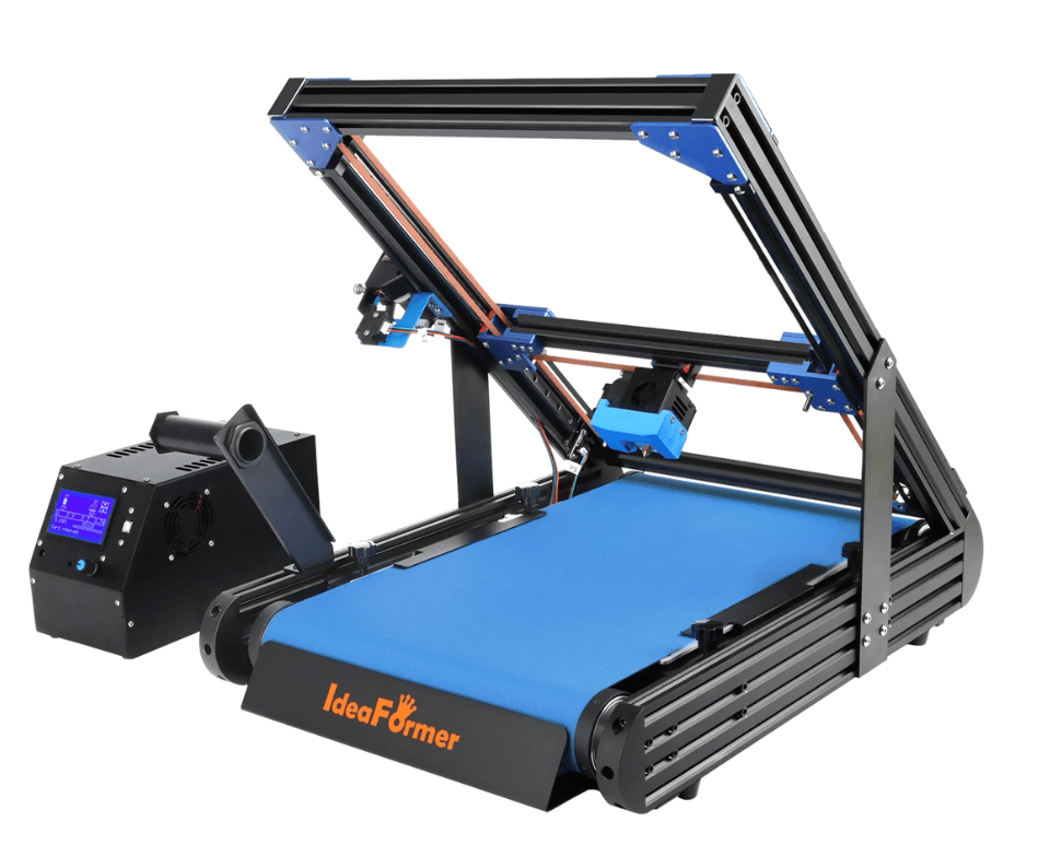
And the second is also for sale, the Ideaformer IR3 V1:
The third one is a DIY printer, the EZ-belt.
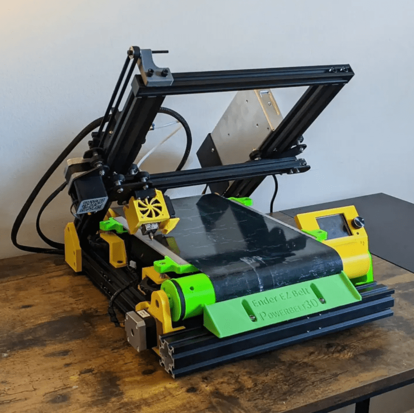
The original Ender EZ-beltThe Opensource Ender EZ Belt is originally based on an Ender3 pro and needs to be heavily modified.
DOWNLOAD the printed parts for the Ender EZ-belt HERE: ender-ez-belt-3d-printer-conversion-model_files
The fourth is my choice for the build: The white knight core xy beltprinter:

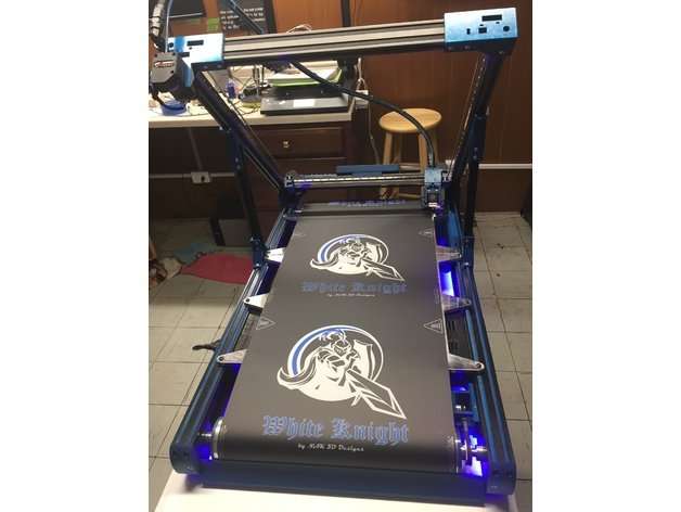
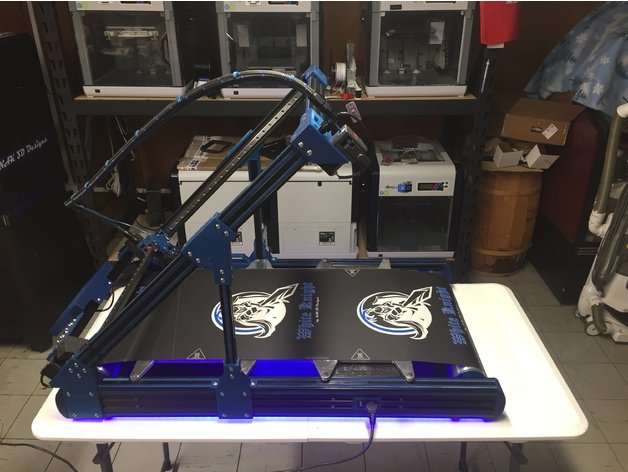

LINK TO THE WHITE KNIGHT WEBSITE and to it’s GITHUB’s repository
All of the hardware like frame parts, extruder, hotend, motherboard, steppers, teethed wheels and -belts, bearings, nuts and bolts are available.
I will go with a Duet2wifi board, since this is known to me and I like the Duet’s web interface a lot. An ESP32 camera will be added to the build and this will also be integrated into the Duet’s Web interface, as with all my other printers.
TO BE SOURCED:
I will need to source a good 24V PSU but I may go with an external one for this build, to start with.
The belt and corresponding heated bed have veen ordered from Ali, I chose an Ideaformer belt , 320mm wide, 1.3 mm thick and a perimeter of 1180mm.
![]()