After I installed the homing switches for X and Y on the E3D toolchanger, I finally had a decent starting point to get the tools pickup and parking tuned.
Originally, I used sensorless homing but this caused changing offset values of the X- and Y positions of the machine. So the tools could not be picked up or brought home consistently after a reset.
Now, everything works fine and the X-Y values don’t change anymore after a reset.
What I did was to first make some macros for a one-off setting of the X and Y postion of the 4 Tools for the toolhead’s positioning. If you don’t do this, you have to change all X values manually in 8 macro’s every time you want to change the value of X.
This was done with a number of global variables. After defining these in a macro, they need to be called before using them. In Config.g, I made a reference to run the macro of the globals.g macro so it runs every time you boot the Duet.
In config.g, after the Tool definitions I added the M98 code to start the global definition of the used variables:
M98 P”0:/sys/globals.g” ; Make global variables in this globals.g macro
This macro file looks like this in my case and please be aware that the actual variables will differ per machine, but this may give you a starting point:
global T0_X_dock=-12.3 ; X-Parking position of Tool 0
global T0_Y_dock=225.2 ; Y-Parking position of Tool 0
global T1_X_dock=80 ; X-Parking position of Tool 1
global T1_Y_dock=225.9 ; Y-Parking position of Tool 1
global T2_X_dock=212 ; X-Parking position of Tool 2
global T2_Y_dock=226 ; Y-Parking position of Tool 2
global T3_X_dock=304.7 ; X-Parking position of Tool 3
global T3_Y_dock=225.4 ; Y-Parking position of Tool 3
The tfree 1-3and the tpre 1-3 files will then be like this for T0, and you can make the others by just fulling in T1 , T2 or T3 where it now states T0:
; tpre0.g
; called before tool 0 is selected
;Unlock Coupler
M98 P”Coupler – Unlock.g”
;Move to location
G1 X{global.T0_X_dock} Y200 F50000 ; was X-10.5
;Move in
G1 X{global.T0_X_dock} Y220 F50000
;Collect
;G1 X{global.T0_X_dock} Y229.2 F1000 ;was f2500
G1 Y{global.T0_Y_dock} F1000
;Close Coupler
M98 P”Coupler – Lock.g”
;WARNING! WARNING! WARNING! WARNING! WARNING! WARNING! WARNING! WARNING! WARNING! WARNING! WARNING! WARNING!
;if you are using non-standard length hotends ensure the bed is lowered enough BEFORE undocking the tool!
G91
G1 Z10 F1000
G90
;Move Out
G1 X{global.T0_X_dock} Y150 F10000; was 4000
And I made some macros for checking where the toolhead is positioned, right in front of the tools T0-T3:
; fit_T0.g
; called to fit the Tool just in front of the dock
G91
G1 Z4 F1000
G1 Y-10 F2000
G90
G53 G1 X150 Y100 F20000
;Move In
G53 G1 X{global.T0_X_dock} Y150 F10000
G53 G1 X{global.T0_X_dock} Y200 F10000
G53 G1 X{global.T0_X_dock} Y220 F10000
If you want to check wether you made the correct changes to globals.g, be aware that the new values in the globals.g variables macro will only be read when you reboot. [If you want to redefine the values in any other way without rebooting, you will need another type of call function.]
My E3D toolchanger appeared to have some small inconsistencies in homing X and Y.
This became apparant after I tried to tune the exact positions of the tools pickup, after having homed.
Every time it was tuned, it worked well and the next day it was just a bit off. Then I retuned it again, and after a day it was off again. Not a lot, but just 0.1 mm or a bit more. But it did cause problems with the toolchanges.
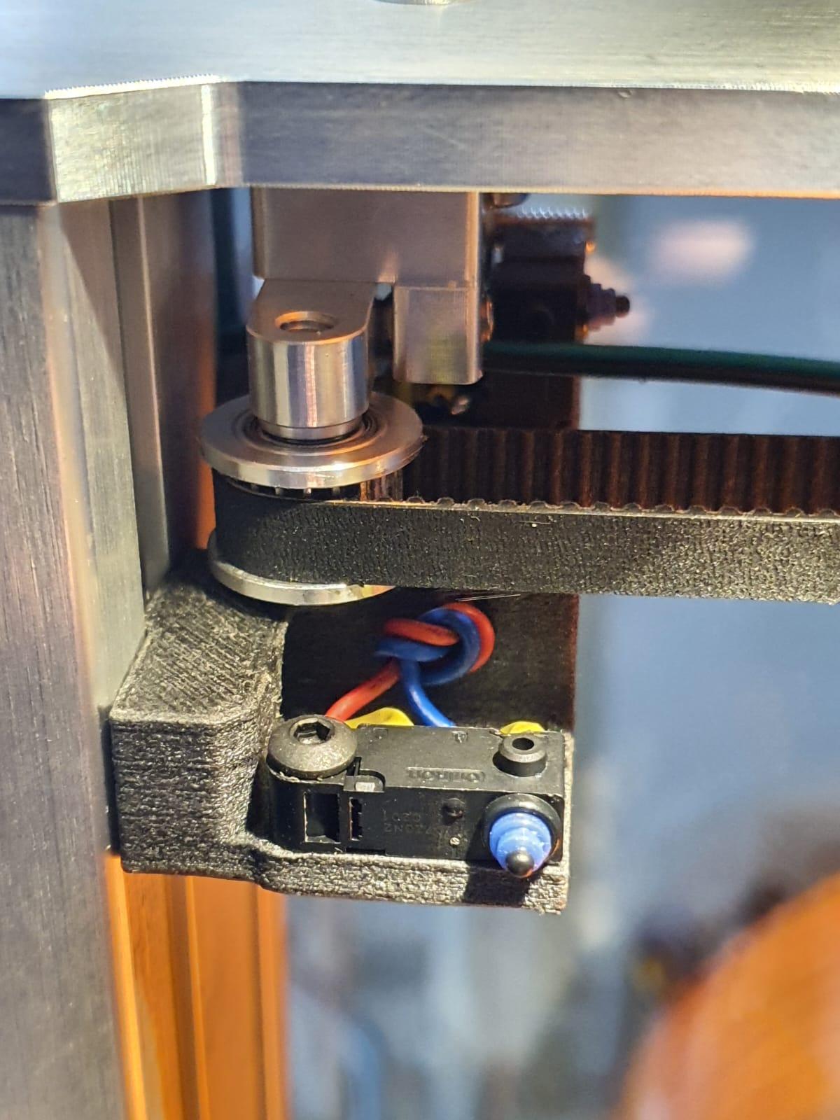
So- after reading a bit I found that others had this problem as well and produced a solution: Just put in a couple of good X- and Y homing switches!
I even found the to be printed 3d-parts for mounting these switches. Thanx for this, folks!
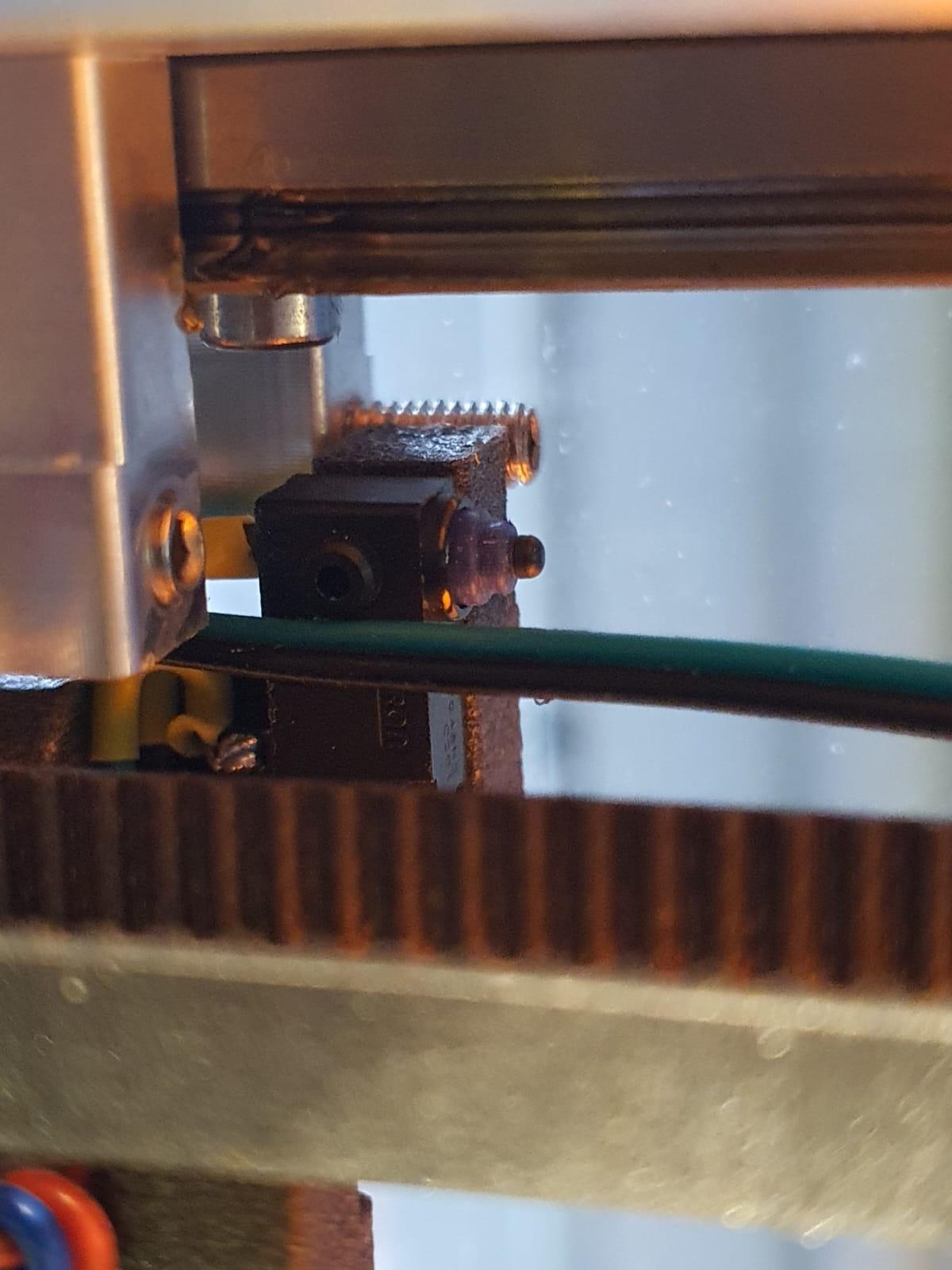
The switches are the same type as for the Z-switch.
X-axis end switchY-axis end switch
I printed the mounts in PETG carbon on my Prusa mini and mounted both switches on the E3D toolchanger.
After this, I amended config. g and the homing files, please see the rest of my post for this:
CONFIG.G CHANGES
; Endstops
M574 X1 S1 P”xstop” ; X min active high endstop switch
M574 Y1 S1 P”ystop” ; Y min active high endstop switch
M574 C0 ; no C endstop
M574 Z0 P”nil” ; no Z endstop switch, free up Z endstop input as Z endstop switch. (I changed this part for correct working with RRF3.3+)
NEW HOMING FILES:
; homex.g
; called to home the x axis
M98 P”homey.g” ; Home Y always before homing X
G91 ; use relative positioning
G1 H2 Z3 F5000 ; lift Z 3mm
G1 H1 X-400 F15000 ; move left 400mm, stopping at the endstop
G1 X5 F15000 ; move away from end
G1 H1 X-400 F2000 ; move left 400mm, stopping at the endstop
G1 X2 F2000 ; move away from end
G1 H2 Z-3 F1200 ; lower Z
G90 ; back to absolute positioning
; homeall.g
; called to home all axes;
M98 P”homec.g” ; Home C (ToolHead)
M98 P”homex.g” ; Home X
M98 P”homez.g” ; Home Z
G1 X150 Y-49 Z20 F15000 ; Park
; homey.g
; called to home the Y axis
G91 ; use relative positioning
G1 H2 Z3 F5000 ; lift Z 3mm BED DOWN
G1 H1 Y-400 F15000 ; move to the front 400mm, stopping at the endstop
G1 Y5 F15000 ; move away from end
G1 H1 Y-400 F2000 ; move to the front 400mm, stopping at the endstop
G1 Y2 F2000 ; move away from end
G1 H2 Z-3 F1200 ; move Z BED UP
G90 ; back to absolute positioning
Z homing did not change and remains as is:
; homez.g
; called to home the Z axis
M98 P”Coupler – Unlock.g” ; Open Coupler
G91 ; Relative mode
G1 H2 Z5 F5000 ; Lower the bed
G90 ; back to absolute positioning
G1 X150 Y100 F50000 ; Position the endstop above the bed centre
M558 F1000 ; speed to 1000
G30 ; probe x 1
M558 F300 ; speed to 300
G30 ; probe x 1
The toolhead stepper of my E3D toolchanger system suddenly broke down.
The cause was a failed tool pickup move, due to which the rotating axle of the toolhead pickup system got blocked.
After exchanging the stepper I changed the Duet’s settings so the C-drive will not be able to generate too much torque.
This will prevent the last teethed wheel to break whenever the driven pickup axle gets blocked under extreme circumstances.
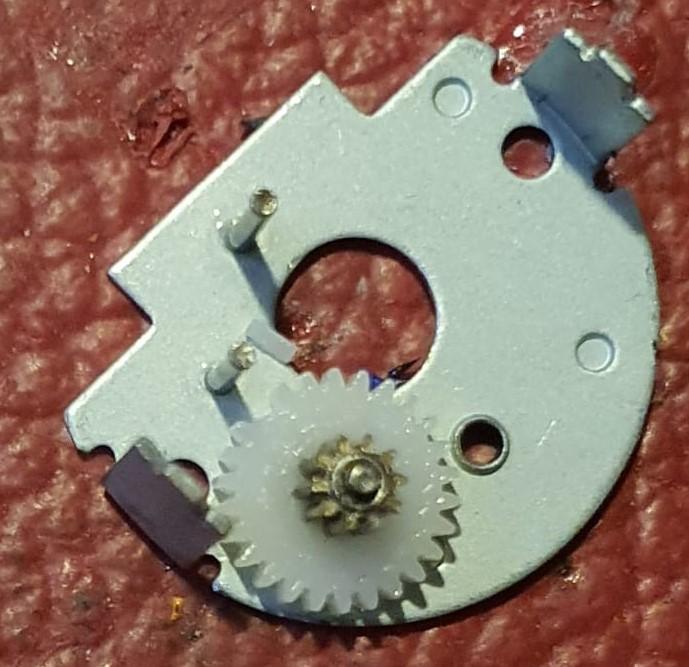
After opening the case of the failed reduction box, I discovered 1 broken tooth of the final gear.
I ordered me a new one, and mounted this. And I changed the C-drive’s settings to make use of the stall mechanism. It took some tweaking to get this to work properly. After all, picking up a tool must still work as this is the base intention.
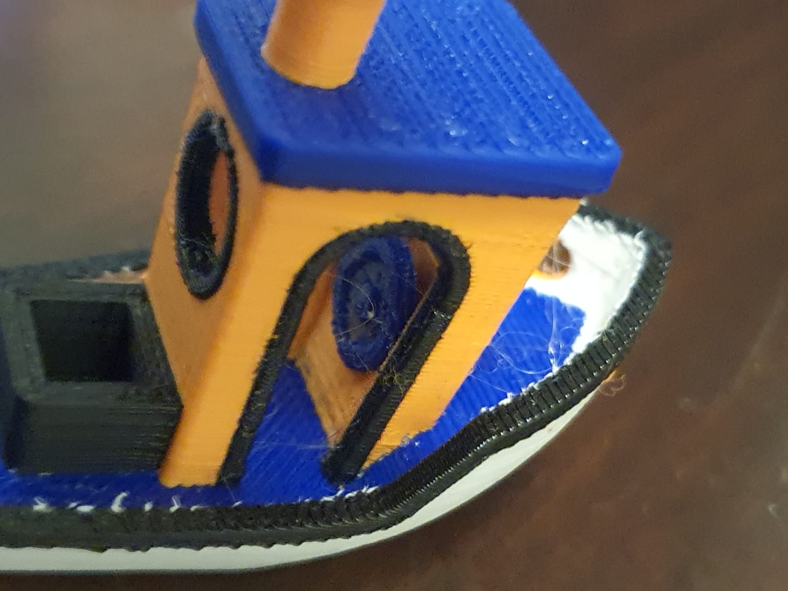
In the end, the solution to my intermittent on/off problem with my toolfans on the Hymera direct drives was extremely simple.
The picture shows the solution, as the Hymera stepper driver obviously interferes with the 40mm fans. The problem was that these fans 2,4,6 and 8 not always started spinning.
I tried to exchange the fans which did not help, tested the Voltage, current , settings and so on. Everything appeared to be OK.
Strangely enough, when testing the fan off the Hymera tool, even including the duct attached, everything woked fine. Just did not work when mounted on the Hymera.
Finally, Just trying some things, I pushed a thin steel plate (NOT RVS) in between the fan and the stepper motor, and now it always works, even at 5% PWM! Problem solved!
After testing at all tools, I made 4 better fitting thin plates and mounted these at the 4 tools and no problem exists anymore, ever since!