I have driven my BYD Atto 3 from its purchase in November 2022 with a Garmin mini dashcam mounted in it, on the windshield just above right next to the interior mirror. That works fine, except you have a cable running that you have to get rid of and you have to use your phone app to view the footage.
According to the BYD dealer, it is not possible to retrofit the original BYD dashcam.
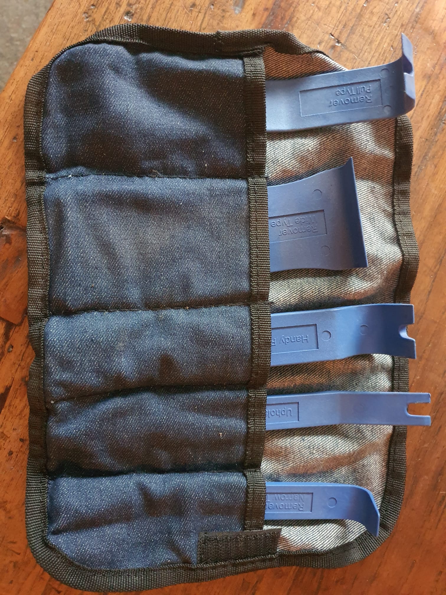
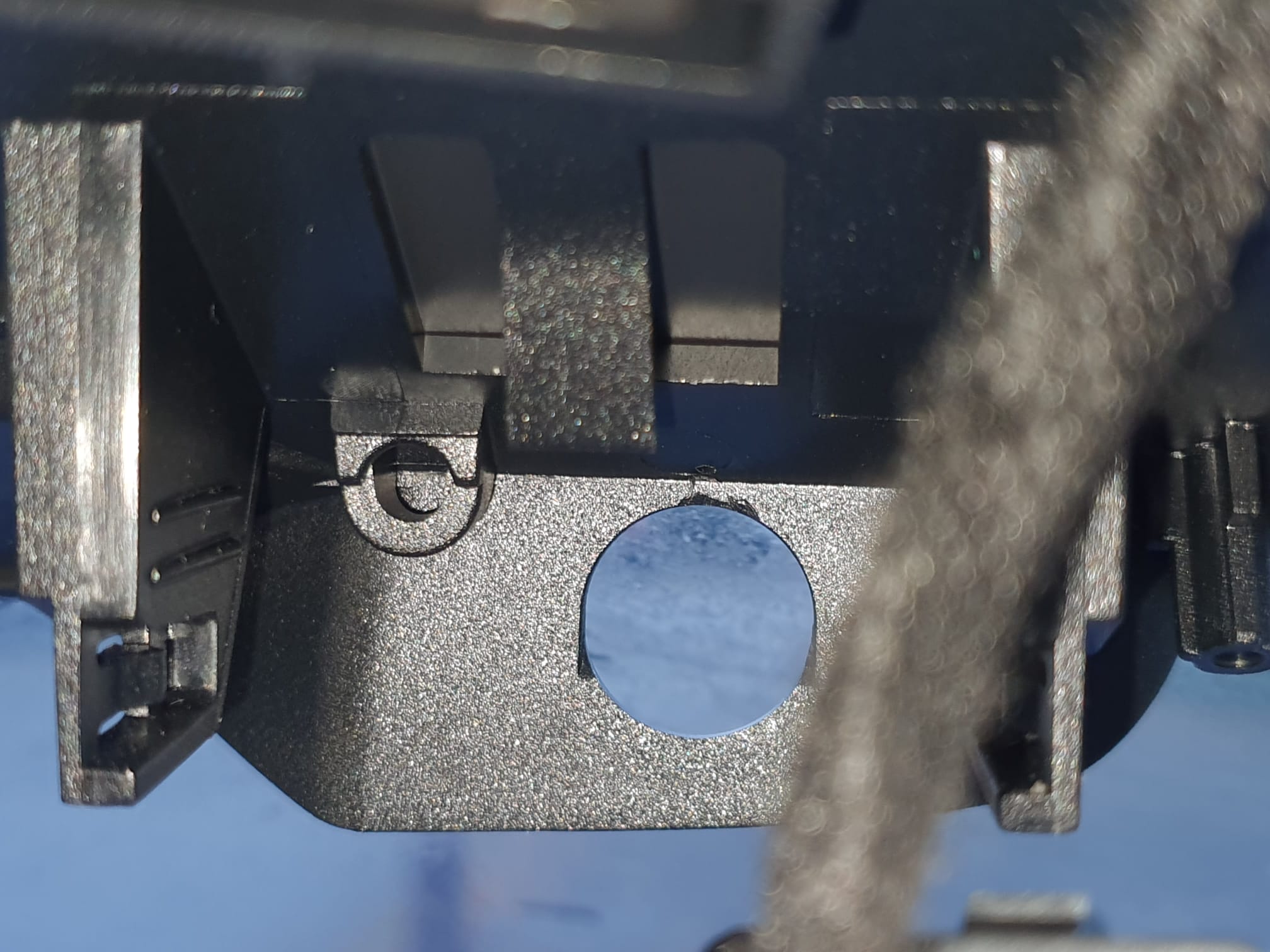
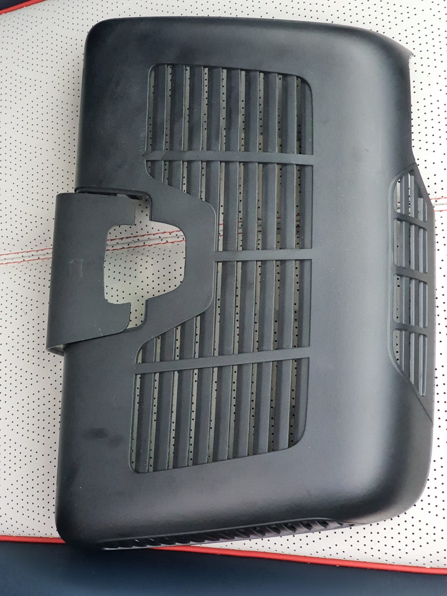
I removed the protective cover where the dashcam should go in, using appropriate tools for this purpose so as not to damage the plastic snap brackets.
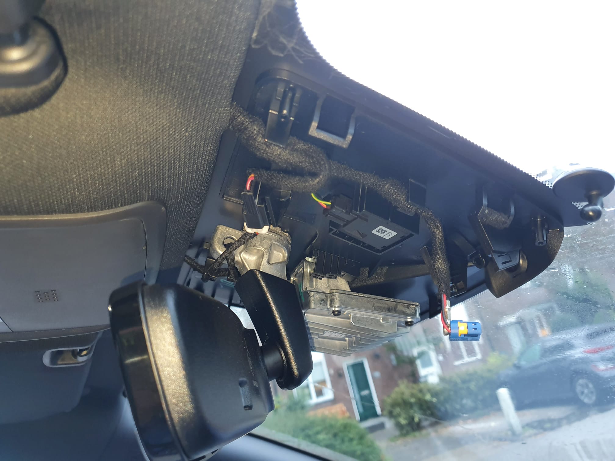
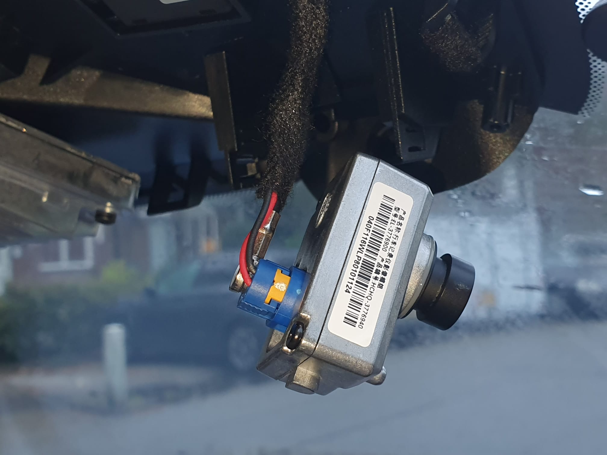
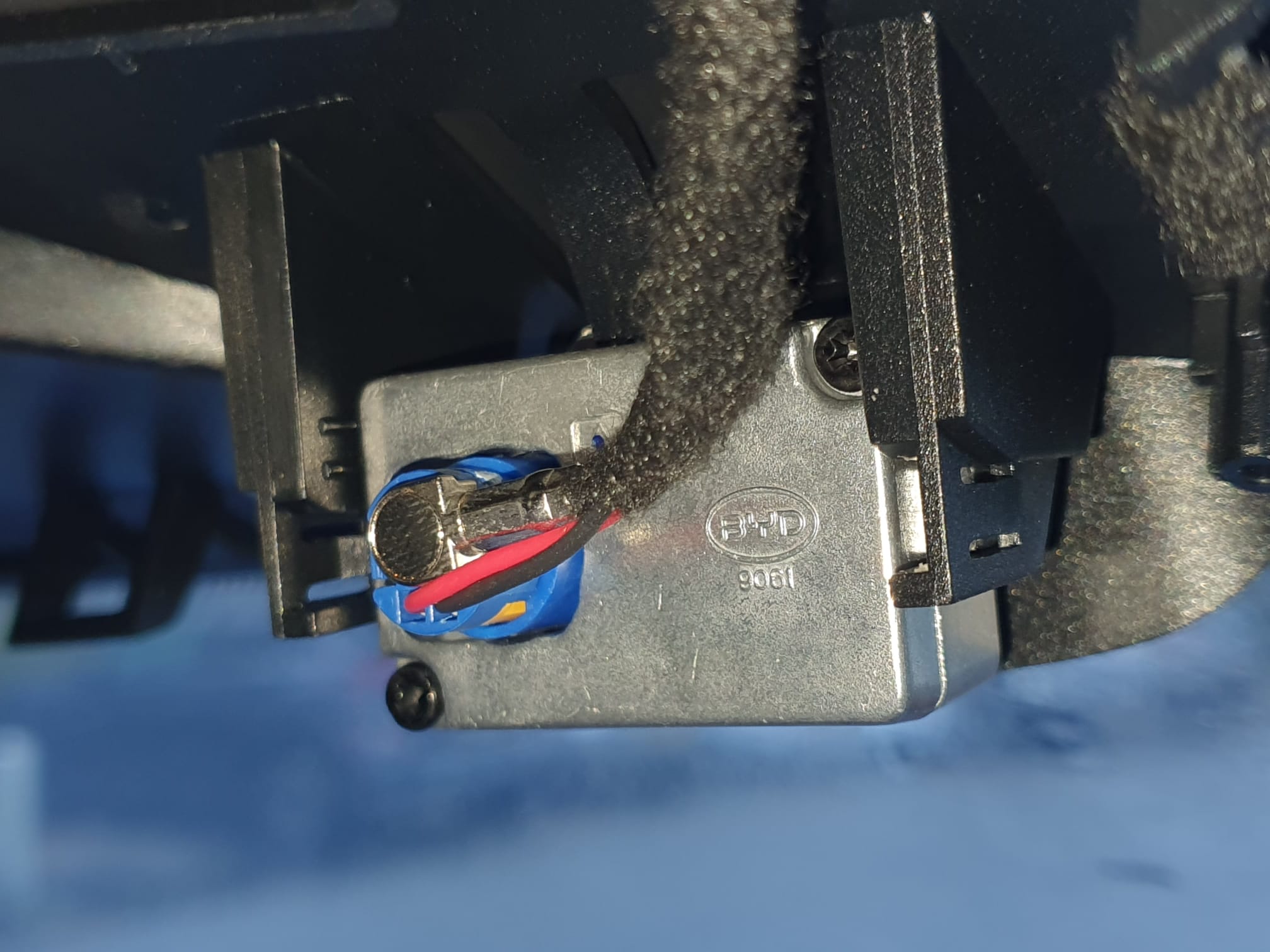
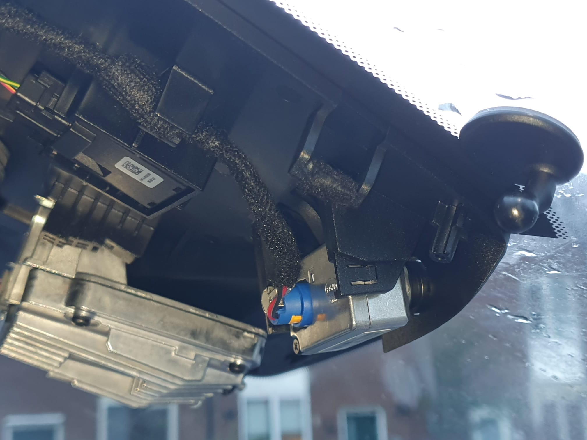
It then turned out that the cable for the dashcam is just neatly mounted there. On the right side of the picture below, you can just see the mounting foot of the Garmin mini dashcam. The blue loose connector with yellow area is the connector for the original BYD dashcam. Obviously, this is for a left-steered version but for a right-steered version the situation is just mirrored.
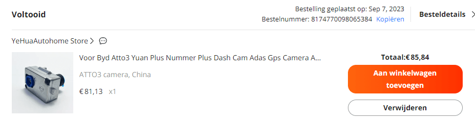
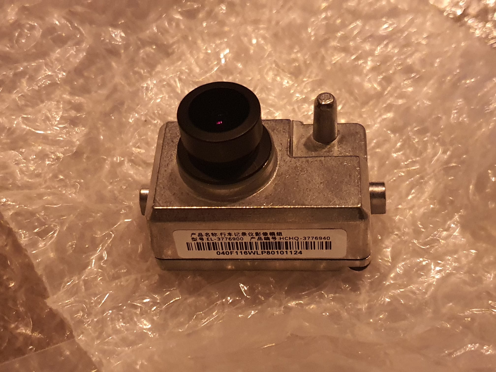
On Aliexpress I just came across the original BYD dashcam as a separate replacement unit, for about 83 Euro. So ordered it 2 weeks back and mounted it this morning.
Mounting is very simple: First remove the rubber where the lens of the dashcam should come through .
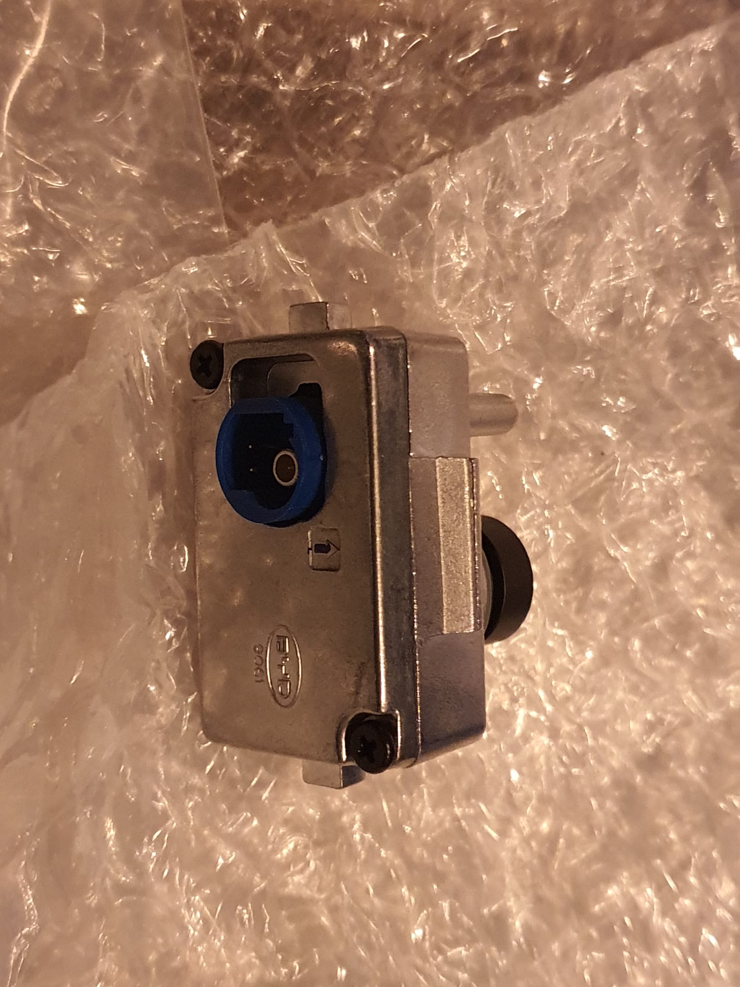
Then click the cable into the camera, it is automatically secured. Look very carefully how to insert this plug! It is a combined plug with 2 contacts for the power supply and a coax video connector attached to each other so it only fits one way!
And click the camera in the right place in the holder.
And…guess what? It just works. I also simultaneously had the update of the car to V 1.4 underway, and after booting up, the car detected that a dashcam was present. And the app was activated right away, so the camera now functions integrated into the car!
I then mounted the protective cover and neatly removed the Garmin dashcam mounting sticker and cleaned the windshield. When reinstalling the protective cover, I placed the large part first. Then turned the mirror down under and inserted the small part into the large part. That took some very careful work…
.
The software is self-explanatory: you do need to insert a MicroSD card under the dash. I have a 128Gb MicroSD card in there and I formatted it to FAT32 via the car software’s camera app.
What you find after using the camera is a number of directories on the microSDcard. your files are in the DCIM folder, arranged by video and photo.
The app allows you to change a number of settings including the recording time per recorded clip. I always set that to the longest possible time, here it is 5 minutes. just like the Garmin.
You can watch live and then also take pictures. I have programmed a quick button on the steering wheel to allow the dashcam to take recordings when I feel it is important. Of course, the app always makes recordings anyway, which are kept for a short time because of the size of the storage on the MicroSDCard. when the card is full, the oldest recordings go off. But when you initiate a recording yourself then this recording is always saved on the MicroSDCard.
Programming the camera power button for protected (non-erasable) recordings) goes like this: You use the screen rotation button on the steering wheel for this purpose. Press this button for 5 seconds until the large LCD screen gives you the choice of what you want to connect to this button. So I chose video recording for this.
If you want to copy recordings, the easiest way is to copy them to a USB drive via the file manager app of the BYD software. just copy from MicroSDCard/DCIM/…. to USB/… paste like on your phone.
That’s it! Have fun with your dashcam in the BYD Atto 3.
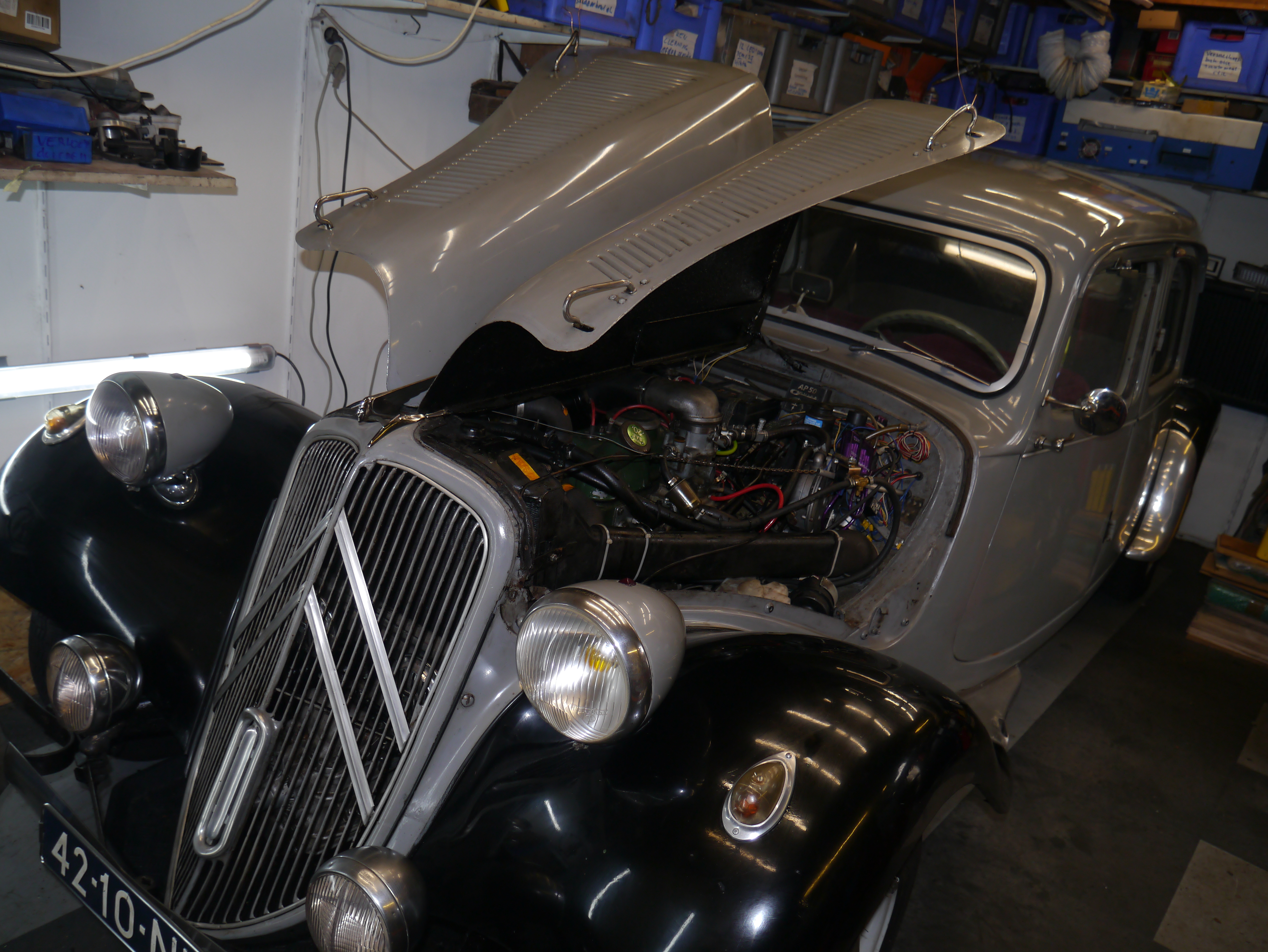
De Traction Avant doet het weer NA DE REPARATIE 28-9-2023:
LEES ONDER VERDER
voor het verslag over het gesperd differentieel:
de oorzaak, de oplossing en de aanpak:
DAG 1
Al een tijdje deed mijn cruise control het niet dus wilde ik dat repareren.
Daarom heb ik de onderste veerarm van het linker voorwiel op een bok gezet, met het wiel net vrij. Vervolgens heb ik de sensor van de cruise control goed afgesteld op de magneet die op de aandrijfas-flens van het linker voorwiel is gemonteerd.
Vervolgens de motor gestart en het linker wiel laten draaien om te checken of alles nu goed werkt. Dat heb ik op verschillende snelheden gechecked omdat de cruise control pas vanaf ca. 50 km/uur begint te werken. Maar de wagen bokte opeens na een paar keer uitproberen. Ik heb snel de koppeling ingetrapt en de motor afgezet.
Daarna wilde ik het linker wiel even met de hand draaien en daarbij merkte ik dat het wiel niet meer kon bewegen. Kan natuurlijk gebeuren, als een versnelling is ingeschakeld. Maar ik doe dat nooit. Ik parkeer in de garage altijd met de versnellingsbak in neutraal, omdat ik de auto nog weleens wat wil verplaatsen.
Dus – even checken en de bak stond gewoon in neutraal. Dat is gek. Andere wiel opgekrikt en beide kanten op de bok. Het wiel draait nu prima, alleen draait het andere wiel gewoon mee als ik aan het linker wiel draai. En dan nog wel in dezelfde richting. Oeps.
Opeens was ik helemaal niet meer bezig met de cruise control, maar zag ik visioenen van een complete versnellingsbakrevisie. Of tenminste het differentieel, in het bijzonder de satelliet- en planetaire wielen. Maar dat kan toch zomaar niet?
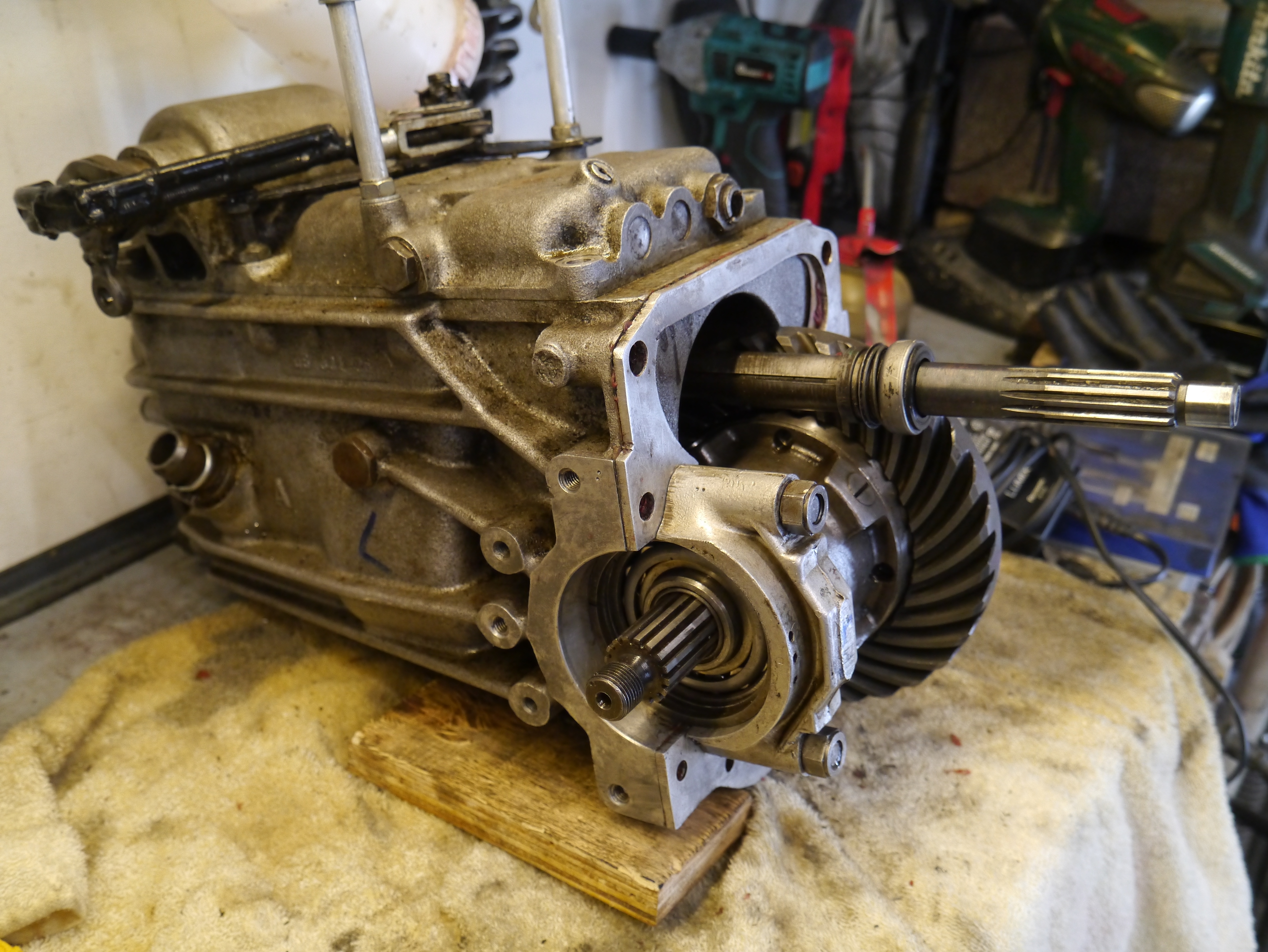
Om er achter te komen zit er natuurlijk maar één ding op: Het differentieel uit elkaar halen en zien wat er aan de hand is.
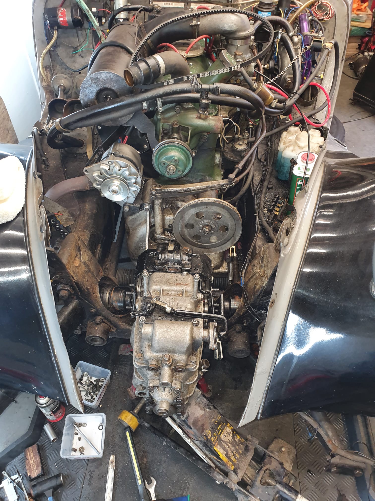
Klinkt gemakkelijk, maar bij mijn Traction Avant is geen gewone 3-bak gemonteerd, maar een Citroen ID 4-bak (langeslag motorversie), samengebouwd met een koppelingshuis van een Traction Avant. Dat was al een behoorlijk klusje, dus eruit en hopelijke er snel weer in gaat even tijd en moeite kosten.
Maar OK, ik heb het al een paar keer eerder gedaan dus gewoon beginnen en we zien wel.
Dus even nadenken.. het is al een aantal jaren terug dat ik de 4-bak heb ingebouwd, even op mijn website kijken hoe ik dat ook al weer deed…
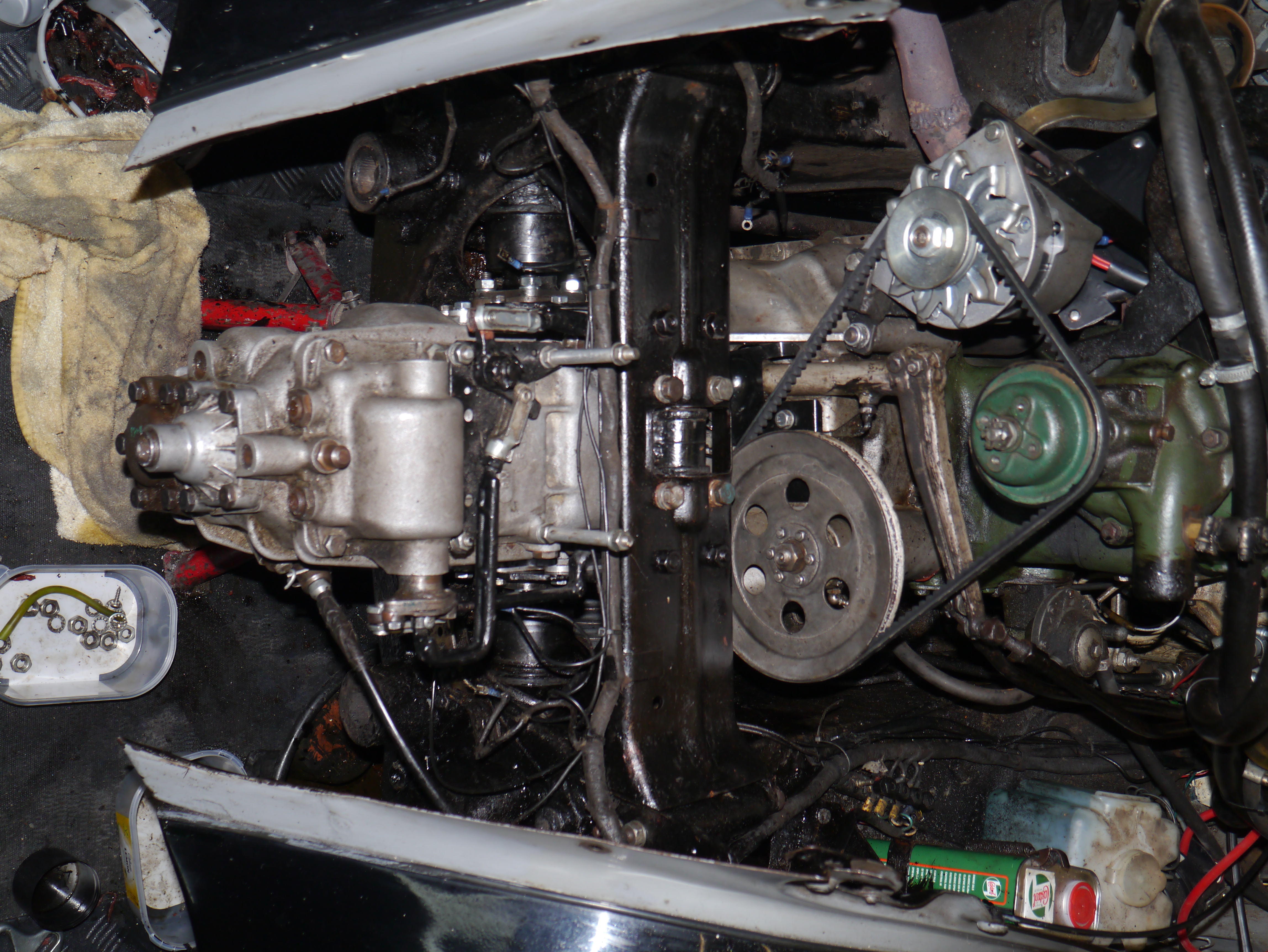
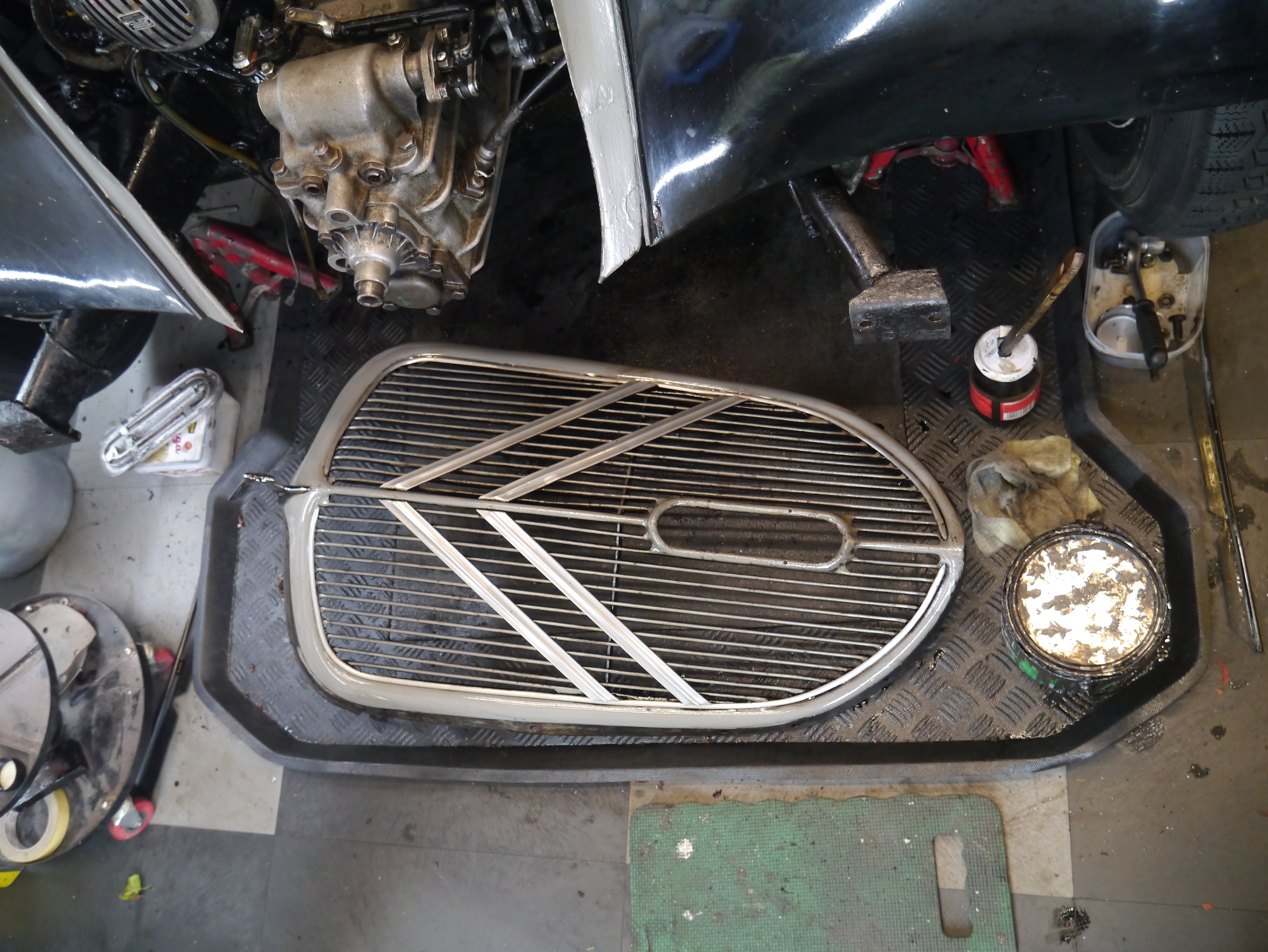
Dus in deze volgorde demonteren: 1) Motorkap, 2) grille, 3) voorbumper, 3) toeters, 4) kabelboom, 5) radiateur, 6) dynamo-aandrijfriem, 7) schutbordje versnellingsstangen, [ nu de krik en/of support eronder], 8) ophangbrug versnellingsbak/aggregaat, 9) ophangbeugel versnellingsbak en beide schakelstangen (afneembaar en specifiek voor dit type versnellingsbak gemaakt) ,
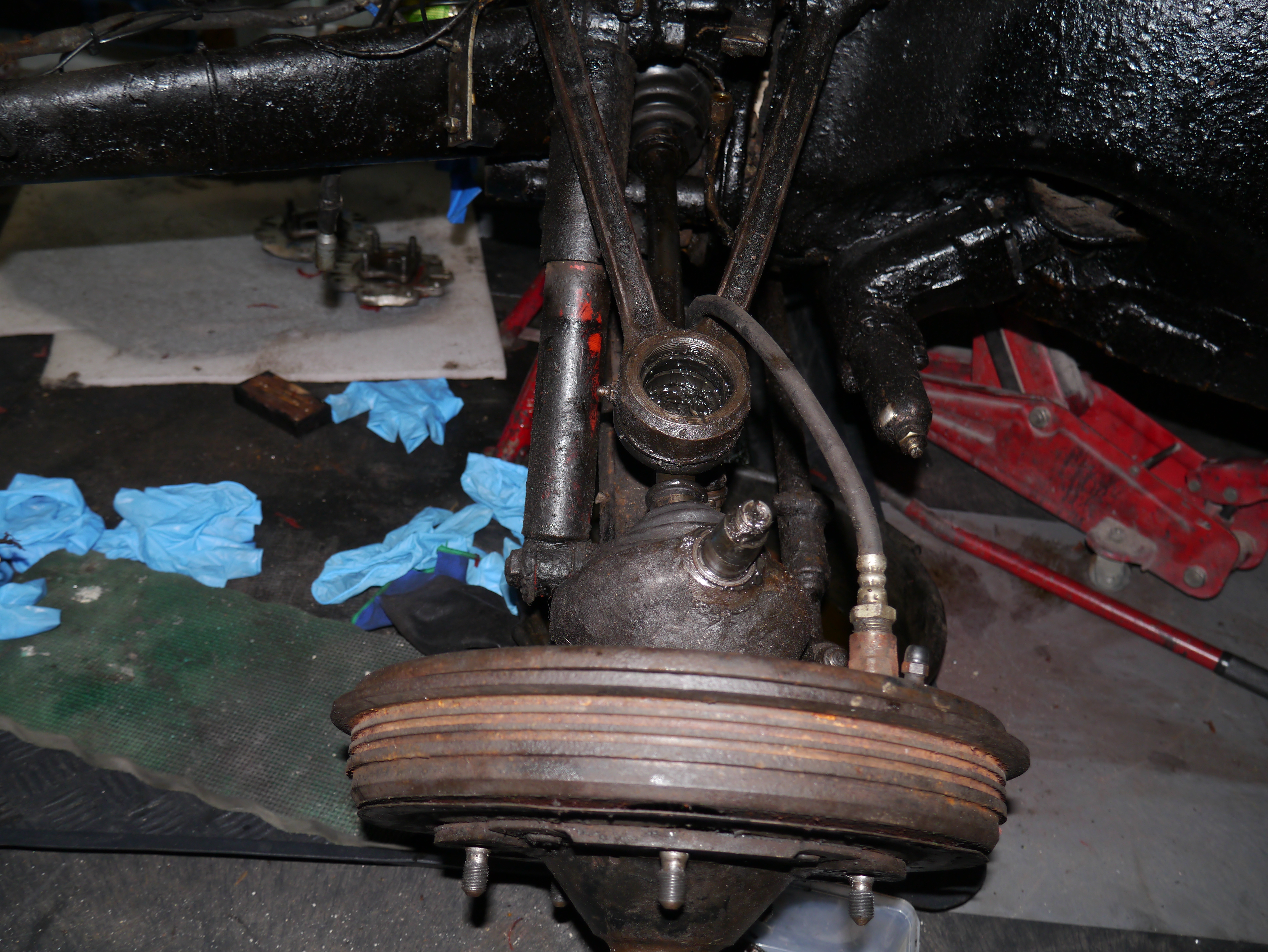
10) linker wiel bovenste fusee lossen,
11) linker wiel flex remslang lossen,
12) asflenzen van bak losmaken 13) opkrikken bak ca 10-15 cm zodat er ruimte is om de flanges te verwijderen,
14) asklauwtjes uitpersen met speciale pers, hierdoor komen de flanges naar buiten uit de bak,
15) bak losmaken van koppelingshuis en demonteren,
16) Differentieel uit bak halen [alles per kant merken en in 2 aparte links/rechts gemerkte bakjes opruimen, anders moet alles opnieuw worden ingemeten en -gesteld],
DAG 2
17) differentieel demonteren….
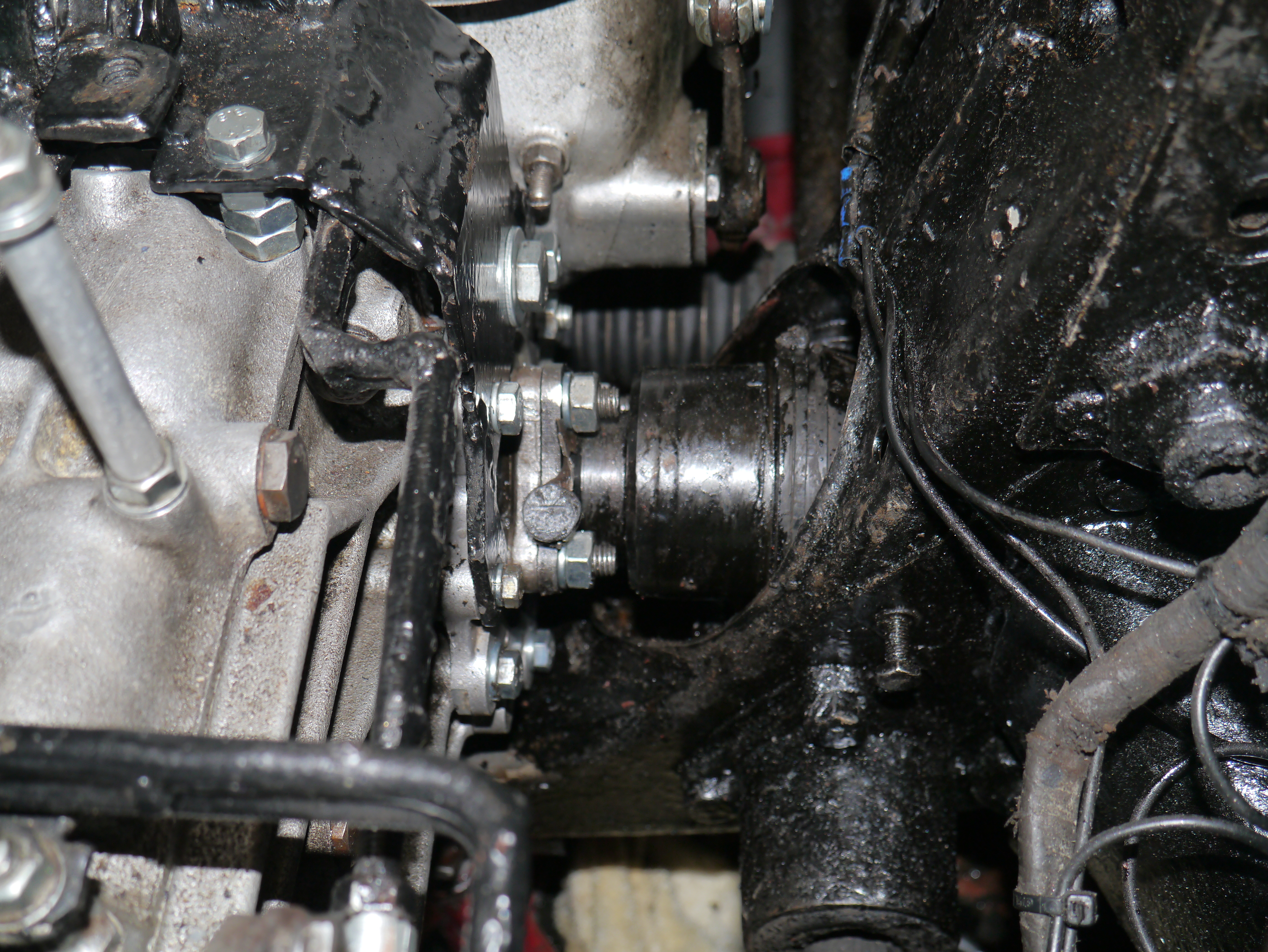
En daar zat de fout. Bij het demonteren van het differentieel bleek de pasbus die ik ooit had gemonteerd in het ID-kroonwiel om de uitgaande as van de TA te geleiden, vast zat om de uitgaande as en kennelijk geprobeerd had om te bewegen in het kroonwiel.
Het lijkt er op dat er onvoldoende vrije ruimte zat in de binnenkant en te veel aan de buitenkant. Ik heb destijds die pasbus uit de vriezer gehaald en in het in de oven verwarmde kroonwiel geplaatst maar dat is geen garantie voor succes gebleken.
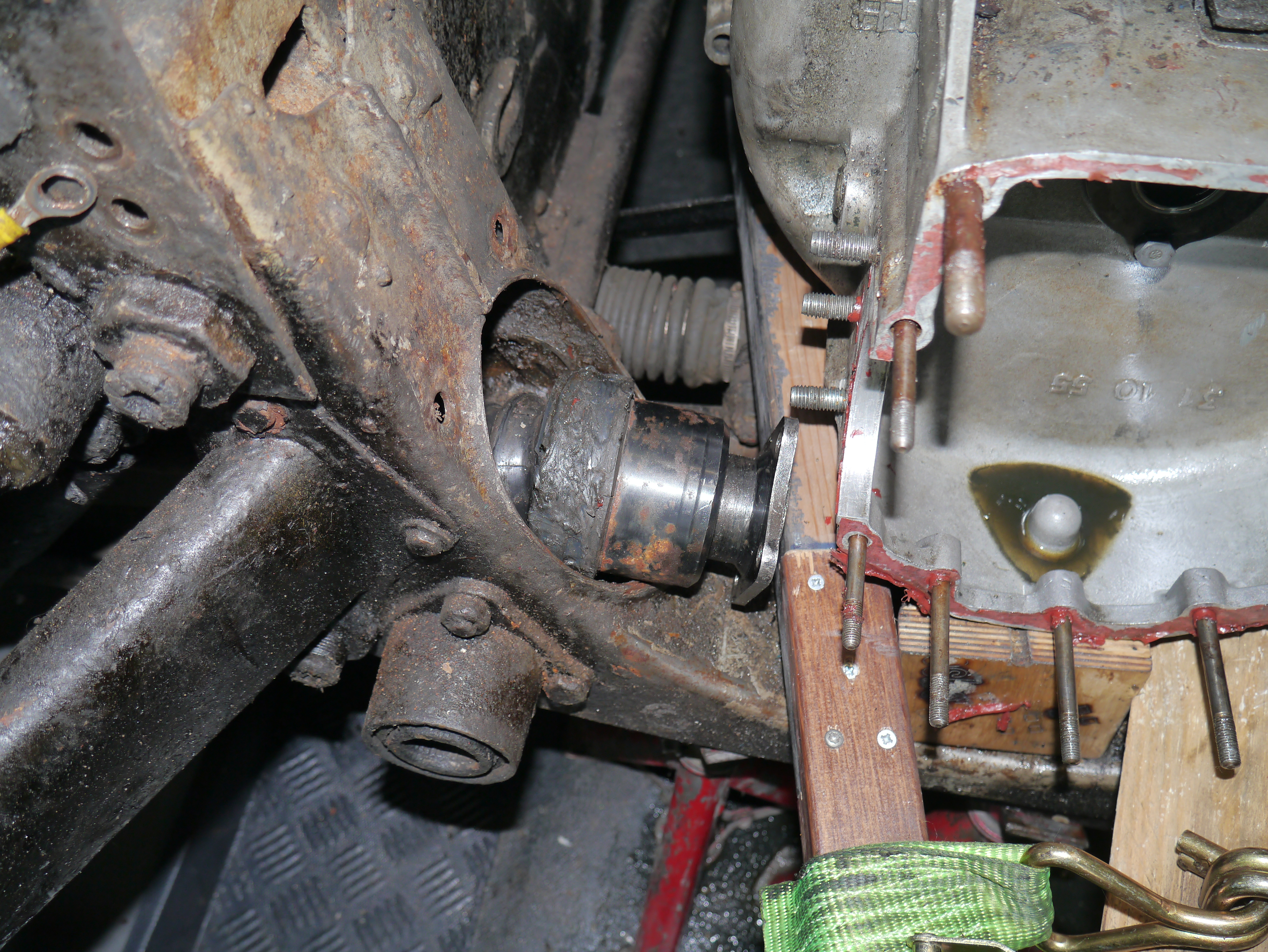
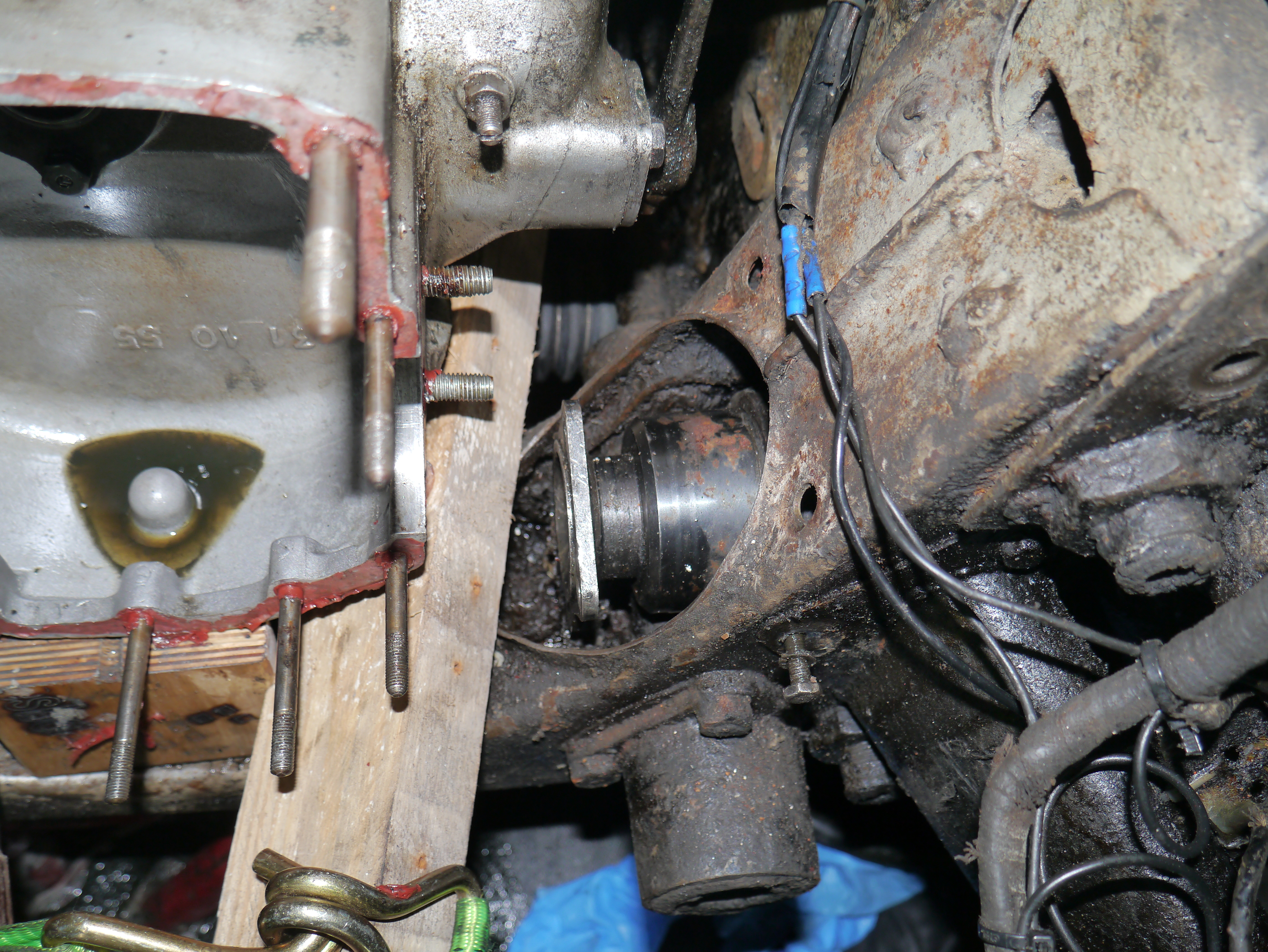
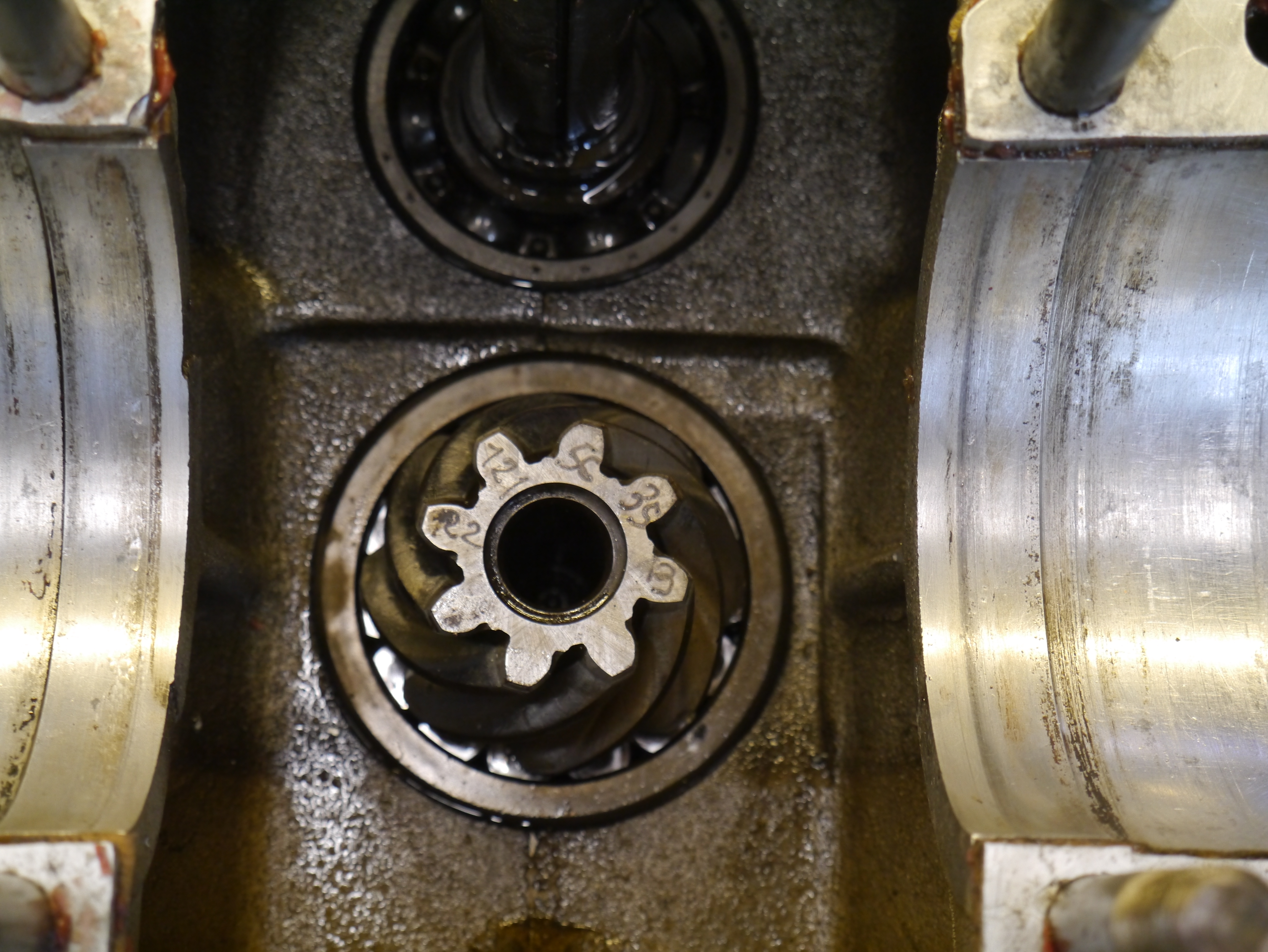
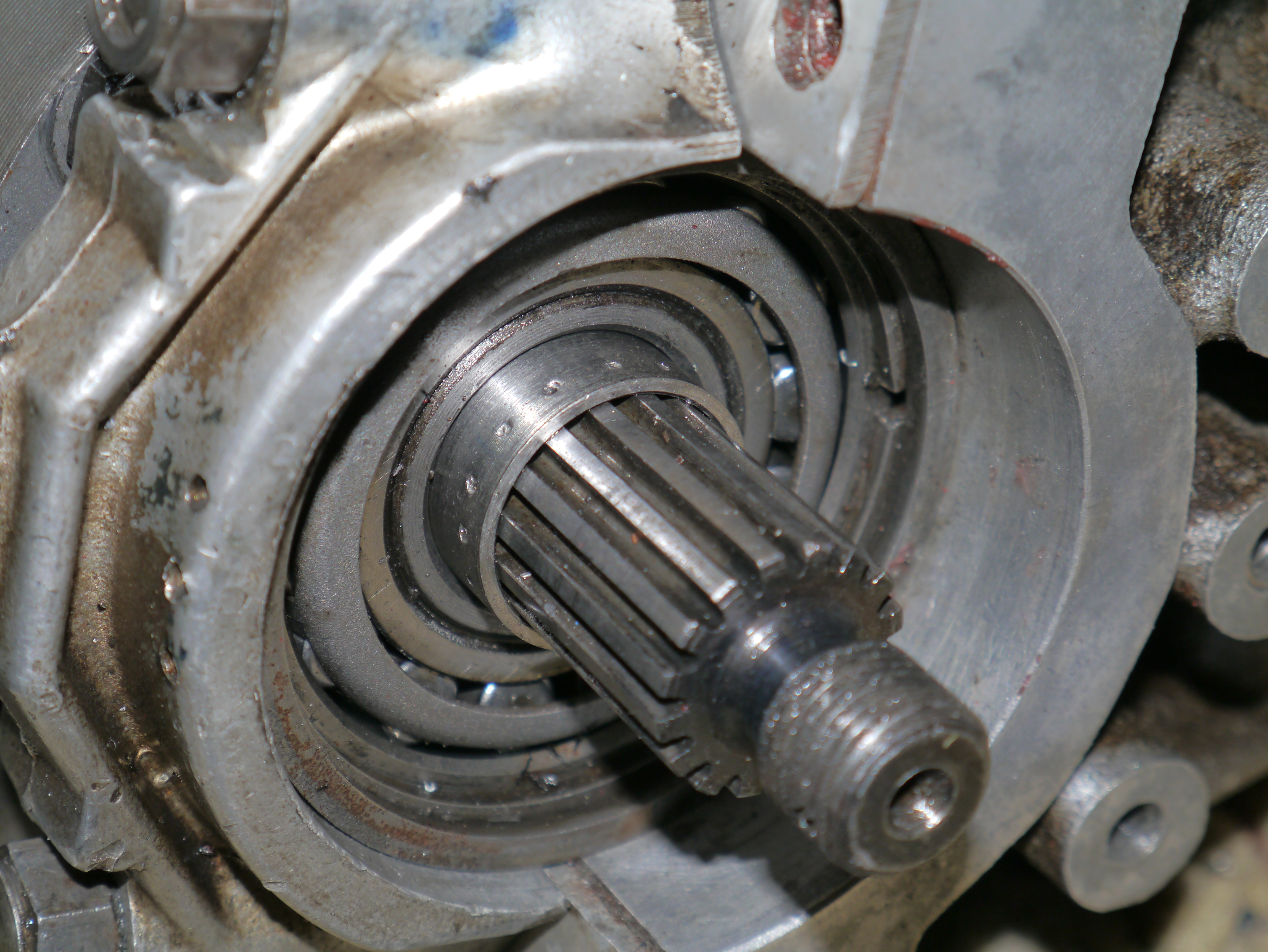
Na het uitpersen van as en bus uit het kroonwiel blijkt de schade oppervlakkig. De buitenkant van de pasbus is het meest gehavend,
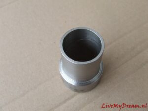
De binnenkant van het kroonwiel waar de as doorheen moet heb ik gehoond en de as met bus heb ik afgedraaid.
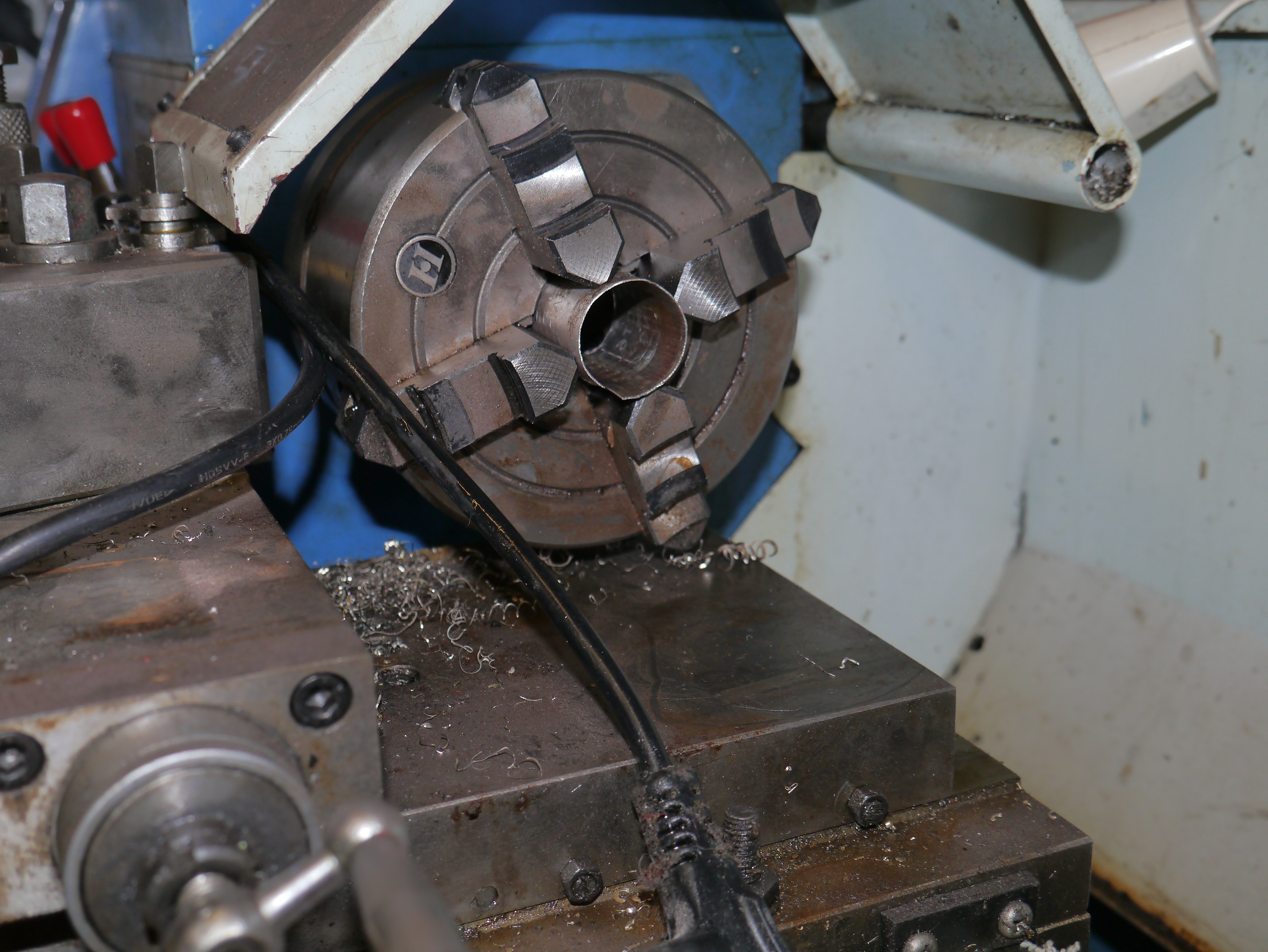
Dat afdraaien was nog wel een klusje want met de drieklauw op de draaibank kreeg ik het niet gecentreerd, ook niet met een vulbus. Dus de 4-klauw gemonteerd en ook met vulbus tegen eventuele schade om de spiebaan van de as heen, netjes gecentreerd midden op de as.
Daarna 0,14 mm in diameter afgedraaid, opgezuiverd met 1600 schuurpapier en olie erop. Het paste prima, zonder olie kun je de as net heen en weer bewegen. Met versnellingsbakolie dempt dat bewegen zodat je het net niet meer voelt. De dikke olie loopt er wel doorheen , zelfs in koude toestand loopt de olie door naar het binnenste deel waar de fiber ring tegen het kroonwiel aan ligt.
Dat is fijn! Nu nog even alles weer monteren!
Van deze fase heb ik destijds geen aantekeningen of detailfoto’s bewaard, en nu weer niet. Dan ben ik gewoon te veel bezig met wat ik aan het doen ben en zit fotograferen er niet in. Gelukkig heb ik nu alles wel onthouden en typ ik het dan maar voor een volgende keer in.
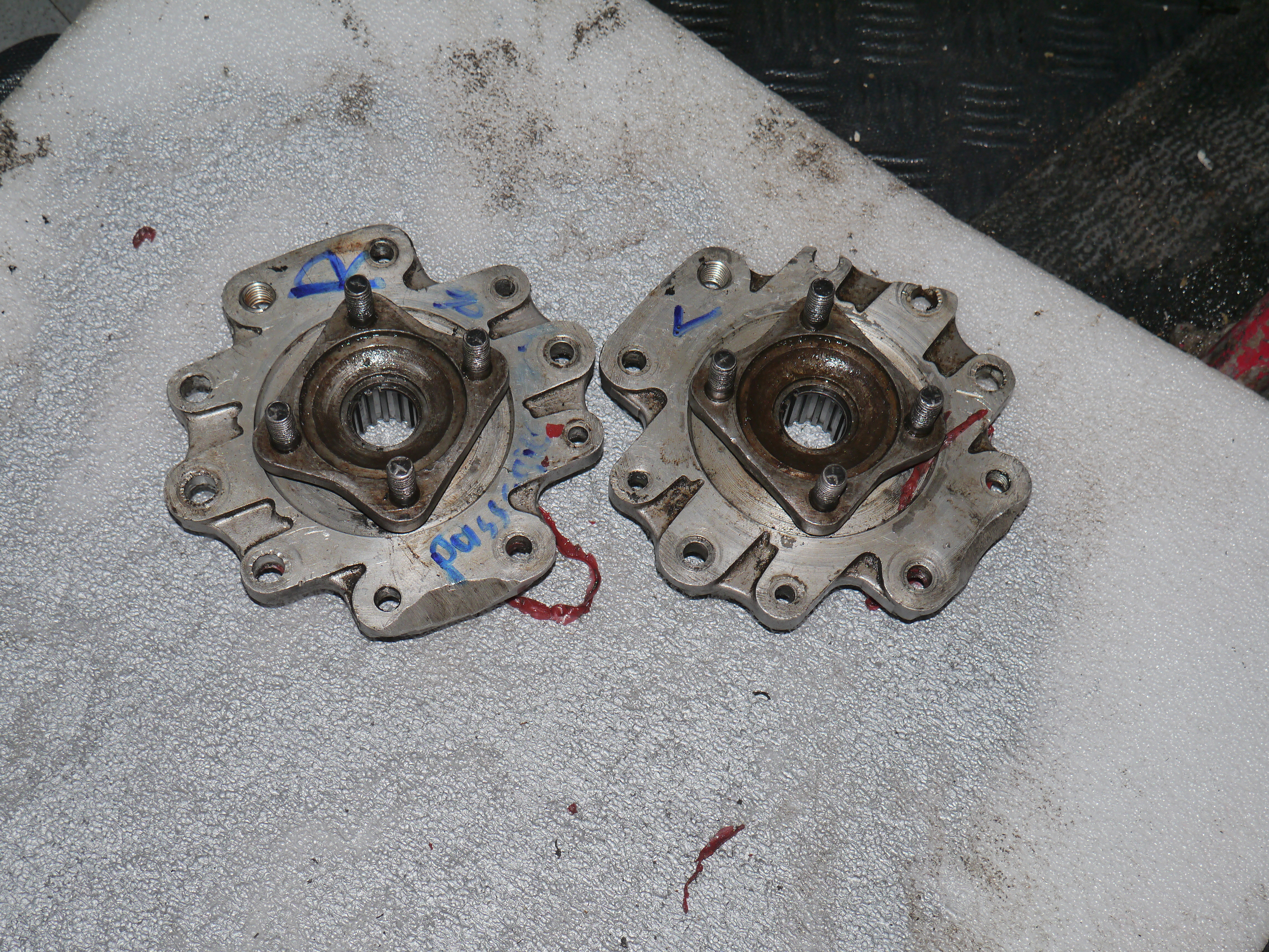
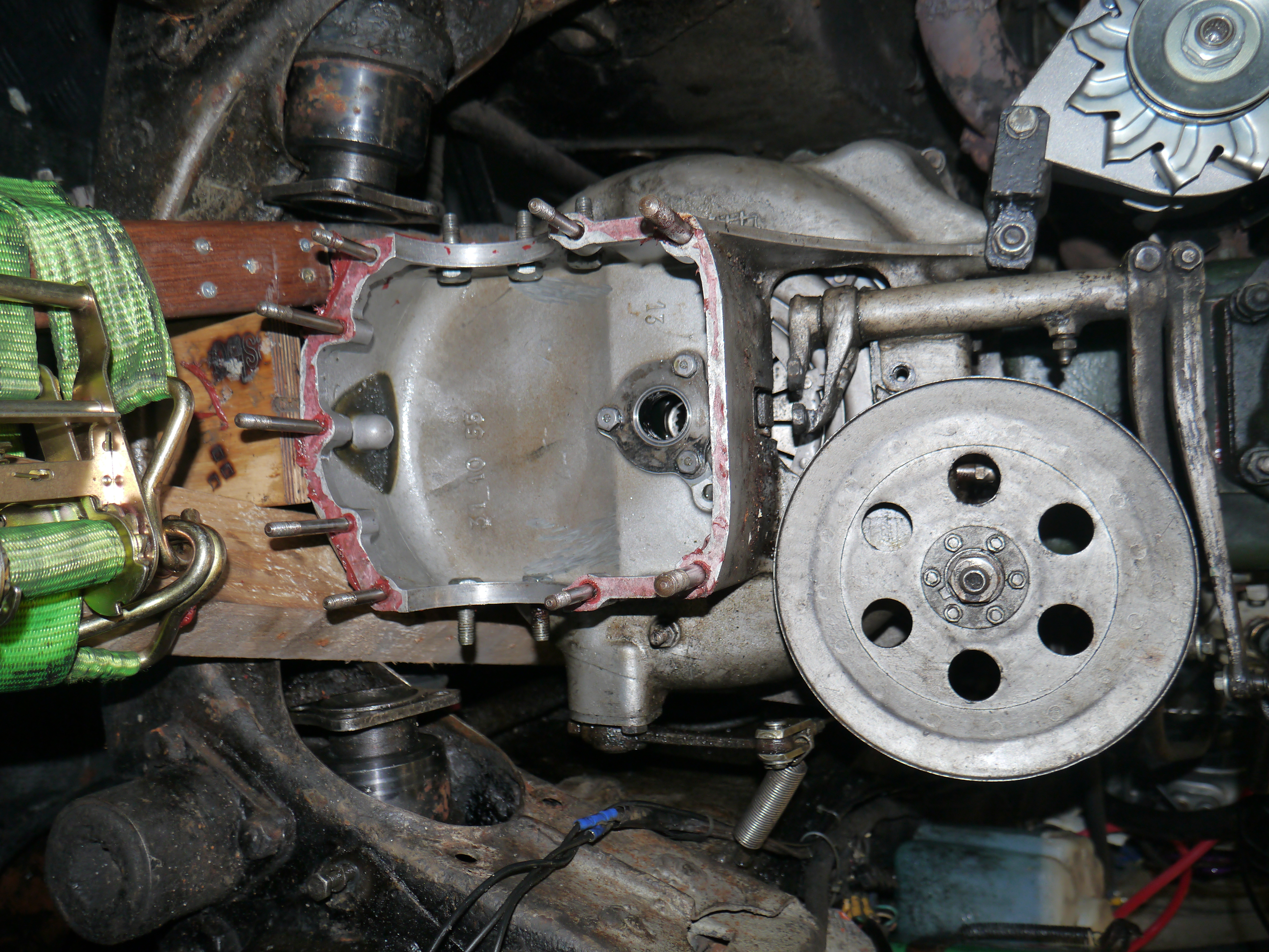
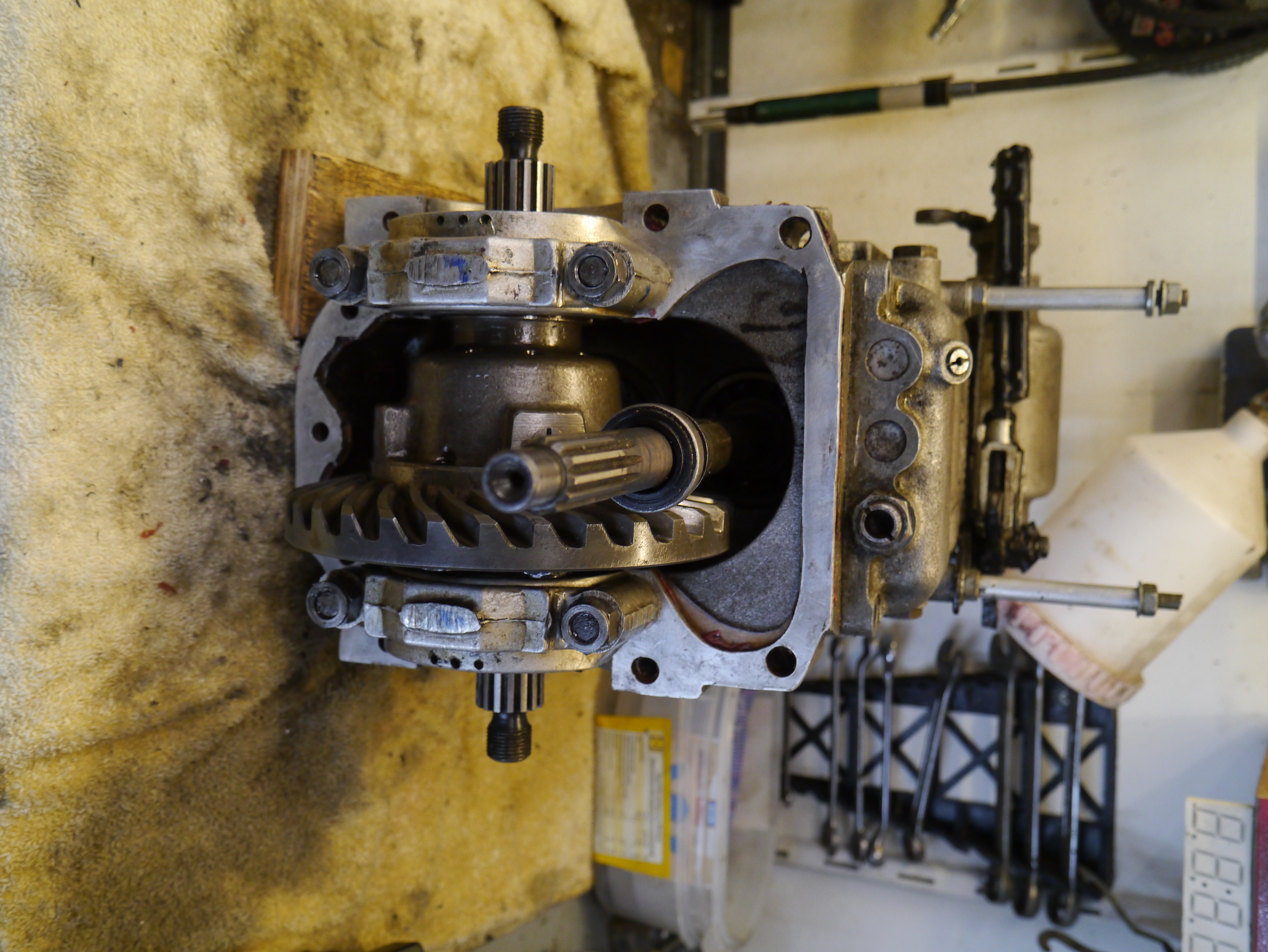
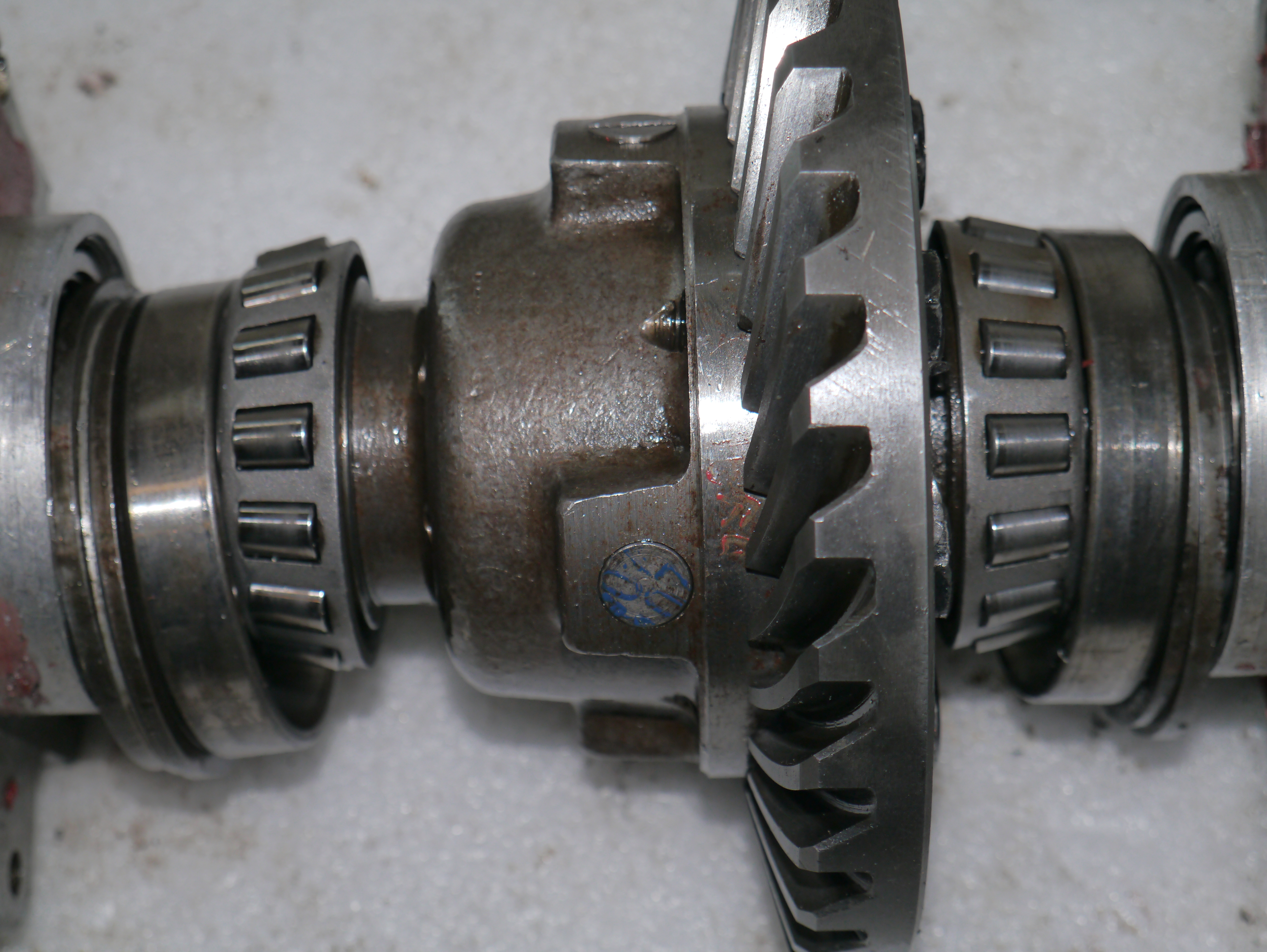
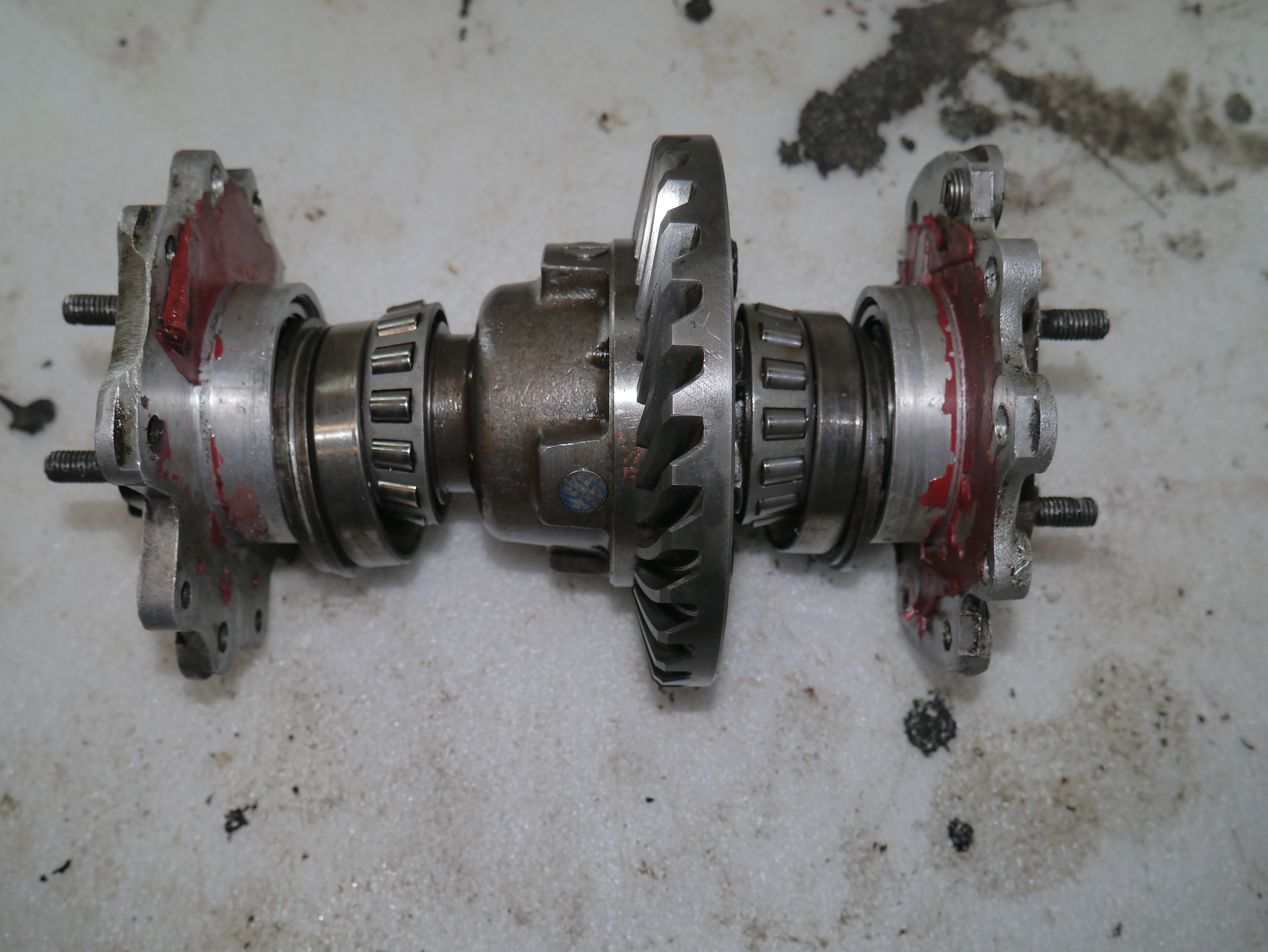
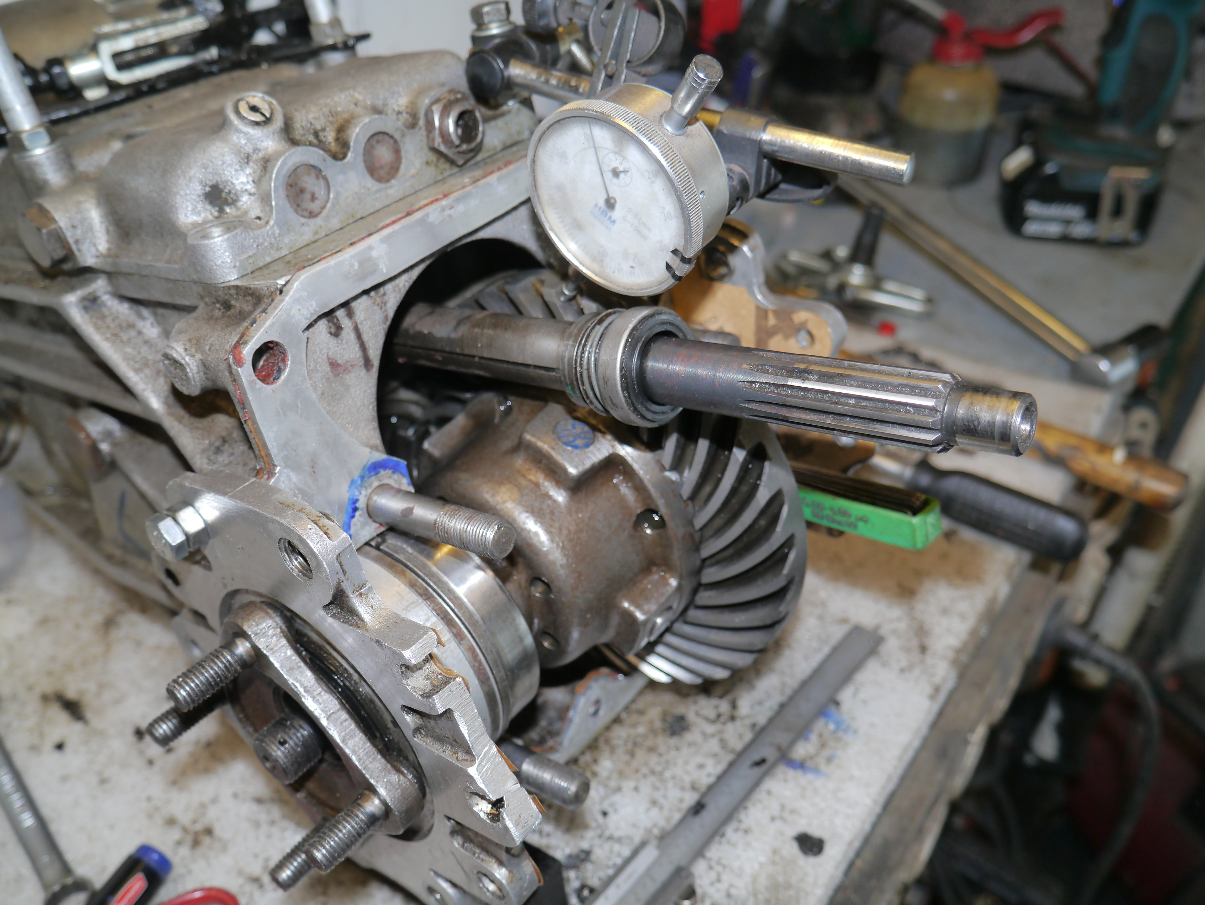
Van de weer gedeeltelijk gemonteerde onderdelen heb ik de volgende dag wel bovenstaande foto’s gemaakt . Ook van de draaibank en de vulbus in de 4-klauw…
Heel grappig, dat ik nog wel wist waarom de bouten van het differentieel allemaal verschillend zijn. Je hebt nl 4 gewone korte bouwen, 3 lange bouten met een soort van afgedraaide lange bolle punt en één afgevlakte bout met een speciaal merkteken. De 3 lange bouten borgen nl. de assen van de planetaire-en satellietwielen. 2 stuks voor de korte assen en 1 voor de doorlopende as. ja kan het zien aan de streepjes aan het eind van de asjes. De doorlopende as wordt aan de andere kant niet vastgezet en de bout die hier in gaat met het speciale merkteken trekt dus alleen de beide helften van het differentieel aan, zoal;s alle 8 bouten overigens doen. Ook de 4 korte bouten.
Nu het differentieel weer in elkaar zit nog even de bouten borgen met de zijkant van de stalen borgplaatjes, door deze omhoog te slaan tegen een vlak deel van de boutkop.
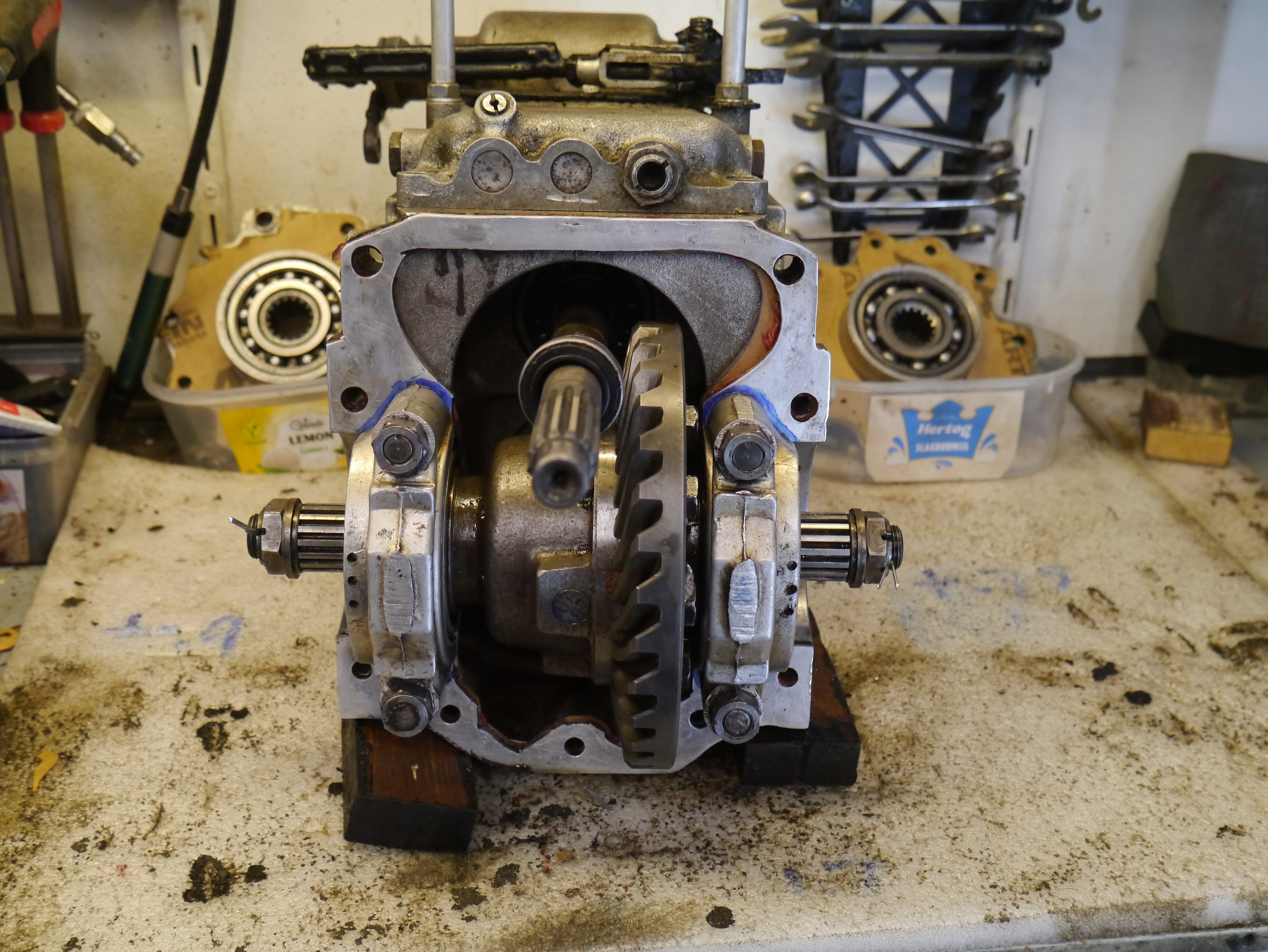
Het differentieel heb ik daarna weer in de bak geplaatst. De legers zijn aan het differentieel gebleven. Dus het differentieel in de bak plaatsen, lagerschalen erop, pasringen (wel de juiste set aan de juiste kant natuurlijk) ertegen en de lagerkappen en moeren erop. Alles los-vast monteren en aanduwen vanaf beide zijden. Gewoon met de hand.
DAG 3 – montage
Vanwege de combinatie van de ID 4-bak met het TA koppelingshuis heb ik een paar zaken die lastiger zijn van elke andere combinatie die origineel is.
Bij een TA koppelingshuis en TA 3-bak is het heel erg simpel, alleen moet je het differentieel zelf heel goed afstellen met de grote schroefringen zodat de timken lagers op de juiste plek en spanning komen waardoor de speling tussen pignon en kroonwiel op norm is.
Bij een ID koppelingshuis en ID 4-bak is het nog gemakkelijker, omdat alles in de fabriek is ingesteld en de pasringen tussen flanges en timken lagers vanuit de fabriek zijn gemonteerd. Uit elkaar en weer in elkaar gaat zonder opnieuw inmeten, mits je de juiste dikte originele pakkingen gebruikt en hetzelfde differentieel/lagers/pasringen monteert.
Omdat ik bij mijn ombouw per se GEEN ID koppelingshuis wilde gebruiken want dit past n.m.m. helemaal niet bij de TA, heb ik een oplossing gebouwd die wat minder eenvoudig is om lekdicht te monteren,.
Eventuele aanvulling(en) op dat artikel zal ik hier opnemen!
De oorzaak van het probleem:
Vervelend om te moeten constateren, maar de realiteit is dat dit probleem echt door eigen schuld komt. Ik heb me onvoldoende gerealiseerd dat de pasbus in het differentieel niet is berekend op volle belasting met 60-70 km/uur en daardoor is de pasbus ‘vastgelast’ aan de binnenkant van de interne aandrijfas (passagierszijde). Mijn opzet om het linkerwiel (bestuurderszijde) op te krikken en daardoor de sensor te testen van de cruise control ging eerst nog even goed, maar opeens liep dat vast. Gelukkig geen ongelukken gebeurd in de garage, dat was ook nog mogelijk geweest. Ik had mijn voet op de koppeling en alles stond gelijk stil. Wel even schrikken natuurlijk.
De bedoeling van het differentieel is normaal gesproken alleen om zo weinig mogelijk verschil te hebben in de hoeveelheid omwentelingen van beide wielen. Rechtuit rijden gaat sowieso goed en bij bochten zit er iets verschil in dus normaal komen er geen grote wrijvingsverschillen tussen de ujitgaande assen en het differentieel. Met de huidige reparatie door de pasbus aan de buitenkant af te draaien is het wel weer opgelost, maar het blijft oppassen om niet nog een keer zo’n actie om 1 wiel te laten spinnen uit te voeren. De ruimte tussen het differentieel en de uitgaande as (en pasbus) heb ik qua tolerantie wel iets ruimer gemaakt dan de ruimte die ik bij de originele bouw aan de binnenkant van de pasbus heb aangehouden. De olie vloeit er in ieder geval goed doorheen, ook in koude toestand. Dat zou i.i.g. een meer stabiele werking moeten garanderen.
Aanvullingen m.b.t. de montage van de versnellingsbak:
In het ID-bakhuis heb ik alle M8-gaten die gebruikt worden om de beugel waarmee de bak en motor aan de eerste chassisbeugel wordt gemonteerd, voorzien van helicoils. dat zorgt voor een permanente goede fixatie. En dat is nodig, omdat ik bij de demontage merkte dat 2 van de 6 stuks M8-bouten waren losgekomen, ondanks montage met threadlocker.
De M8-gaten zijn onderdeel van de gaten rondom de flanges waarmee zowel (eerst) de flanges als (daarna) de ophangbeugel van de bak wordt gemonteerd.
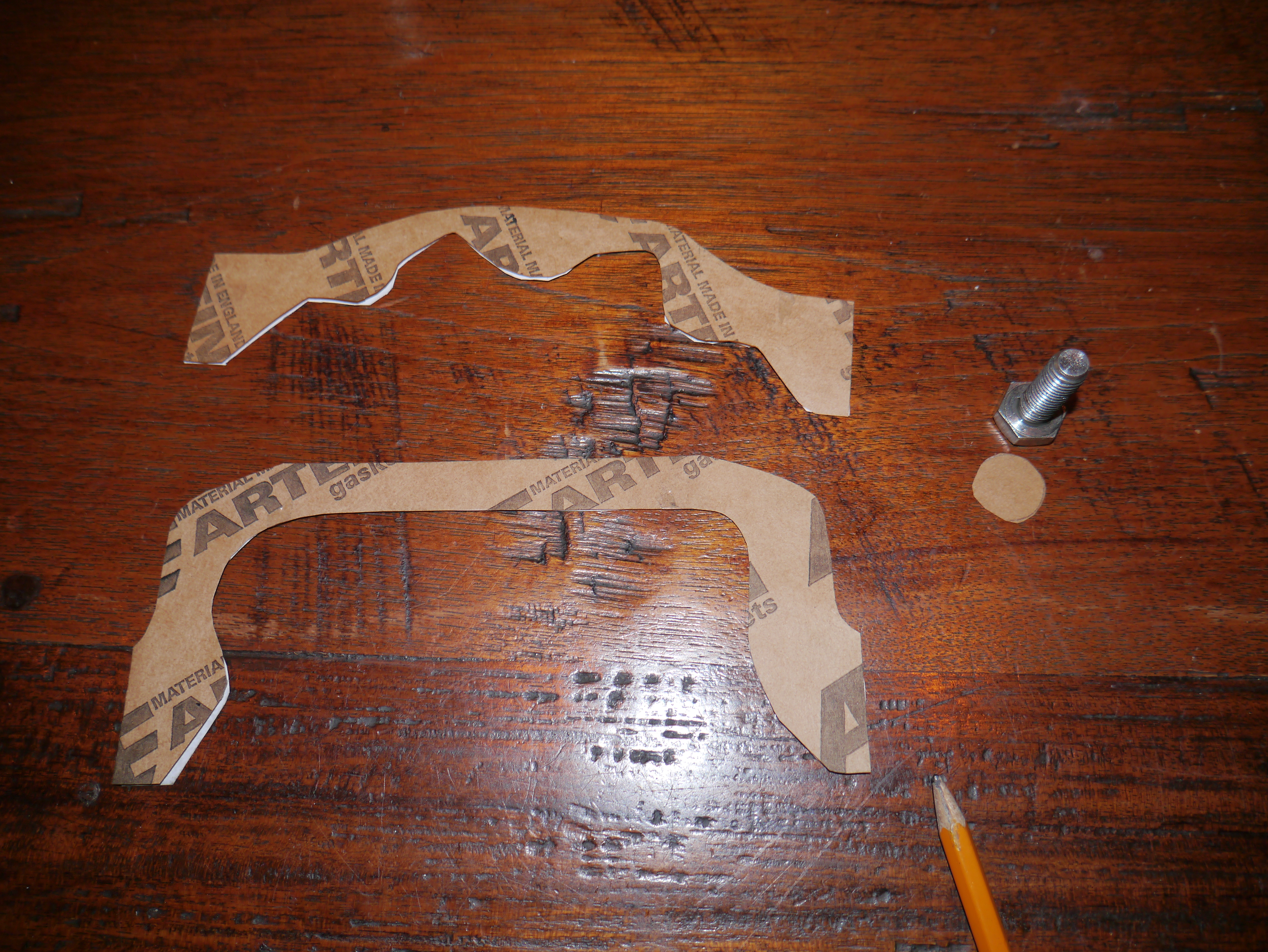
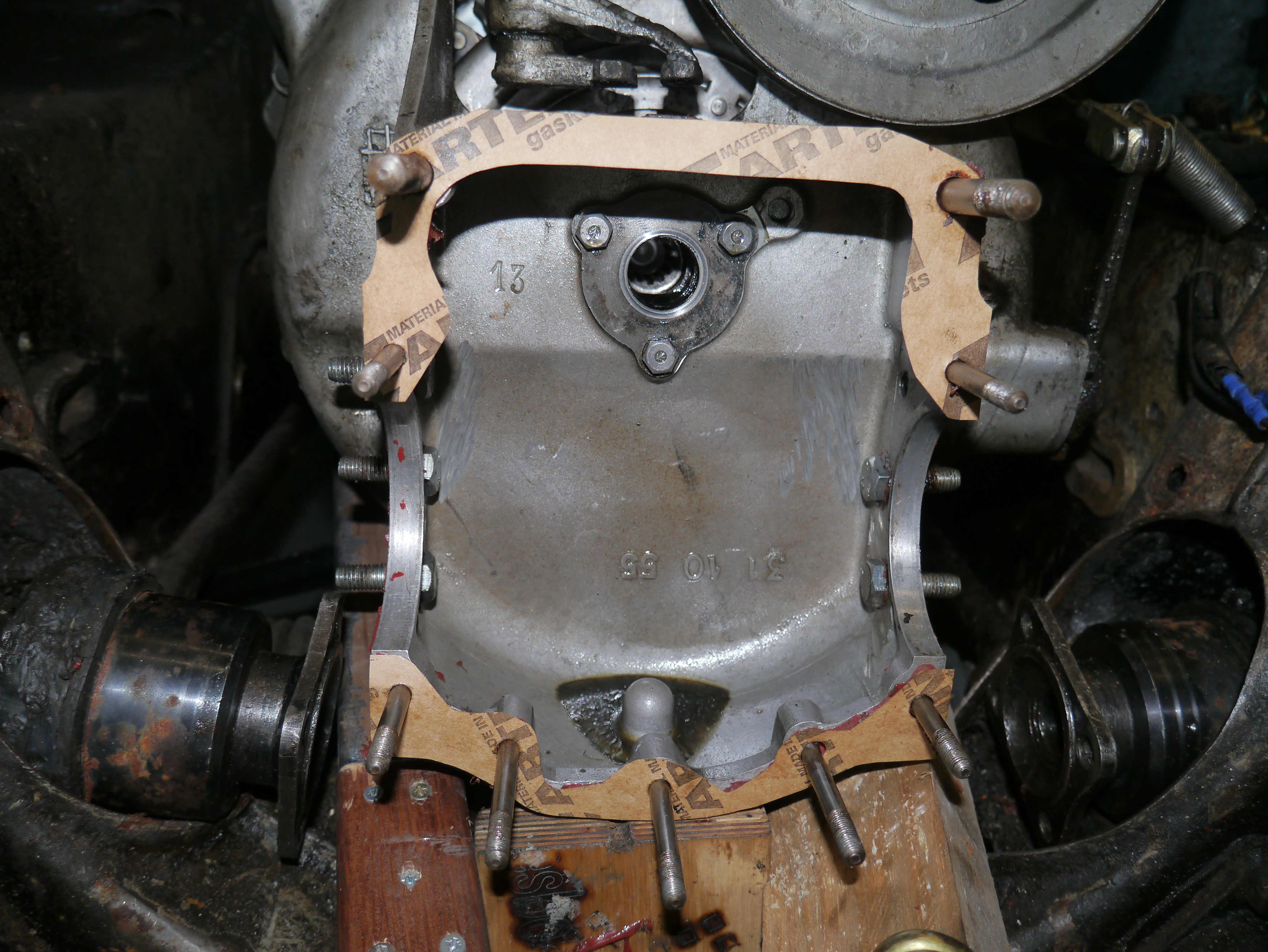
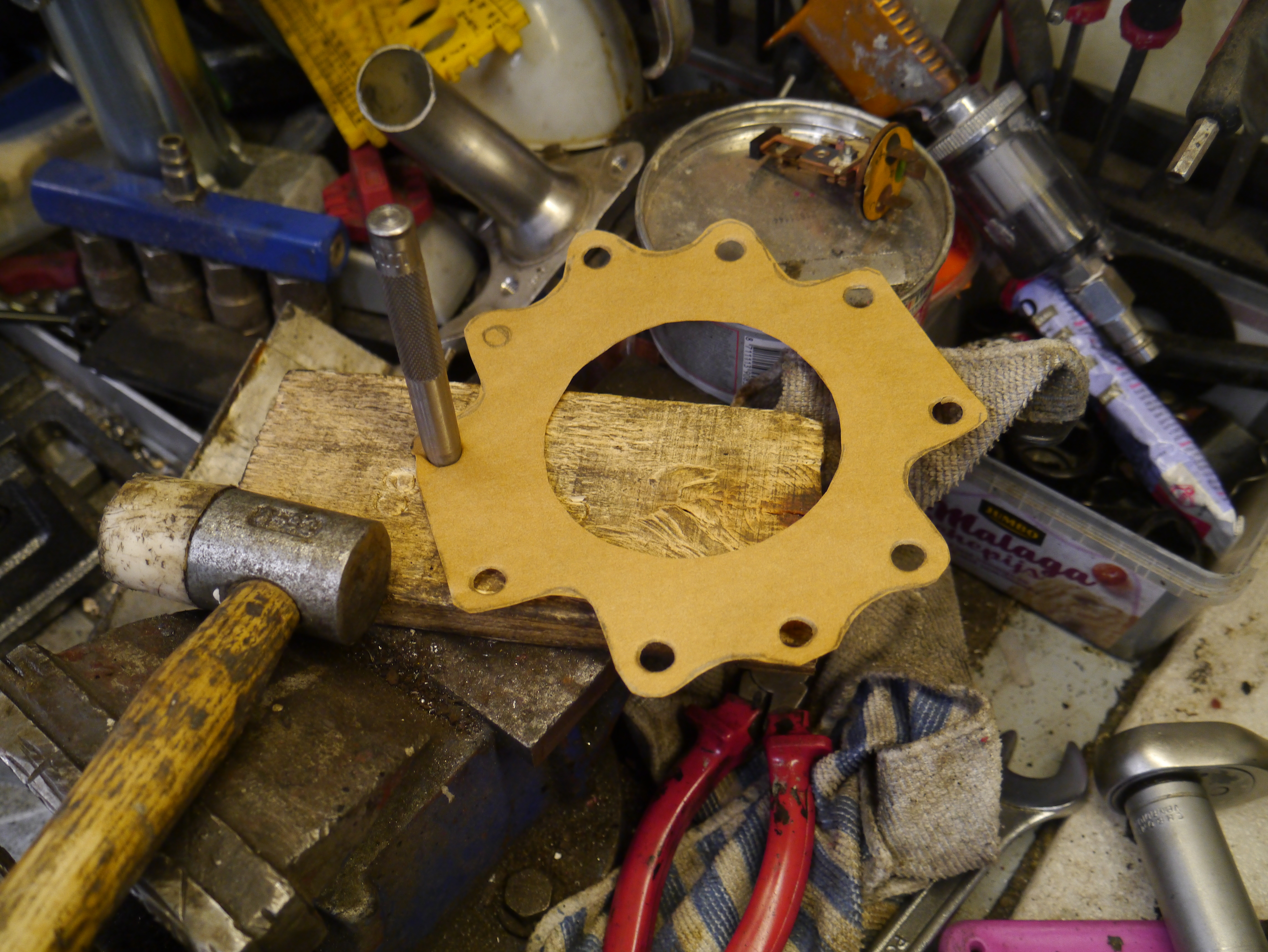
Om alles weer te monteren moet ik ook nog even nieuwe pakkingen maken…
Bij de combinatie van ID-bak en TA-koppelingshuis is de volgorde van montage heel belangrijk. Eerst moet het differentieel worden uitgepast in de bak zodat de timken lagers op de juiste plek worden gefixeerd. Hiermee wordt de passing van het kroonwiel op het pignonwiel geregeld.
Dat komt omdat er TA-lagerkappen op de ID-bak worden gemonteerd over de Timken klagers en -ringen heen. . Bij gebruik van het originele ID- koppelingshuis worden de Timken lagers vastgezet vanuit de binnenkant van het koppelingshuis dus kun je dat later doen nadat de flanges zijn gemonteerd en daardoor de timken lagers hebben gefixeerd op de vooraf ingestelde plek.
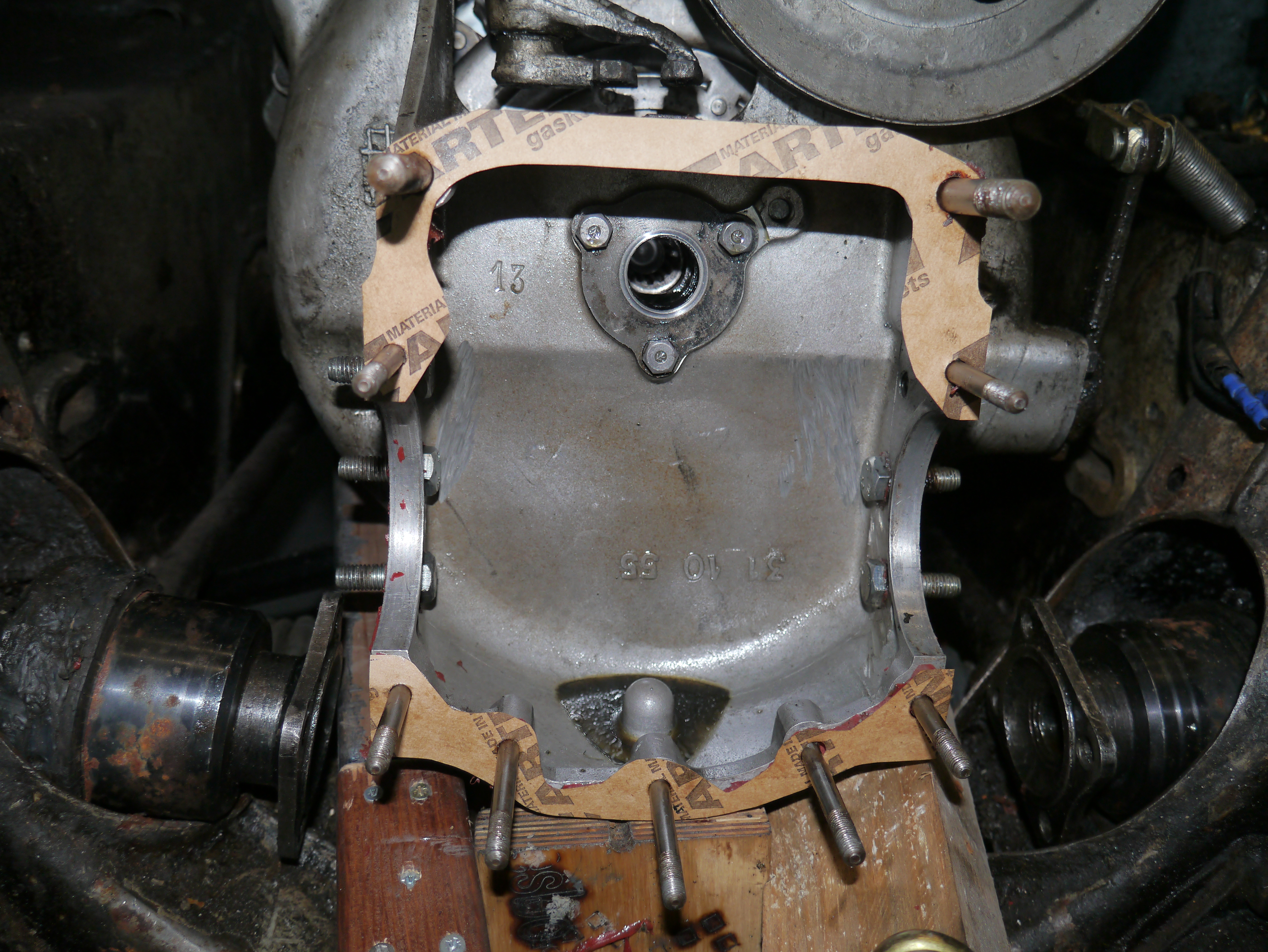
Het passen van de flanges moet op de werkbank dus de lagerkappen erop, losjes vast. Dan de flanges erop aan beide kanten en ten minste de 6 M8 bouten op de flanges erop en vast. Dan de lagerkappen definitief afspannen met de lagerkapmoeren, uiteraard gelocked met 271 high torque threadlocker. Ik heb vorige keer alles helemaal uitgepast en gebruik voor de flanges GEEN pakkingen,, alleen siliconen pakking. Dat is de laatste jaren heel goed blijven zitten, lekvrij.
Maar- alles moet helemaal schoon en echt vetvrij zijn!
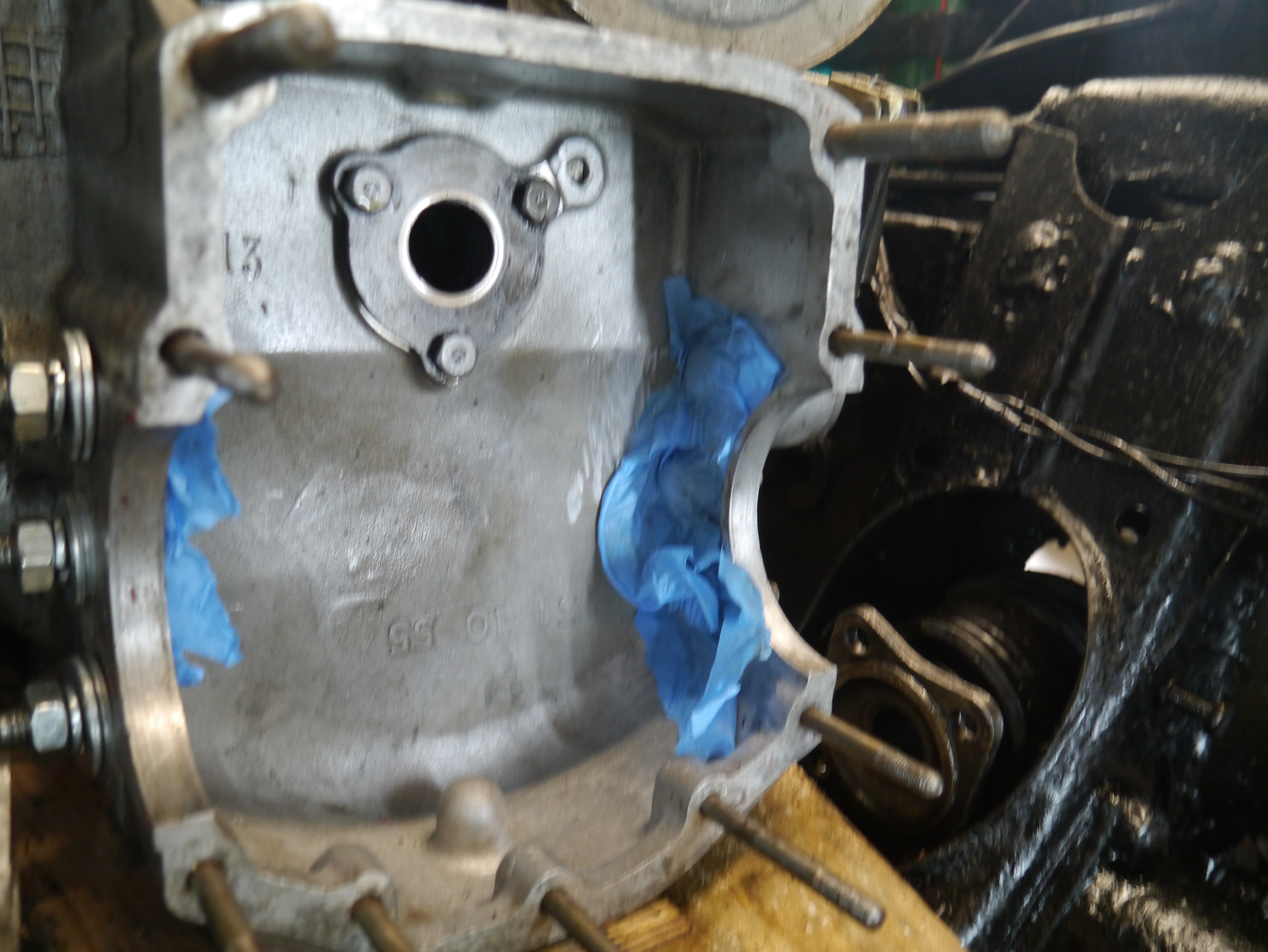
Het koppelingshuis wordt voorbewerkt. De M8 bouten die naar buiten steken zijn eerder al gemonteerd met loctite 271, en de montage is destijds gedaan inclusief een papieren pakking. Dat heeft nooit gelekt maar 1 bout is los gekomen bij de demontage. Dat was de Linker (bestuurderszijde) hoogste bout, waarmee ook de ophangbeugel vast zit. Deze bout is vervangen en opnieuw gemonteerd. Om er voor te zorgen dat alles nog beter is gefixeerd worden de 6 bouten die in het koppelingshuis zitten vervangen door nieuwe exemplaren en worden deze gemonteerd met Loctite EA3455 2K epoxy aluminium-gevulde lijm. De 6 bouten worden daarna met ringen en moeren vanaf de buitenkant van het koppelingshuis vastgezet om uit te harden.
Na het goed passen en vast zetten van het differentieel (i.c. de Timken lagers) gaan de flanges er weer af.
DAG 4:
Nu de bak losjes op het koppelingshuis monteren met pakkingen die met Vloeibare Pakking dunnetjes 2-zijdig zijn bedekt. deze 2 pakkingen worden voorgemonteerd op het koppelingshuis.
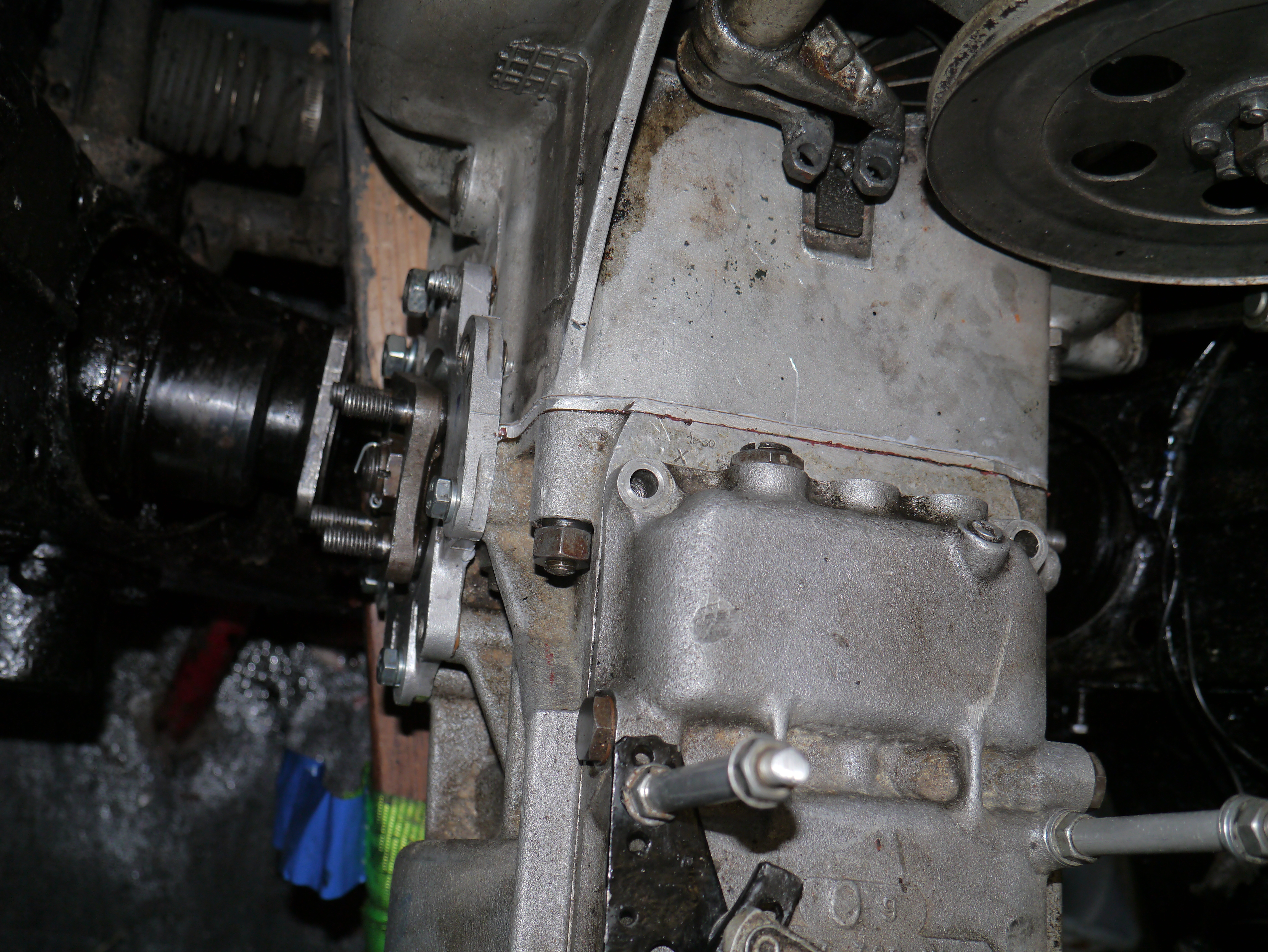
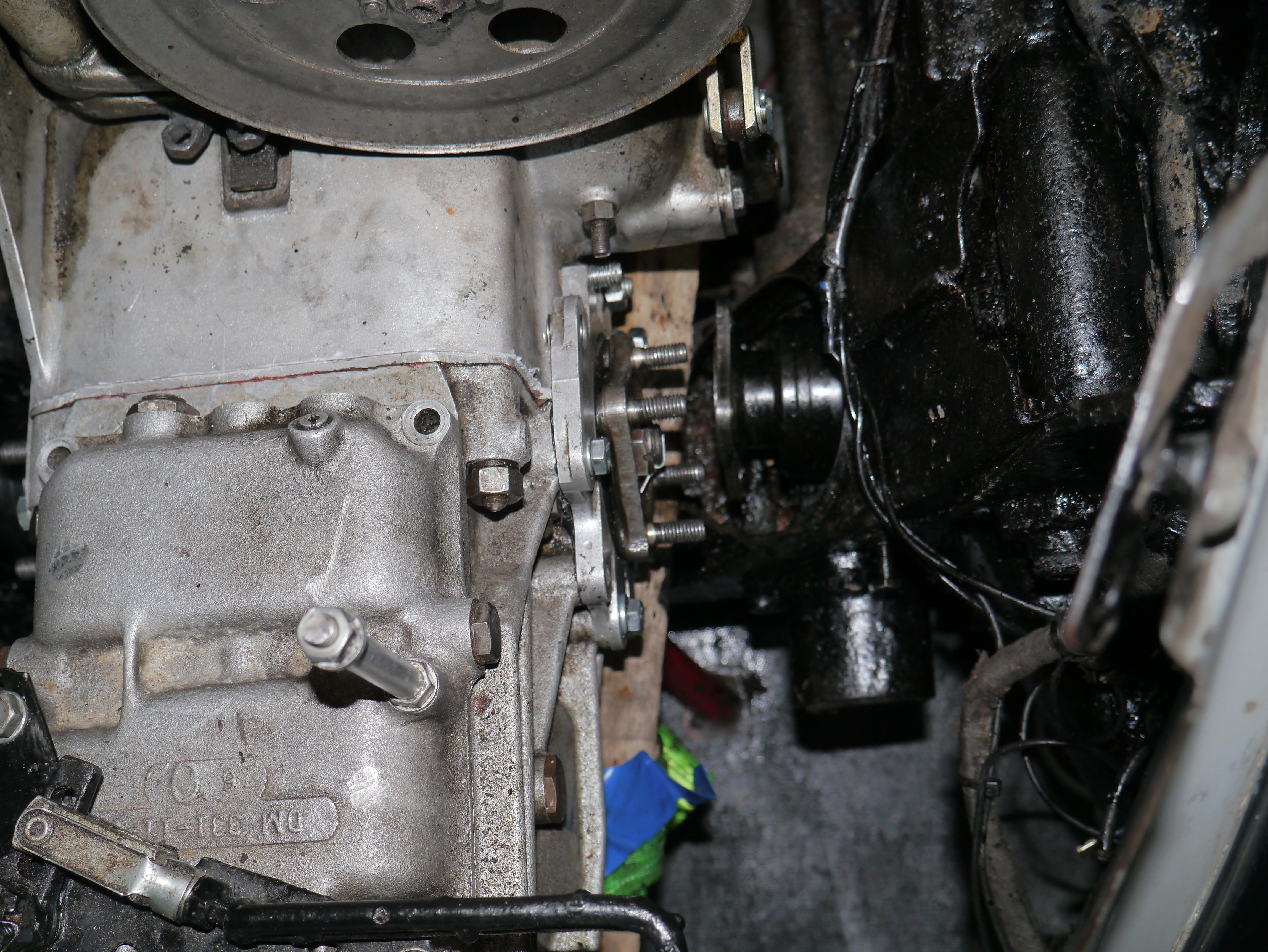
Na plaatsen van de bak komen de bedieningsstangen, de ophangbeugel en de flanges erop met op het pasdeel van de flanges aan de kant van het koppelingshuis hi-temp silicone. De silicone komt met een dubbele laag aan de zijde van het koppelingshuis. De pakking van de flanges heb ik aan de bakzijde aan beide kanten van de pakking van VP voorzien en de hele voet van de flange, waar deze in de uitsparing van bak en koppelingshuis komt, een kruiplaagje hight-temp silicone in de hoek.
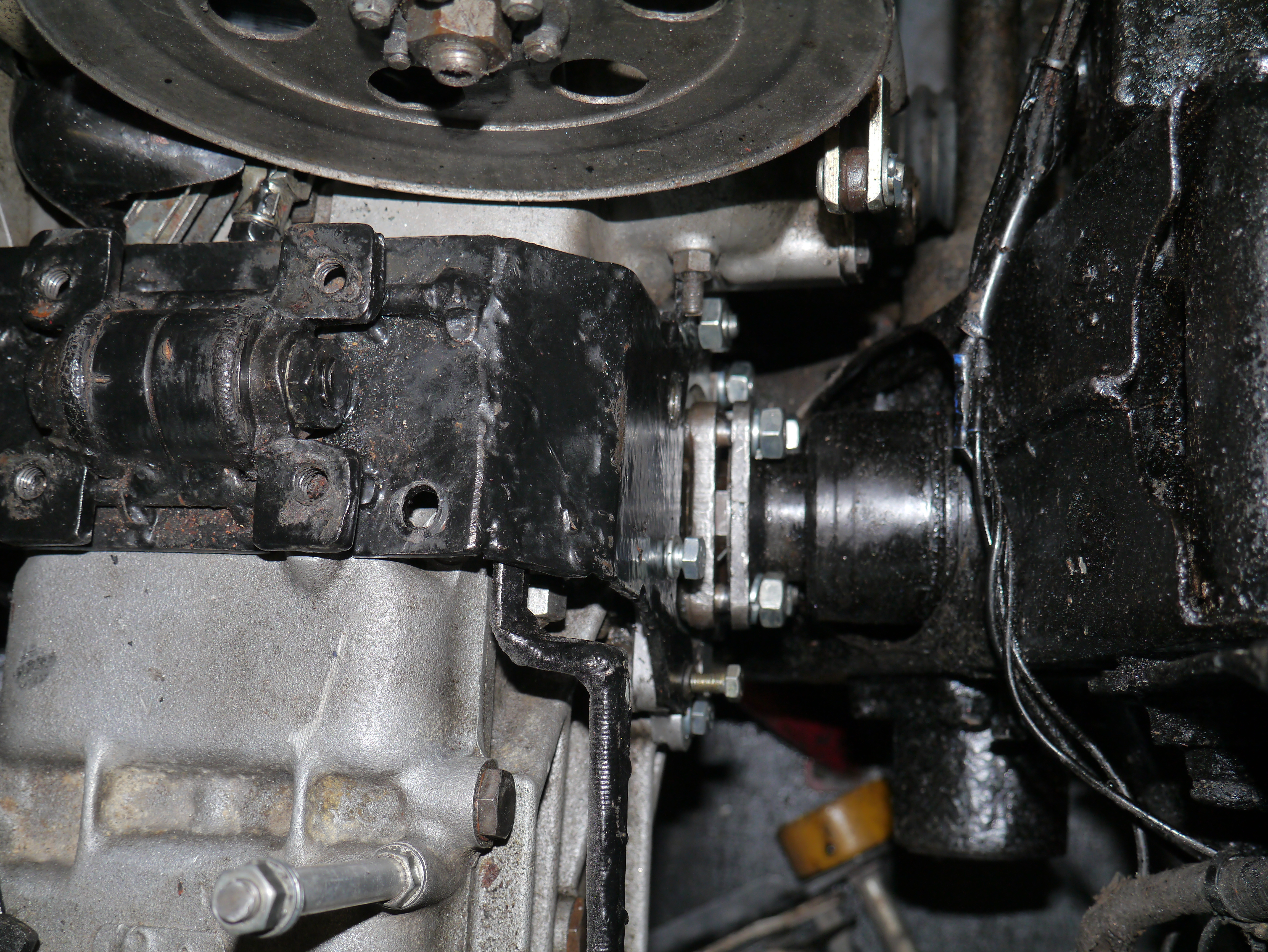
Om de flanges goed te monteren moeten de 2 grote ringen en moeren van de bevestiging van beide bakasjes er voor zorgen dat de asjes helemaal over de spiebanen van de halve aandrijfassen schuiven. Dit moet eerst worden gedaan, pas daarna kunnen de flanges worden vastgezet met de bouten en moeren rondom. En de bak mag niet te vast zitten, anders passen de binnenkanten van de flanges niet soepel in de opening en kun je de lagers van de bakasjes ongewild uitpersen.
Hierna: de flanges losjes rondom met alle bouten en moeren monteren aan bak en koppelingshuis.
Nu stukje bij beetje alles vastdraaien, rondom de bak aan het koppelingshuis en de flanges. Maar nog niet TE vast! Mijn ervaring met siliconen is, dat je een halve dag wacht en dan pas definitief met het juiste aandraaimoment alles vast zet en borgt. Dat betekent dat het gebruik van thread locker lastig wordt.
Na mijn ervaring met de threadlocker op de bouten en moeren van de flanges en versnellingsbak heb ik besloten om in plaats van threadlocker zelfborgende ringen te gebruiken voor de bak en de flanges. Het enige dat ik weer met threadlocker heb gemonteerd zijn de moeren van de lagerkappen van het differentieel.
Het was even zoeken naar M7 veerringen maar bij een scooterzaak toch de juiste versie en sterkte gevonden!
Na een halve dag wachten definitief aandraaien van de moeren en bouten. Dit moet ook in een voorgeschreven volgorde: Eerst de flange schroeven van de bakzijde, dan de bak aan het koppelingshuis, daarna als laatste de 6 grote moeren van de flanges aan het koppelingshuis. Deze 6 moeren heb ik niet te vast aangedraaid, gewoon net op spanning met de hand aangedraaid. Precies zo, dat de veerring net helemaal is ingeveerd. op de bovenste bouten kon geen veerring, die heb ik zonder veerring en zonder loctite gemonteerd.
Omdat ook de ophangbeugel gelijk met de bak wordt gemonteerd niet vergeten om bij het plaatsen van de ophangbeugel ook de bedieningsstangen eerst te monteren, en vooral de 2 lange schroeven die bovenin de bak worden geschroefd direct te plaatsen inclusief de vulbussen tussen de ophangbeugel en bak . De schroeven heb ik allemaal eerst losjes gemonteerd tot de bak verder helemaal goed is gemonteerd.
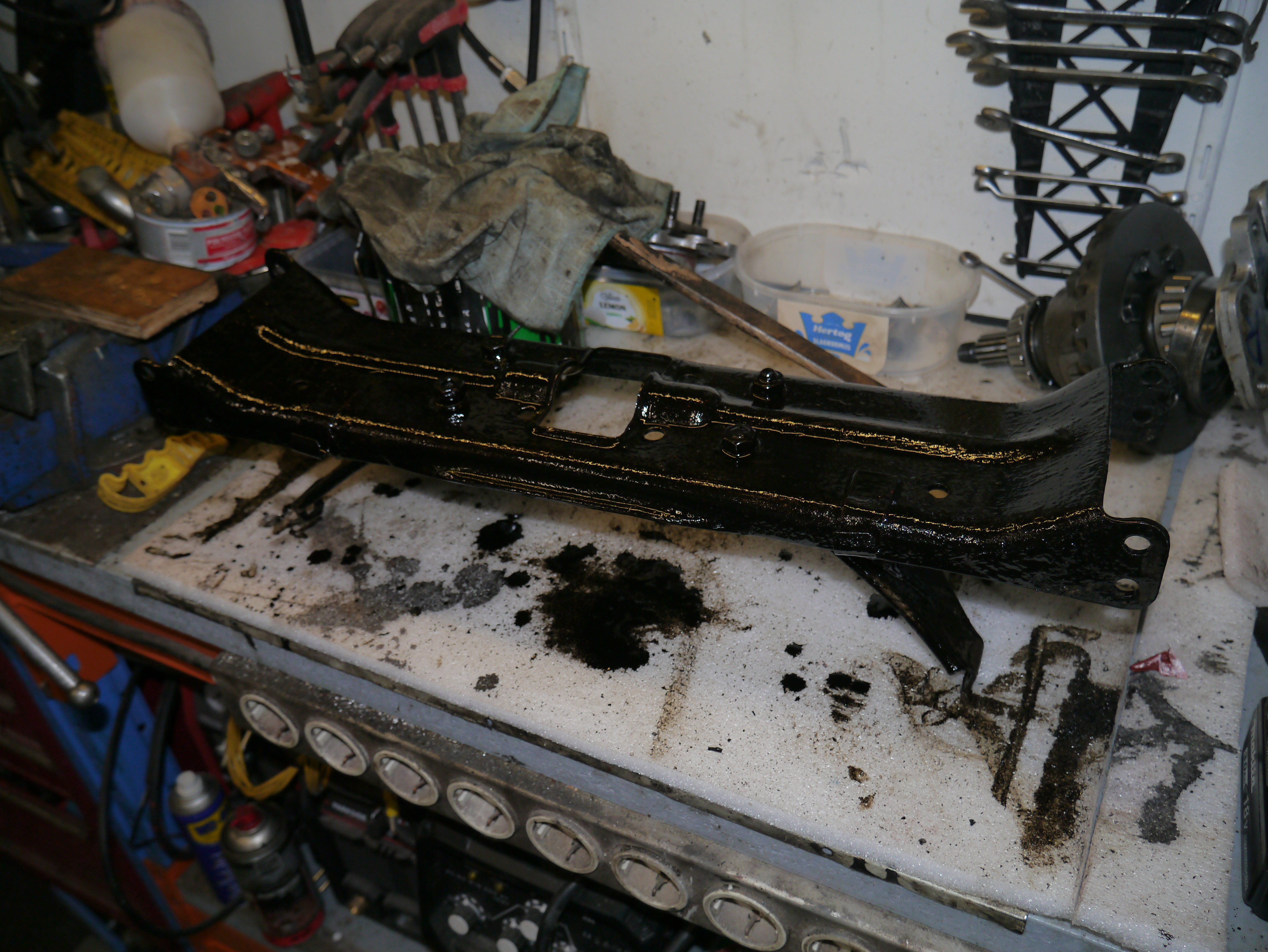
Tussendoor heb ik ook alle delen die nu bereikbaar zijn, met TEMU antiroest zwarte verf behandeld. Dus ook de binnenkanten van de wieg, de bak-, c.q. aggregaatbeugel, de aandrijfassen en alle omliggende metalen delen. De versnellingsbak en het koppelingshuis blijft aluminium zoals origineel.
Na de montage van de bak heb ik versnellingsbakolie type Classic Gear EP 90 van KROON OIL gebruikt om de bak te vullen. Het is een type olie voor oude bakken die eigenlijk GL4 nodig hebben, maar dan modern ontwikkeld. Ben benieuwd!
Nu is het een goed moment om te checken op lekkages. Een mooie methode vind ik om de bak te vullen met olie , de garagekachel erop te zetten en te kijken of er lekkage is. Beter vooraf te doen dan na volledige afmontage. Neem hier de tijd voor (minimaal een dag) en maak alles vooraf helemaal schoon en droog. En..volgende dag was alles nog helemaal droog. Pfff.
DAG 5: Het volgende gedaan:
Controle of de motor goed in beide motorsteunen rust. Dat was dus niet zo, aan de bestuurderskant was de pen uit de veer geschoten, dat kostte nog wel wat moeite om alles weer op de goede plek te krijgen.
Aandrijfassen losjes gemonteerd inclusief magneet voor CC op linker aandrijfas
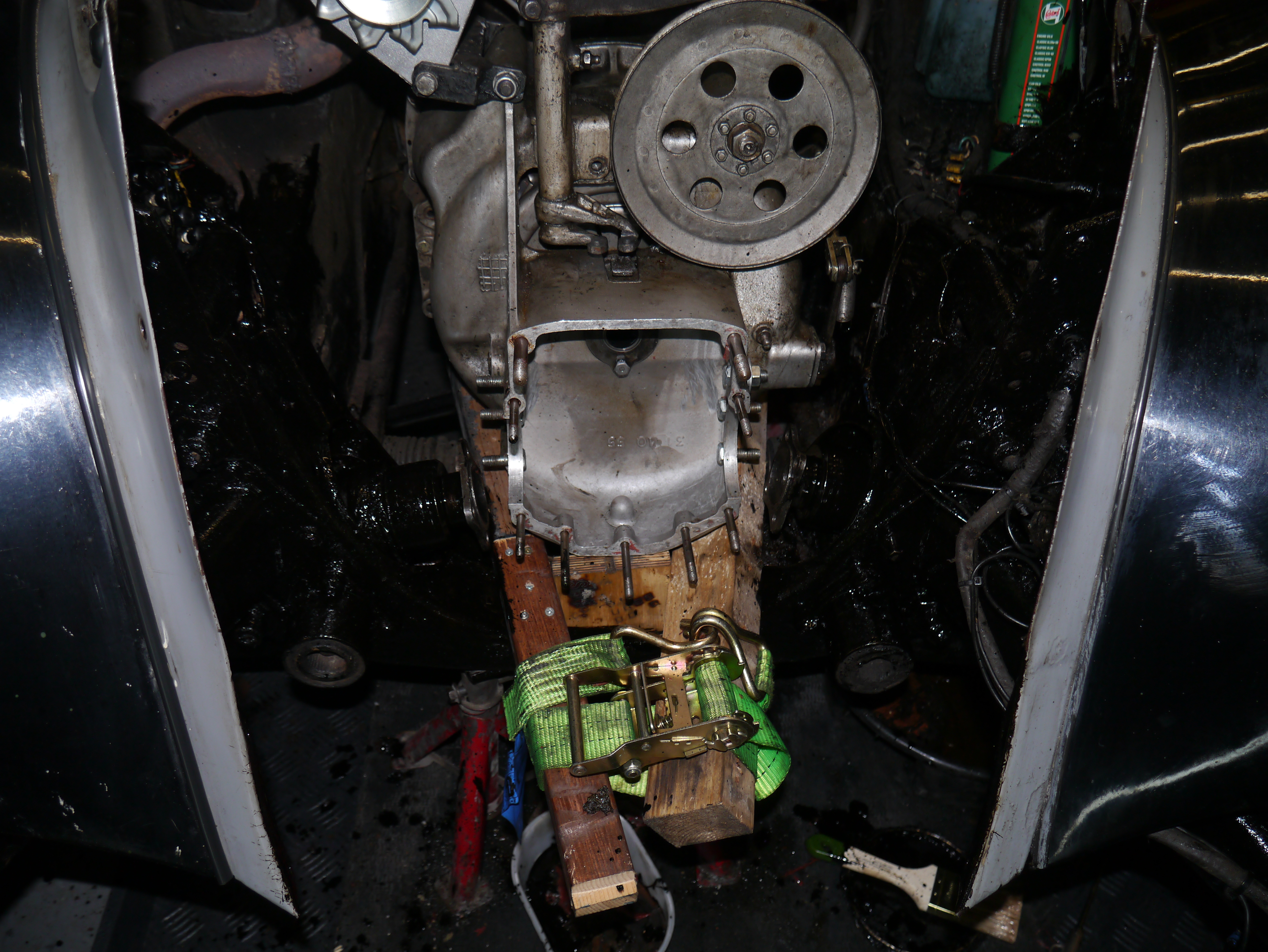
Blokje hout onder versnellingsbak in wieg (voorzorg) gehouden en laten zakken op blokje hout
Linker voorwiel: Bovenste fusee weer monteren. Ik heb alle vet verwijderd en vervangen, en ik heb een dop afgedraaid om de binnenmoer van de bovenste fusee goed te kunnen bereiken. Het helpt wel dat ik overal origineel gereedschap voor heb, zoals de bovenste fusee-sleutelset.
Remleiding weer gemonteerd
Remmen ontlucht en vloeistof aangevuld DOT3. Er kwam hele donkere drab uit de linker voorrem, even lekker doorgeperst tot alles er uit was.
Traverse subframe gemonteerd en de bakbeugel gemonteerd aan traverse
V-riem dynamo/waterpomp gemonteerd
Dynamo gesteld en kachelslangen-beugel gemonteerd
schutplaatje versnellingsstangen/toren gemonteerd
waterpompventilator vergeten te monteren
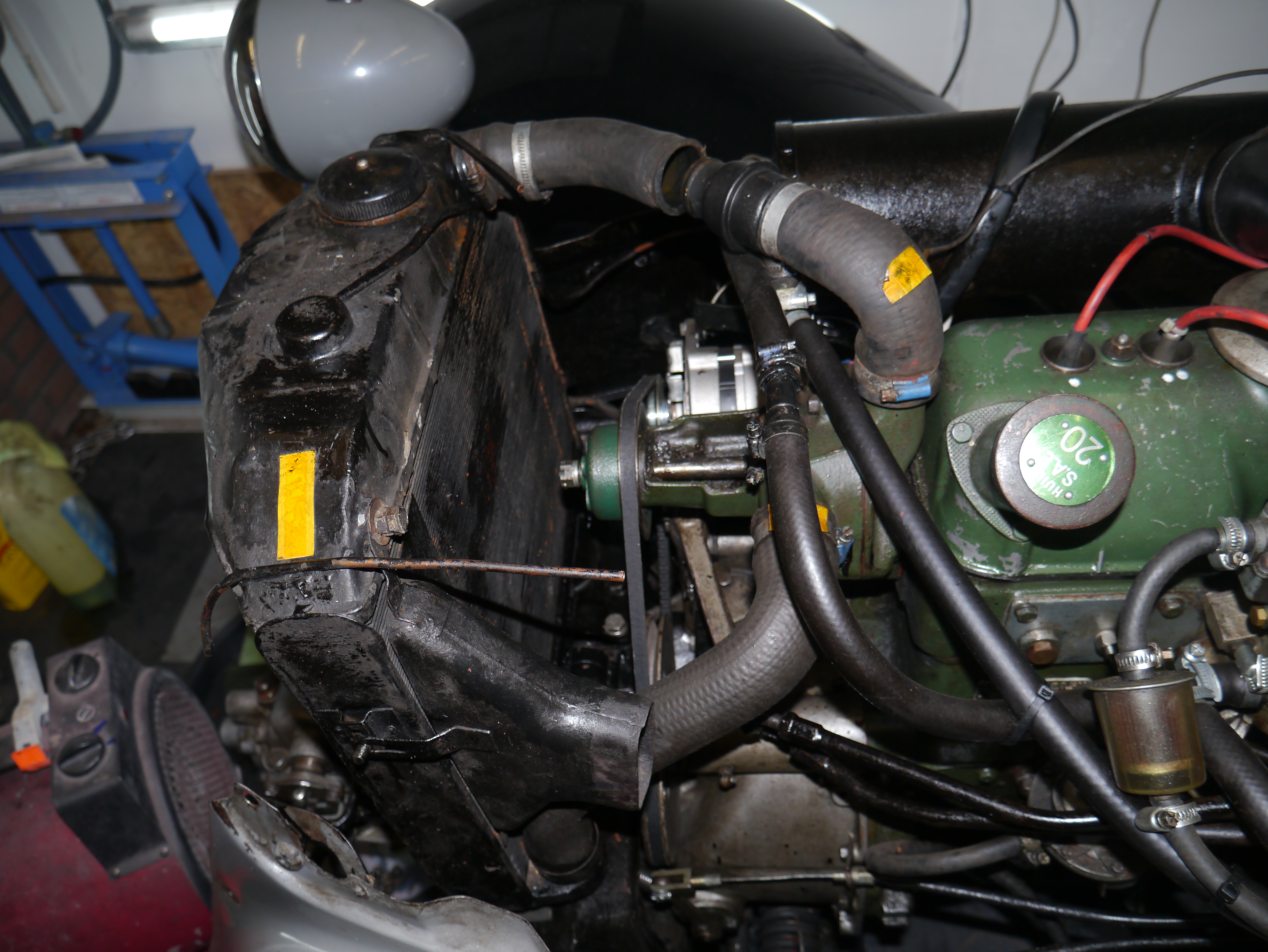
Schroefdraad montage radiator 2xM10 opgezuiverd en radiator gemonteerd met nieuwe M10 ringen en moeren, in kopervet
Koelvloeistof gevuld
DAG 6: Het volgende gedaan:
Assteunen onder de voorwielophanging L en R zodat alles kan worden getest. Steunen zo ver als mogelijk bij de wielen geplaatst om een normale situatie te simuleren. Kachel op de versnellingsbak gezet en voorverwarmd tot ca 40 graden Celsius. Schakelen, koppelen, alle versnellingen getest en ca 70 km/uur laten draaien met beide wielen vrij in de lucht. Alles in orde dus verder naar het afmonteren!
Radiator afgetapt, gedemonteerd, koelvin gemonteerd, radiator gemonteerd en met koelvloeistof afgevuld
Toeters gemonteerd
Radiatorhoes bediening gemonteerd
Meetkabel versnellingsbak gemonteerd
Opnemer cruise control L voorwiel bij bakas gemonteerd
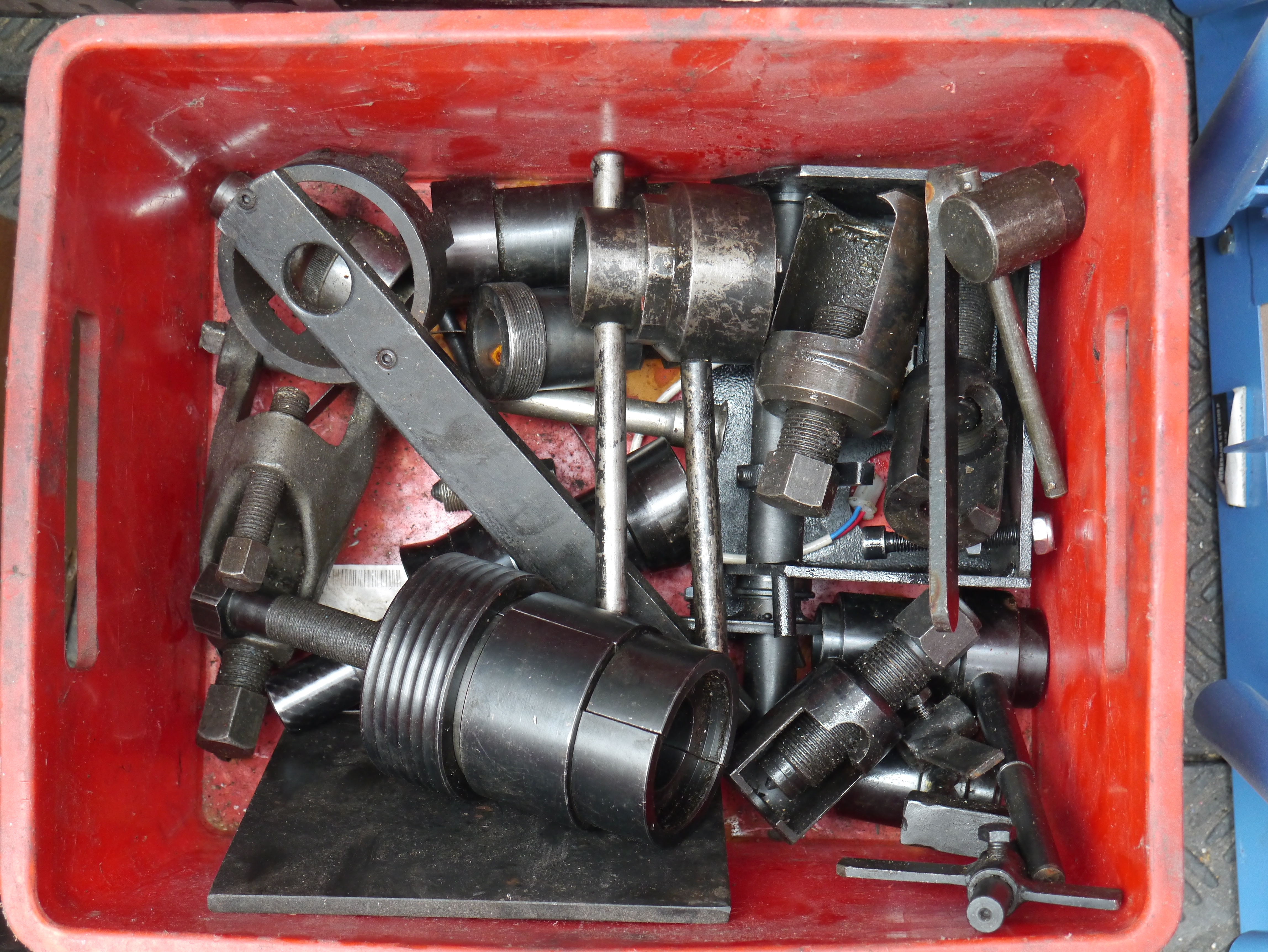
Het Traction ‘speciaal’ gereedschapDe grill aan de binnenkant met roestbeschermer behandeld
DAG 7: Het volgende gedaan:
Kabelboom gemonteerd incl. connectorblokje op coque passagierszijde (voor koplamplicht R)
Grille gemonteerd
Kachelbuis gemonteerd
Voorbumper gemonteerd
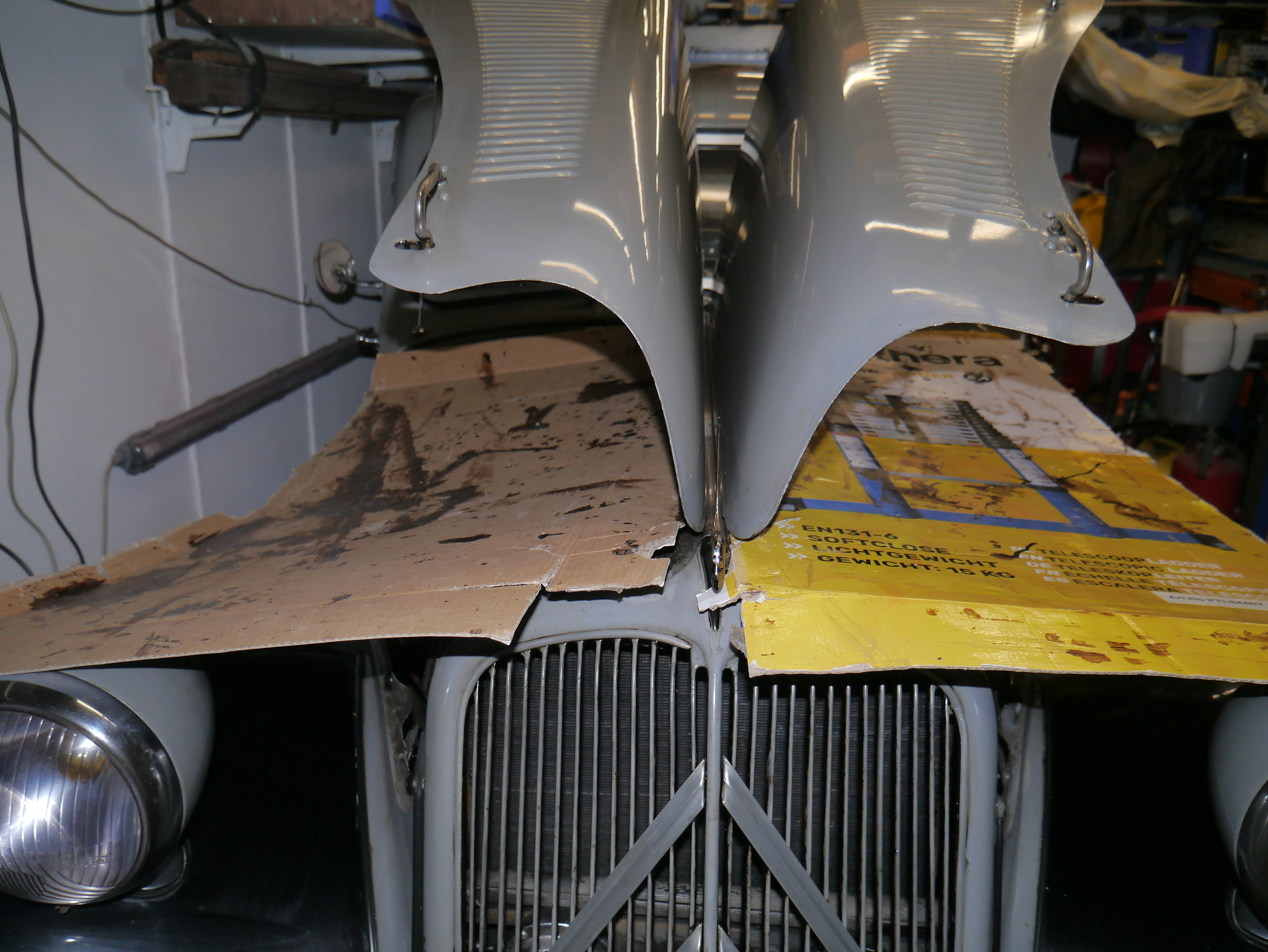
Motorkap gemonteerd
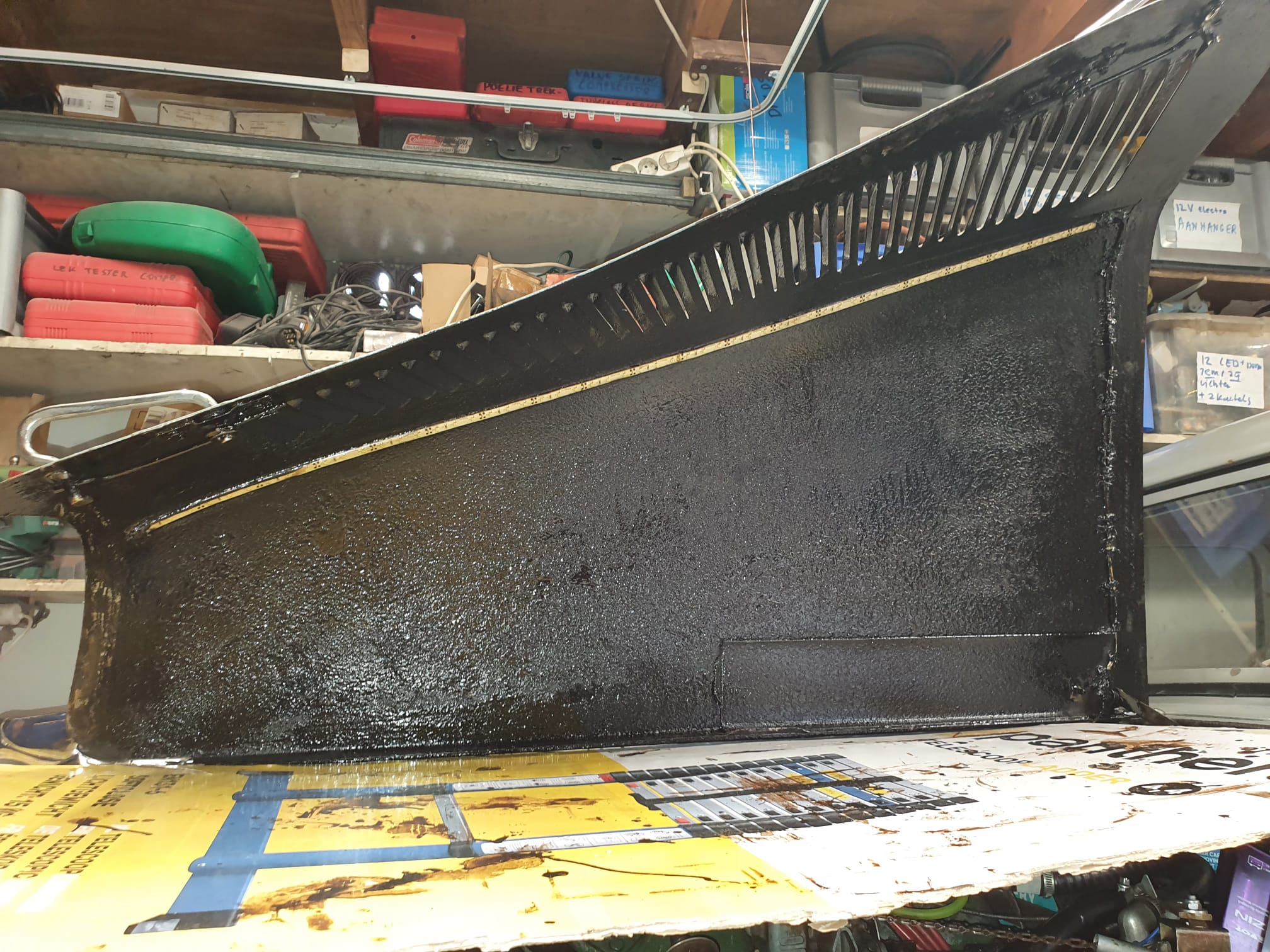
Binnenkant van de motorkappen behandeld, nu nog even uit laten druipen….
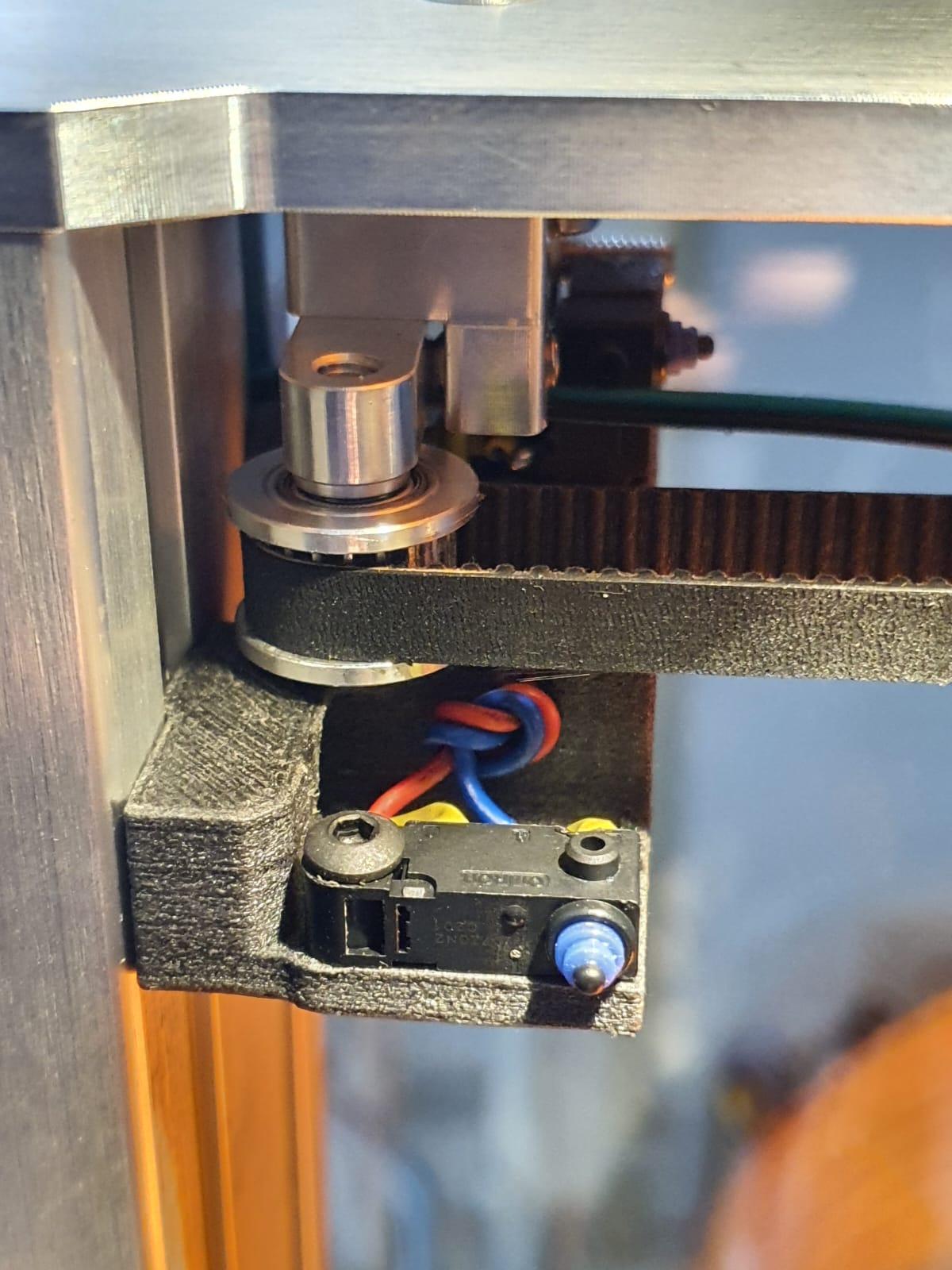
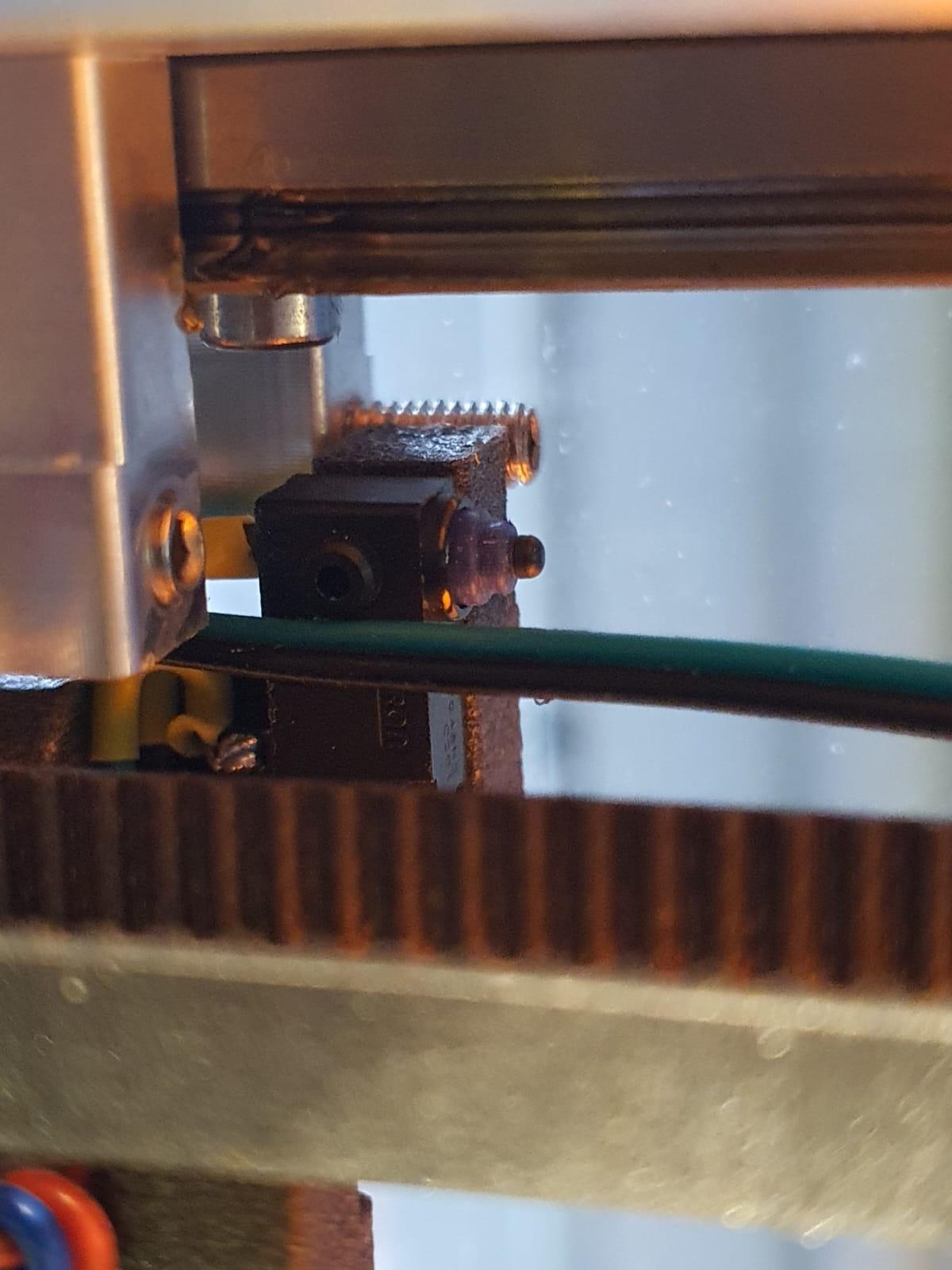
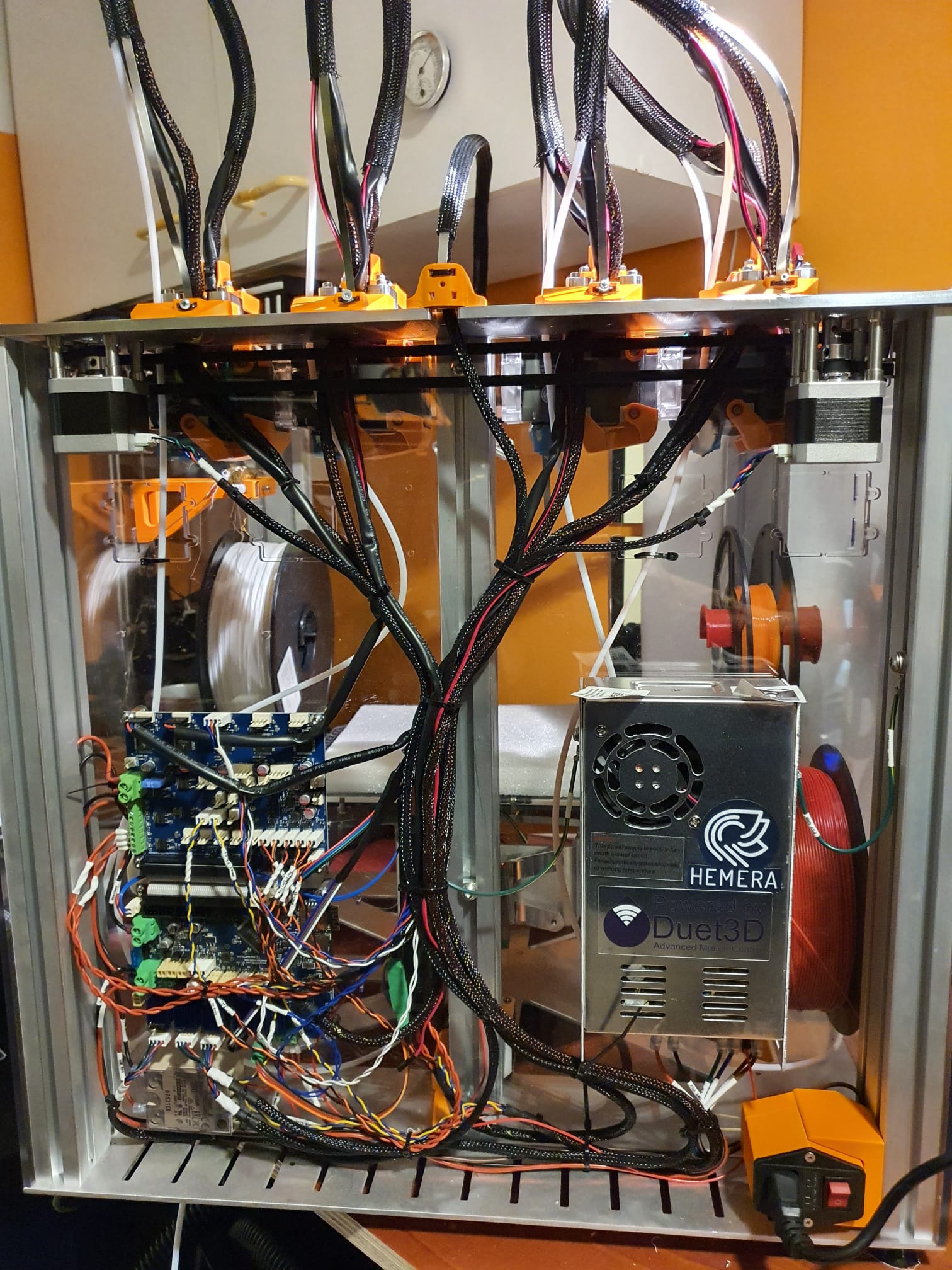
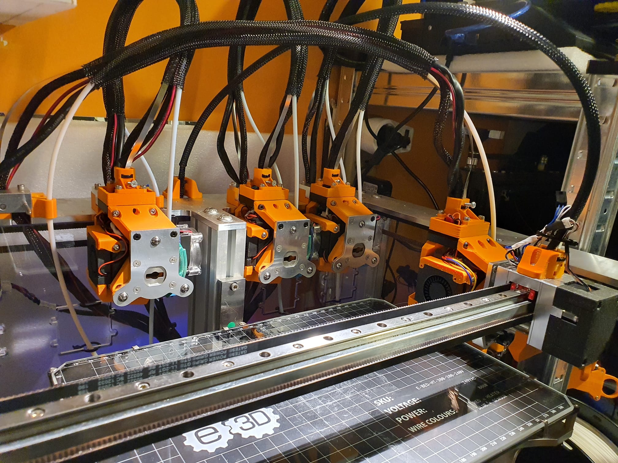
Nadat ik de homing schakelaars voor X en Y op de E3D toolchanger had geïnstalleerd, had ik eindelijk een fatsoenlijk startpunt om de pickup en parking van het gereedschap af te stellen.
Oorspronkelijk gebruikte ik sensorloze homing, maar dit veroorzaakte wisselende offset-waarden van de X- en Y-posities van de machine. Het gereedschap kon dus niet consequent worden opgepakt of thuisgebracht na een reset.
Nu werkt alles prima en veranderen de X-Y waarden niet meer na een reset.
Wat ik dis was om eerst wat macro’s te maken voor een eenmalige instelling van de X en Y positie van de 4 gereedschappen voor de positionering van de gereedschapskop. Als je dit niet doet, moet je elke keer dat je de waarde van X wilt veranderen, alle X waarden handmatig veranderen in 8 macro’s.
Dit is gedaan met een aantal globale variabelen. Nadat deze in een macro zijn gedefinieerd, moeten ze worden aangeroepen voordat ze worden gebruikt. In Config.g heb ik een verwijzing gemaakt om de macro van de globals.g macro aan te roepen, zodat deze telkens wordt uitgevoerd als je de Duet opstart.
In config.g heb ik na de Tool definities de M98 code toegevoegd om de globale definitie van de gebruikte variabelen te starten:
M98 P”0:/sys/globals.g” ; Maak globale variabelen aan in deze globals.g macro
Dit macrobestand ziet er in mijn geval als volgt uit en wees u ervan bewust dat de werkelijke variabelen per machine zullen verschillen, maar dit kan u een uitgangspunt geven:
global T0_X_dock=-12.3 ; X-Parkeerpositie van gereedschap 0
global T0_Y_dock=225.2 ; Y-Parkeerpositie van gereedschap 0
global T1_X_dock=80 ; X-Parkeerpositie van gereedschap 1
global T1_Y_dock=225.9 ; Y-Parkeerpositie van gereedschap 1
global T2_X_dock=212 ; X-Parkeerpositie van gereedschap 2
global T2_Y_dock=226 ; Y-Parkeerpositie van gereedschap 2
global T3_X_dock=304.7 ; X-Parkeerpositie van gereedschap 3
global T3_Y_dock=225,4 ; Y-Parkeerpositie van gereedschap 3
De bestanden tfree 1-3 en tpre 1-3 zien er dan zo uit voor T0, en je kunt de anderen maken door gewoon T1 , T2 of T3 in te vullen waar nu T0 staat:
;tpre0.g
;opgeroepen voordat gereedschap 0 is geselecteerd
;Koppeling ontgrendelen
M98 P”Coupler – Unlock.g”
;Verplaatsen naar locatie
G1 X{global.T0_X_dock} Y200 F50000 ; was X-10.5
;Naar binnen
G1 X{global.T0_X_dock} Y220 F50000
;Verzamelen
G1 X{global.T0_X_dock} Y229.2 F1000 ;was f2500
G1 Y{global.T0_Y_dock} F1000
;Koppeling sluiten
M98 P”Coupler – Lock.g”
WAARSCHUWING! WAARSCHUWING! WAARSCHUWING! WAARSCHUWING! WAARSCHUWING! WAARSCHUWING! WAARSCHUWING! WAARSCHUWING! WAARSCHUWING! WAARSCHUWING! WAARSCHUWING! WAARSCHUWING!
Als u niet-standaardlengte hotends gebruikt, moet u ervoor zorgen dat het bed voldoende is verlaagd VOORDAT u het gereedschap loskoppelt!
G91
G1 Z10 F1000
G90
;Verplaatsen
G1 X{global.T0_X_dock} Y150 F10000; was 4000
En ik heb wat macro’s gemaakt om te controleren waar de gereedschapskop staat, recht voor de gereedschappen T0-T3:
; fit_T0.g
;aangeroepen om het gereedschap vlak voor het dock te plaatsen
G91
G1 Z4 F1000
G1 Y-10 F2000
G90
G53 G1 X150 Y100 F20000
;Naar binnen
G53 G1 X{global.T0_X_dock} Y150 F10000
G53 G1 X{global.T0_X_dock} Y200 F10000
G53 G1 X{global.T0_X_dock} Y220 F10000
Als u wilt controleren of u de juiste wijzigingen in globals.g hebt aangebracht, moet u weten dat de nieuwe waarden in de variabelenmacro globals.g pas worden gelezen als u opnieuw opstart. [Als u de waarden op een andere manier wilt herdefiniëren zonder opnieuw op te starten, hebt u een ander type aanroepfunctie nodig].
Mijn E3D toolchanger bleek steeds wat af te wijken van de exacte X-Y locaties elke keer dat ik een homing van de machine uitvoerde,.
Dit werd duidelijk nadat ik probeerde de exacte posities van de pickup van het gereedschap af te stellen, nadat ik had gehomed.
Elke keer als ik de pick-up posities opnieuw afstelde, werkte hij goed en de volgende dag was hij net weer een beetje anders. Dan stemde ik hem opnieuw af, en na een dag zat hij er weer naast. Niet veel, maar slechts 0,1 mm of iets meer. Maar het gaf wel problemen met het wisselen van de Tools.
Dus- na wat lezen vond ik dat anderen dit probleem ook hadden en kwam met een oplossing: Gewoon een paar goede X- en Y-homeschakelaars plaatsen!
Ik vond zelfs de te printen 3d-onderdelen voor de montage van deze schakelaars. Bedankt hiervoor, mensen!
De schakelaars zijn van hetzelfde type als voor de Z-schakelaar.
X-axis end switchY-axis end switch
Ik heb de mounts in PETG carbon geprint op mijn Prusa mini en beide schakelaars op de E3D toolchanger gemonteerd.
Hierna heb ik config. g en de homing files aangepast, zie hiervoor de rest van mijn post:
CONFIG.G CHANGES
; Endstops
M574 X1 S1 P”xstop” ; X min active high endstop switch
M574 Y1 S1 P”ystop” ; Y min active high endstop switch
M574 C0 ; no C endstop
M574 Z0 P”nil” ; no Z endstop switch, free up Z endstop input as Z endstop switch. (I changed this part for correct working with RRF3.3+)
NEW HOMING FILES:
; homex.g
; called to home the x axis
M98 P”homey.g” ; Home Y always before homing X
G91 ; use relative positioning
G1 H2 Z3 F5000 ; lift Z 3mm
G1 H1 X-400 F15000 ; move left 400mm, stopping at the endstop
G1 X5 F15000 ; move away from end
G1 H1 X-400 F2000 ; move left 400mm, stopping at the endstop
G1 X2 F2000 ; move away from end
G1 H2 Z-3 F1200 ; lower Z
G90 ; back to absolute positioning
; homeall.g
; called to home all axes;
M98 P”homec.g” ; Home C (ToolHead)
M98 P”homex.g” ; Home X
M98 P”homez.g” ; Home Z
G1 X150 Y-49 Z20 F15000 ; Park
; homey.g
; called to home the Y axis
G91 ; use relative positioning
G1 H2 Z3 F5000 ; lift Z 3mm BED DOWN
G1 H1 Y-400 F15000 ; move to the front 400mm, stopping at the endstop
G1 Y5 F15000 ; move away from end
G1 H1 Y-400 F2000 ; move to the front 400mm, stopping at the endstop
G1 Y2 F2000 ; move away from end
G1 H2 Z-3 F1200 ; move Z BED UP
G90 ; back to absolute positioning
Z homing did not change and remains as is:
; homez.g
; called to home the Z axis
M98 P”Coupler – Unlock.g” ; Open Coupler
G91 ; Relative mode
G1 H2 Z5 F5000 ; Lower the bed
G90 ; back to absolute positioning
G1 X150 Y100 F50000 ; Position the endstop above the bed centre
M558 F1000 ; speed to 1000
G30 ; probe x 1
M558 F300 ; speed to 300
G30 ; probe x 1
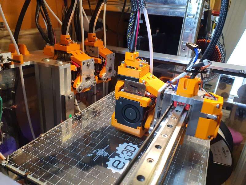
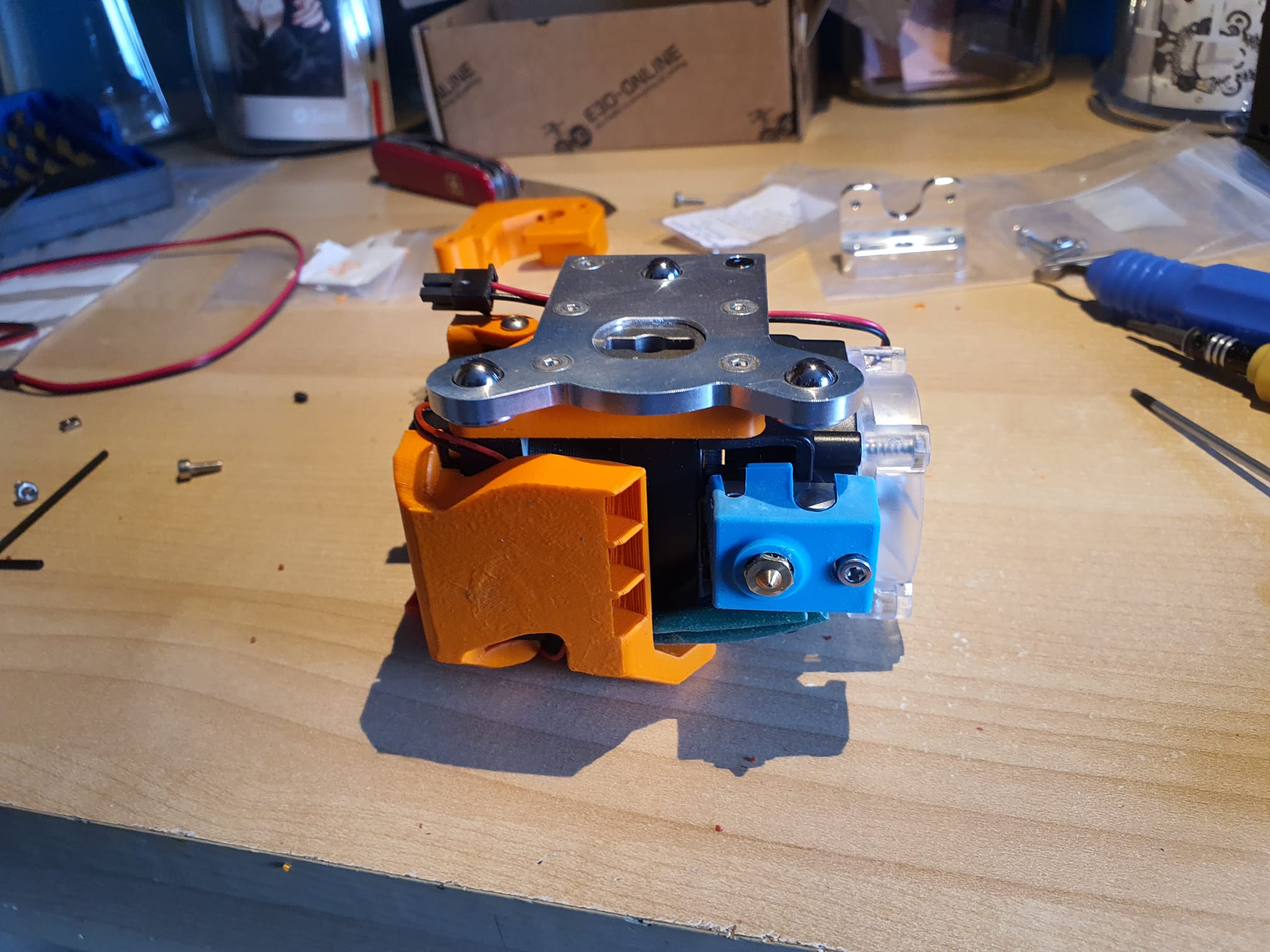
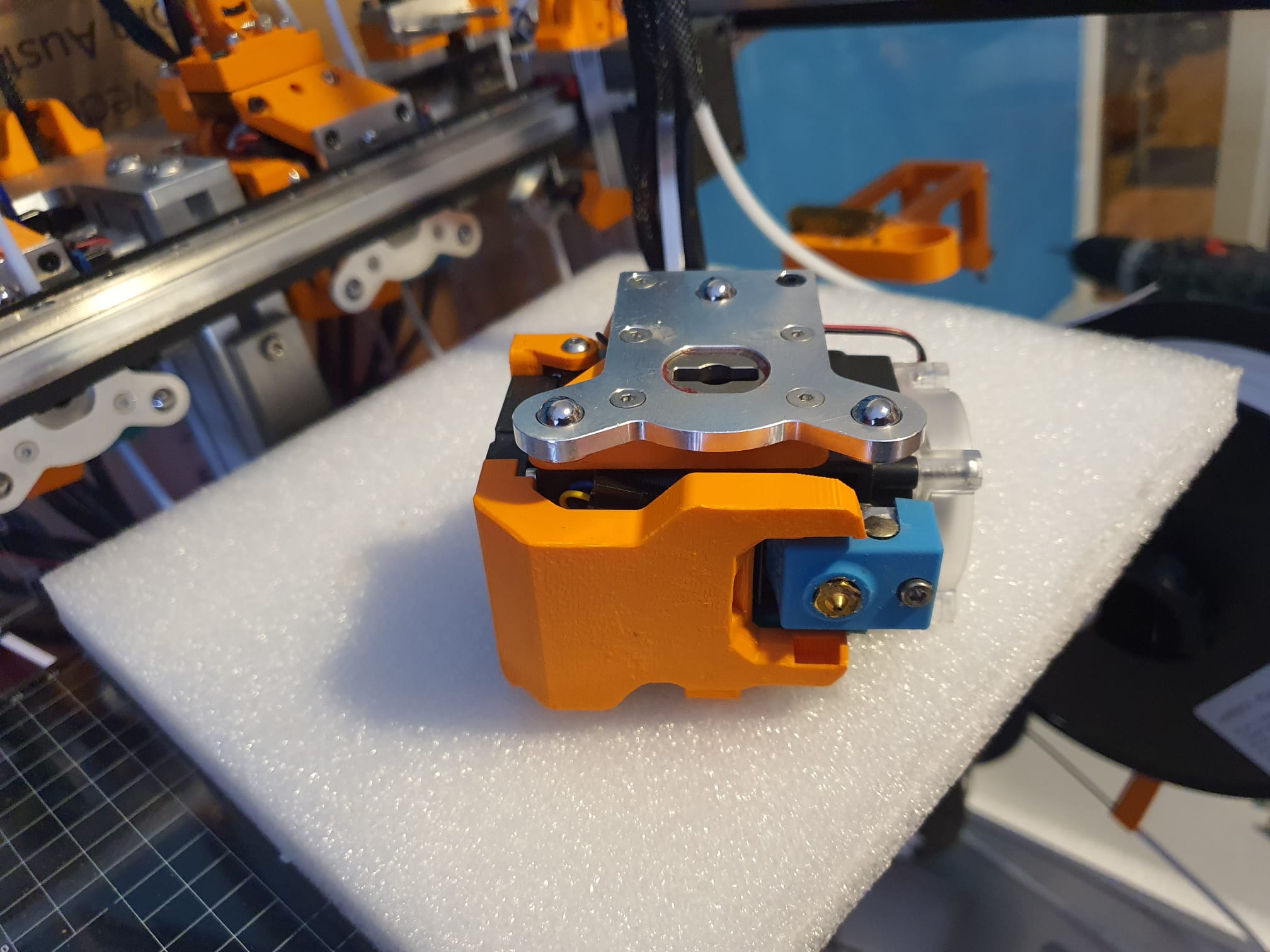
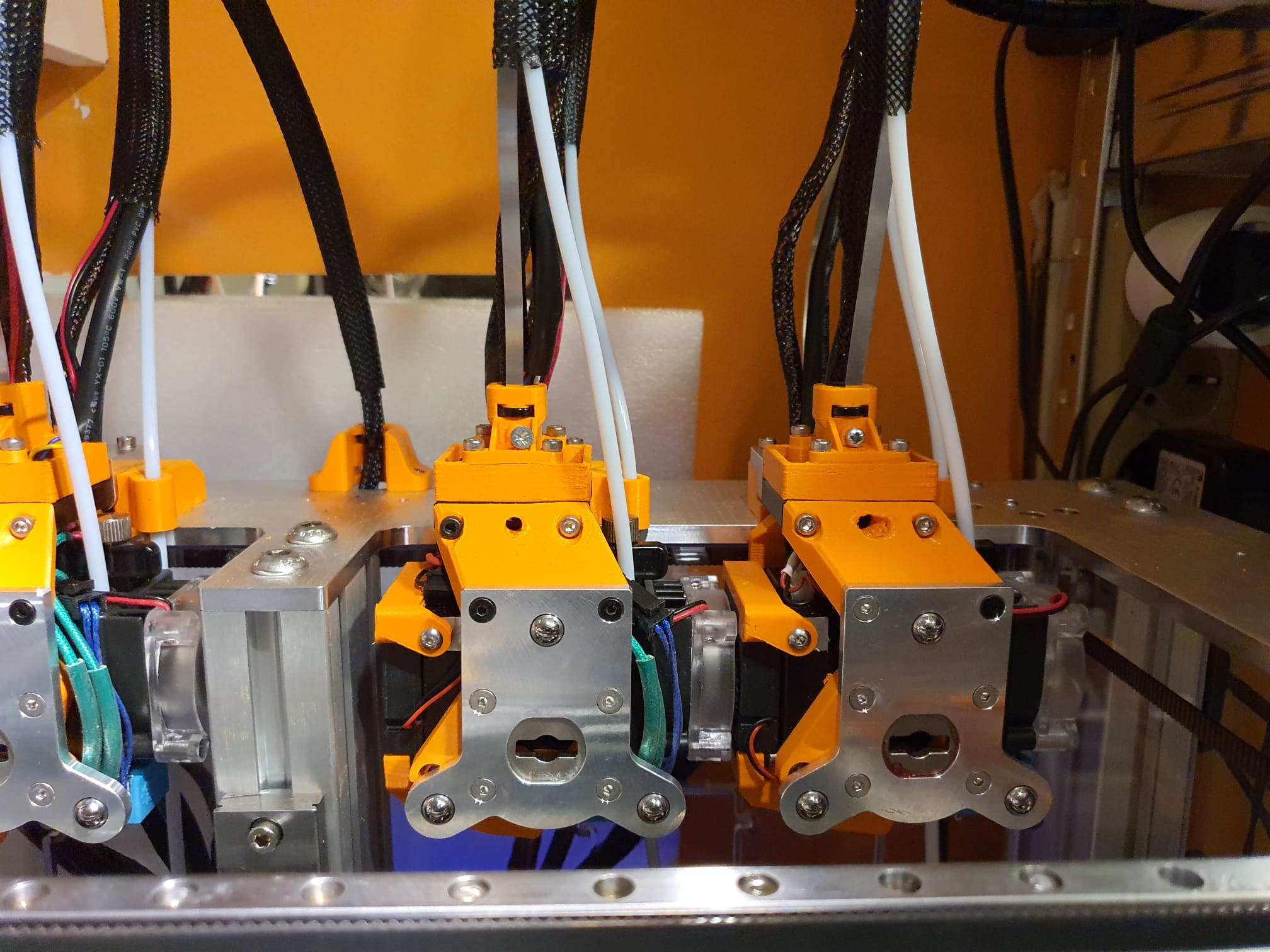
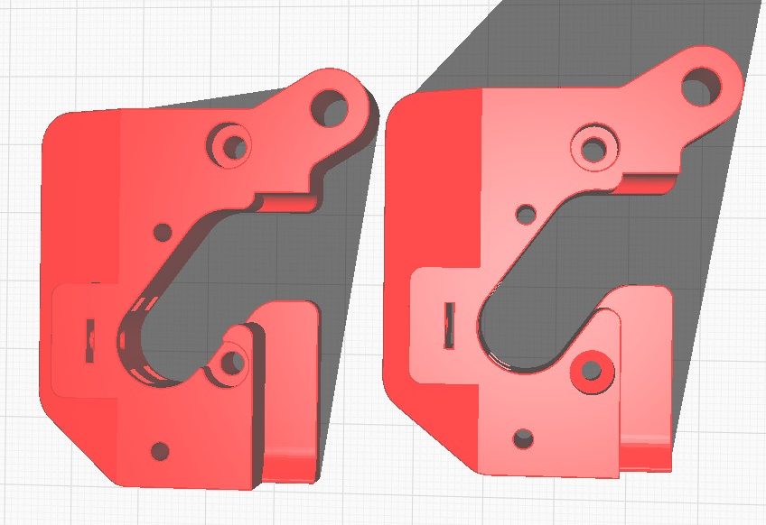
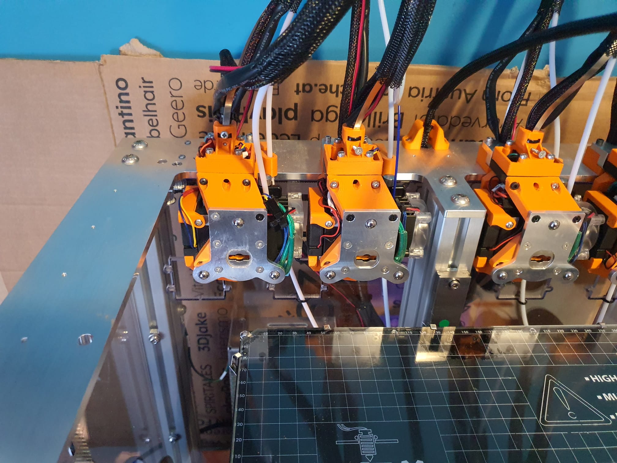
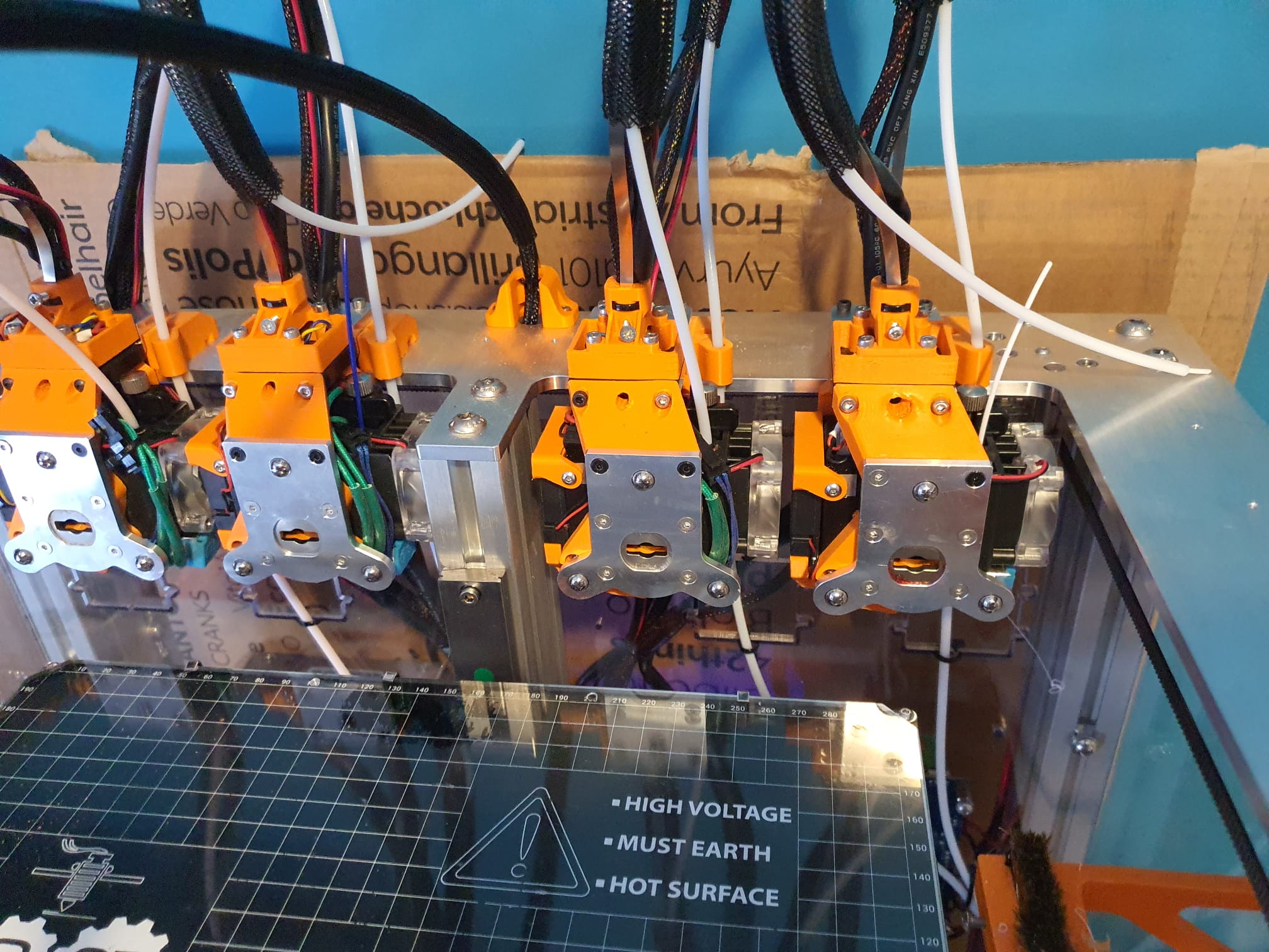
Tool T2 en T3 (3e en 4e van links) zitten bij de standaard bouw op ca 1.5 mm van elkaar waardoor de toolfan van T2 vrijwel geen lucht meer kan aanzuigen. De rechter tool T3 komt met de nieuwe aangepaste adapter 3 mm naar rechts, waardoor de linker tool T2 weer lucht kan aanzuigen met de doorzichtige fan en het koelblok van T2 kan koelen van de Hymera Direct Drive extruder.Met deze aangepaste adapter schuift de betreffende tool 3 mm op, waardoor je ten opzichte van de linker tool 3 mm extra ruimte krijgt.
Daarmee is er net genoeg ruimte gemaakt voor de toolfan van de links naastgelegen tool om het koelblok te koelen.
Plaats deze adapter dus op de 2e en 4e plek bij Tool 1 en 3.
Daarmee zijn de eerste (T0) en 3e tool (T2) qua koeling gered!
Links de originele versie, rechts mijn in Autodesk Fusion 360 aangepaste versie voor de tools op positie T1 en T3 (2e en 4e).
Ik ben bezig met het kalibreren van de gereedschappen, de algemene instellingen enzovoorts, zodat ik verder kan gaan met de rest van de tools.
Daarbij stel ik altijd alle tools in op instellingen die ik afleid ten opzichte van de eerste tool T0.
Op deze manier, mocht er iets veranderen, heb ik een solide referentie.
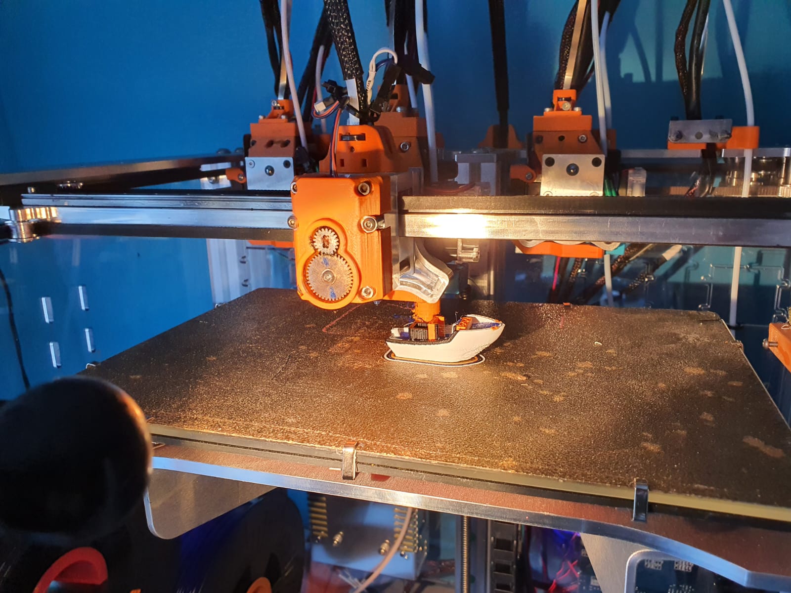
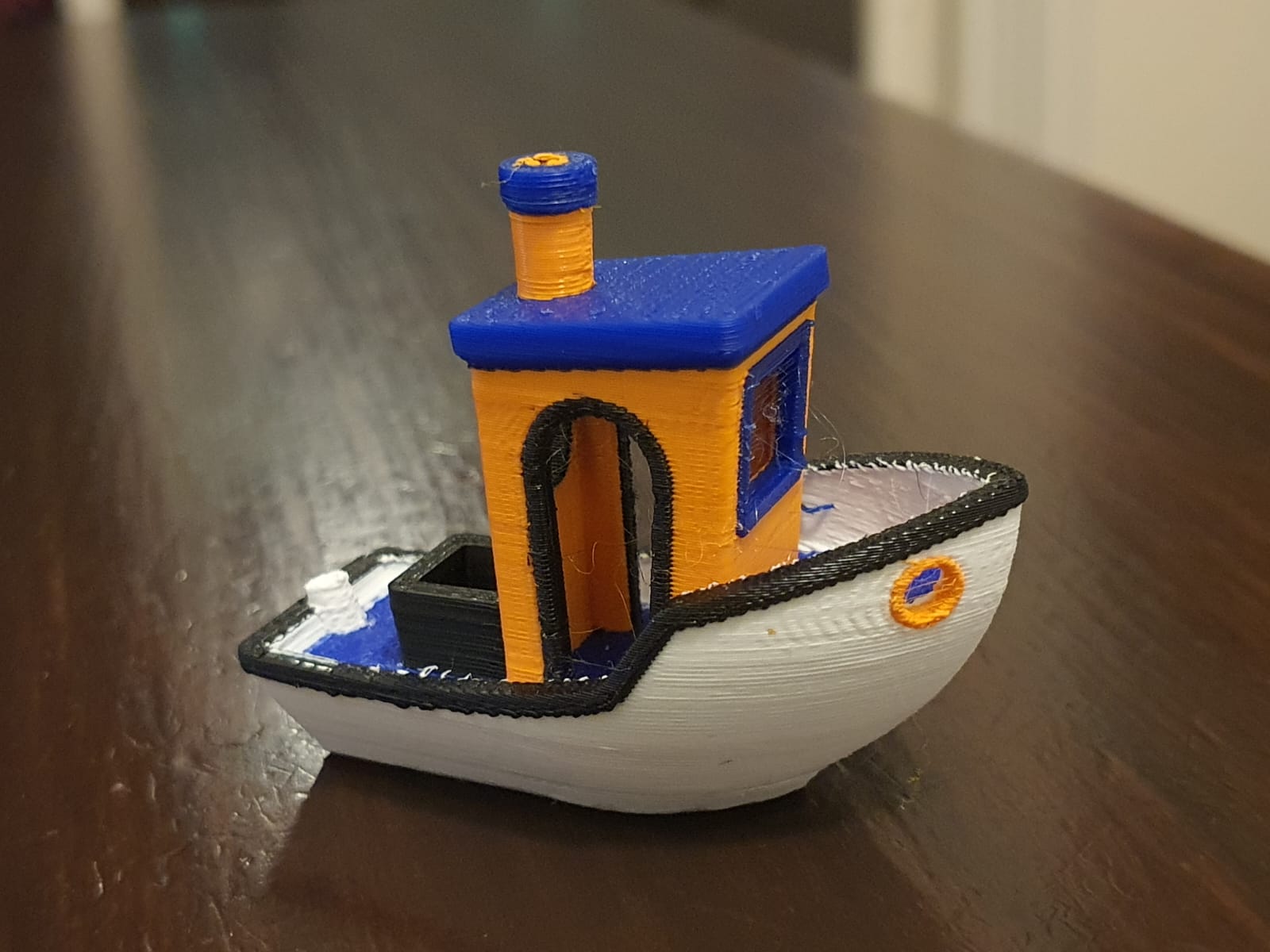
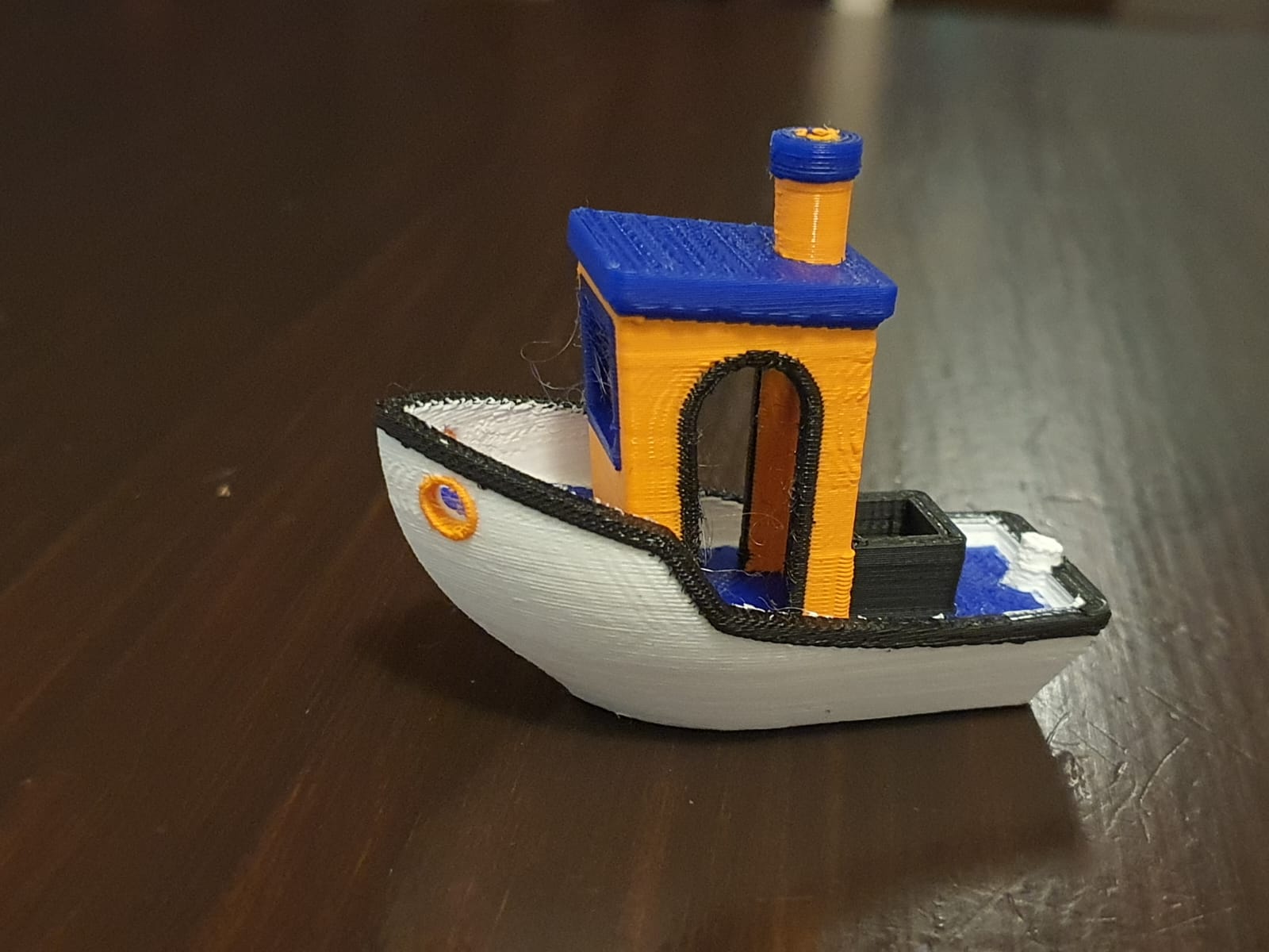
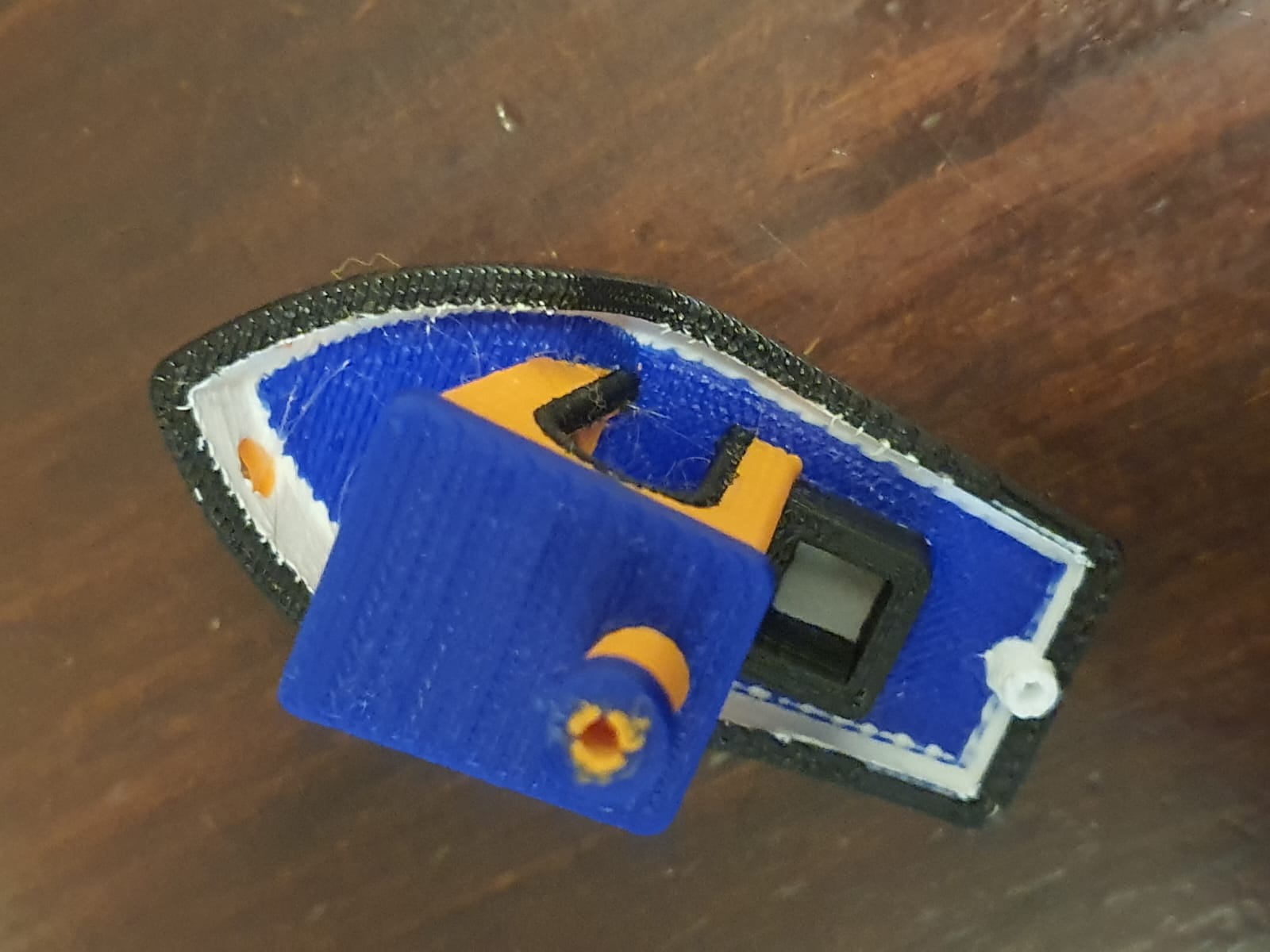
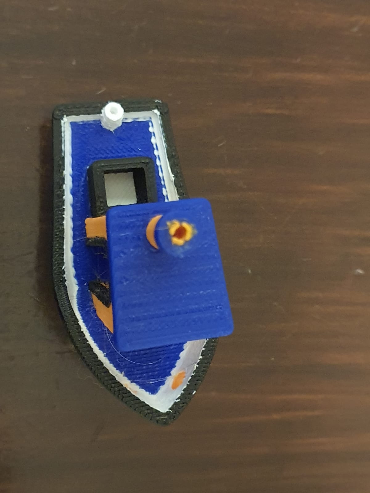
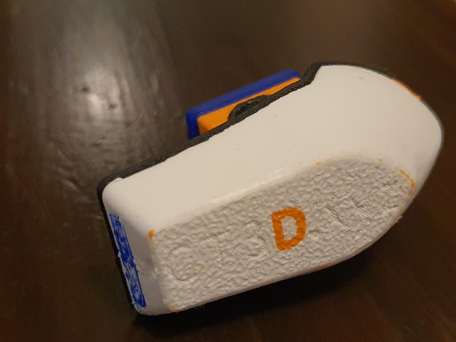
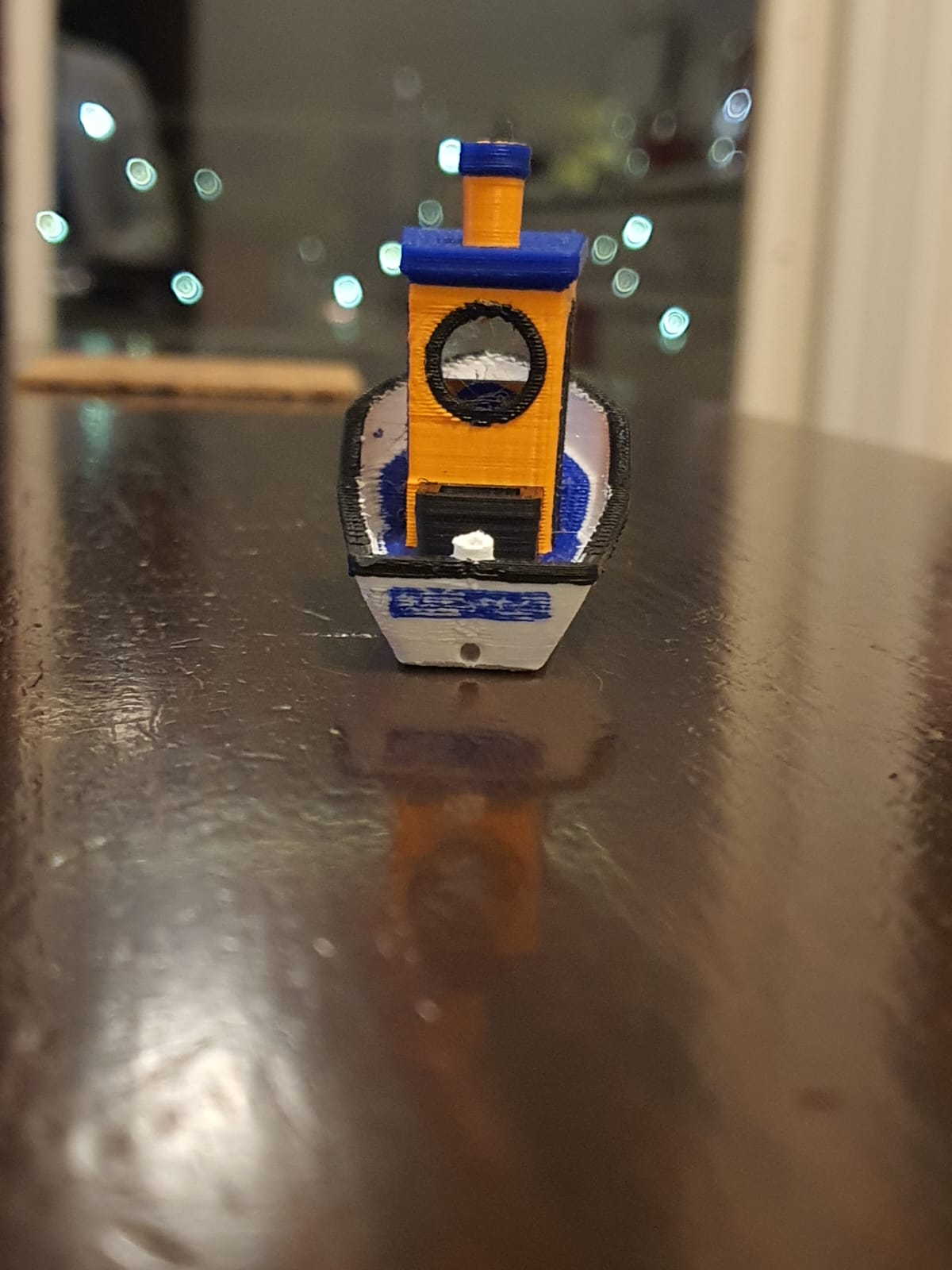
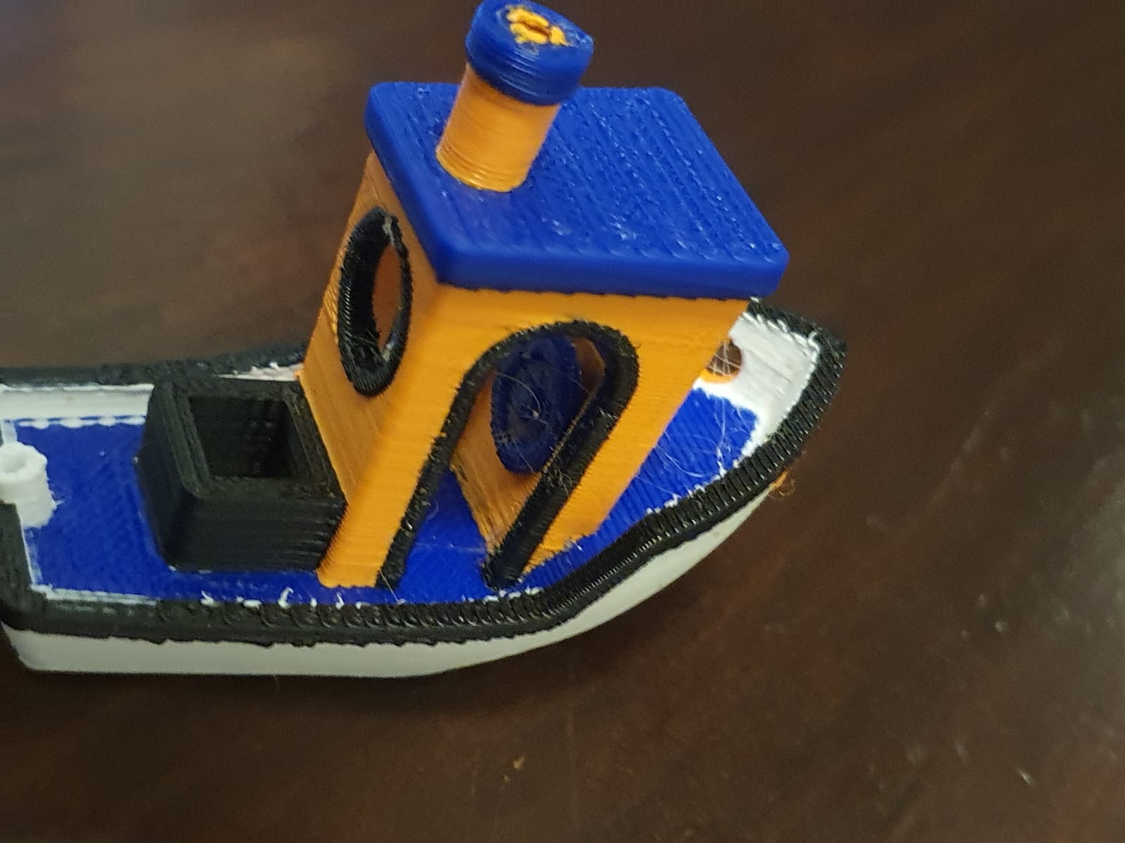
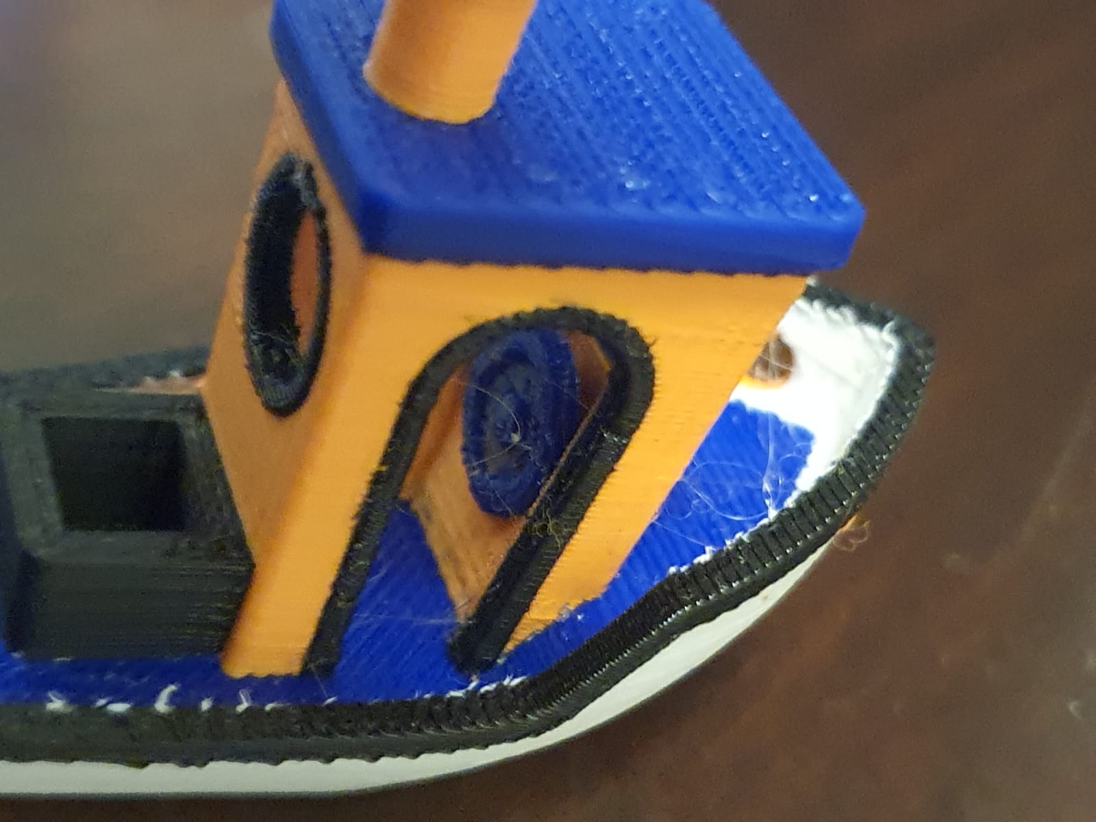
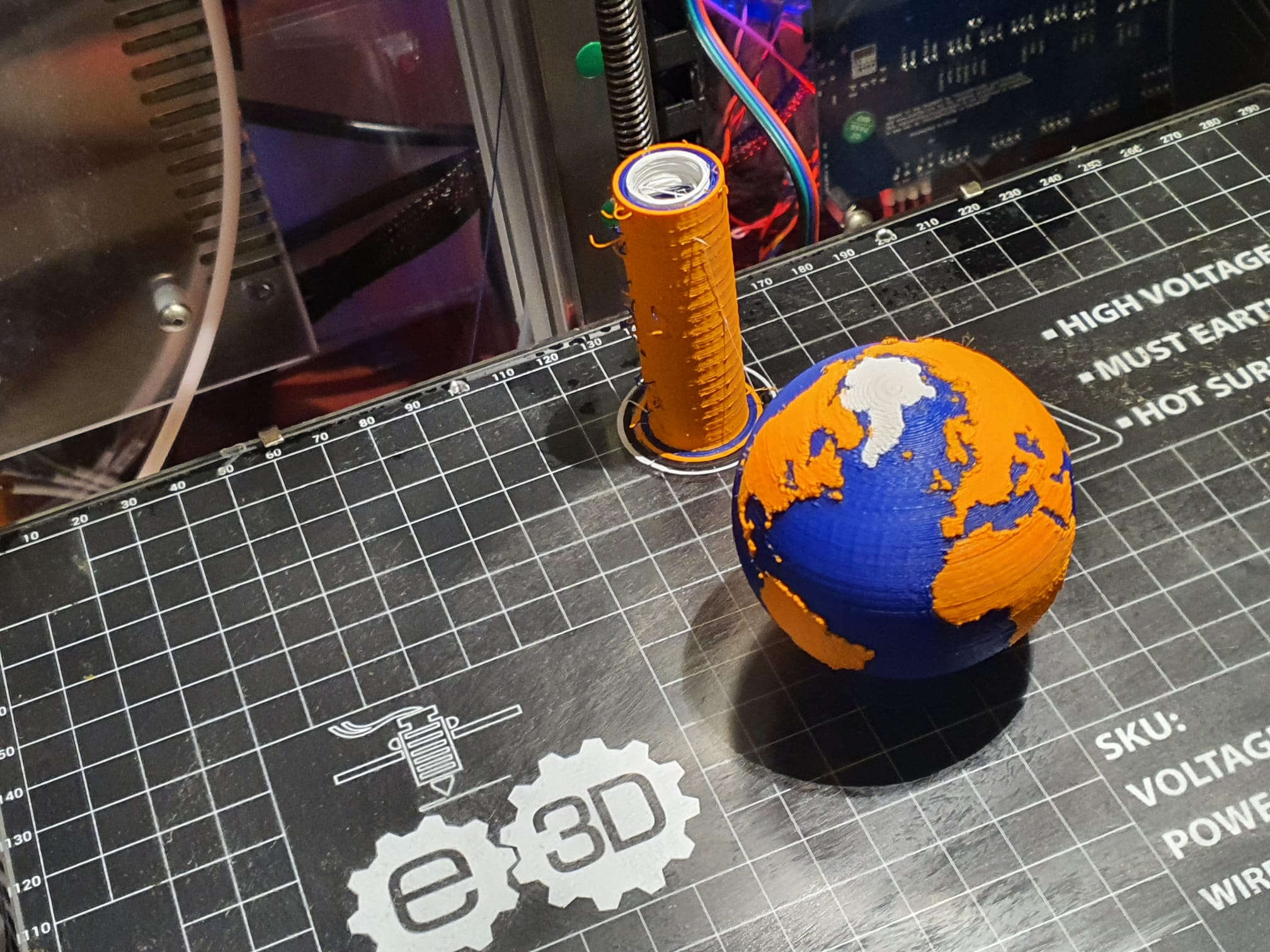
Morgen ga ik de 2 andere Hemera direct drive tools bouwen en installeren en mogelijk kan ik dan eindelijk mijn Benchy testpint printen met alle 4 de tools!