VORON 2.4 20″x20″x20″ and DUET2WIFI

Get the documentation, specs, config.g, macros and build docs

LEES IN HET NEDERLANDS

After my succesfull buildproject of a Voron 2.4 3d printer in the fall of 2020, I still wanted a really big 3d printer with a print surface of over 20x20x20 inch.

My Voron 300x300x300mm build plate size

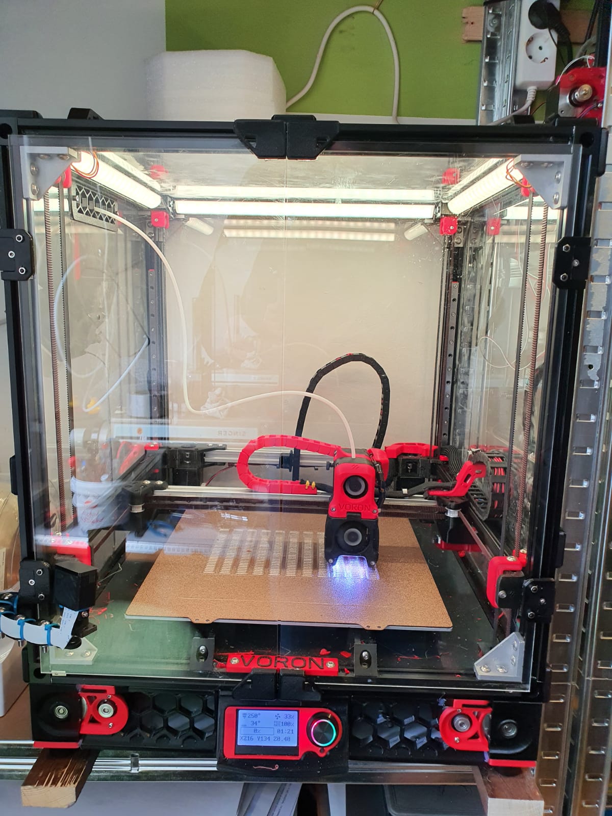
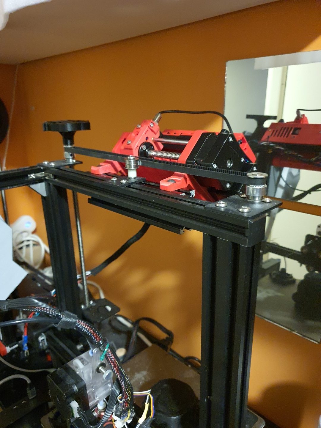
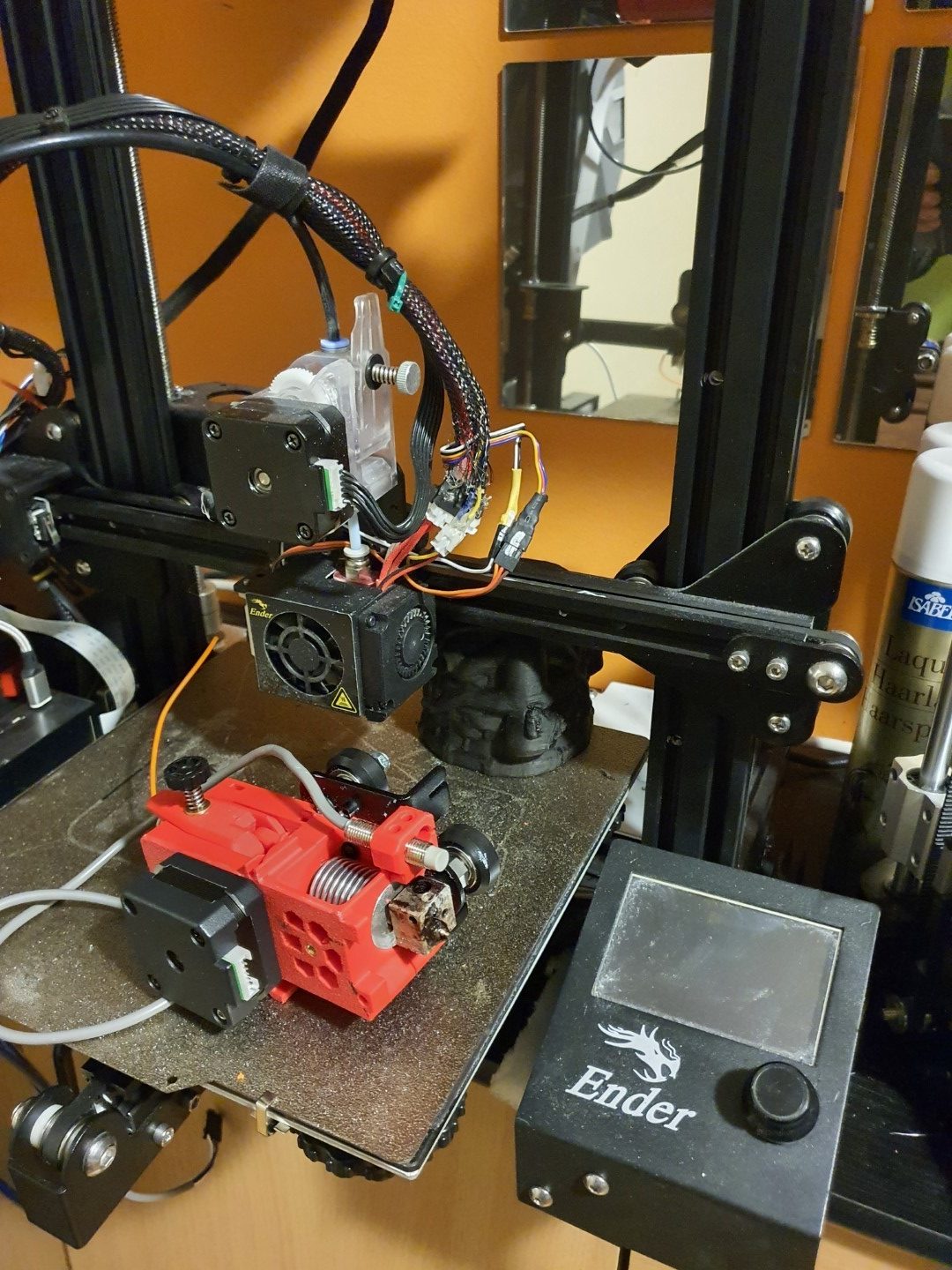
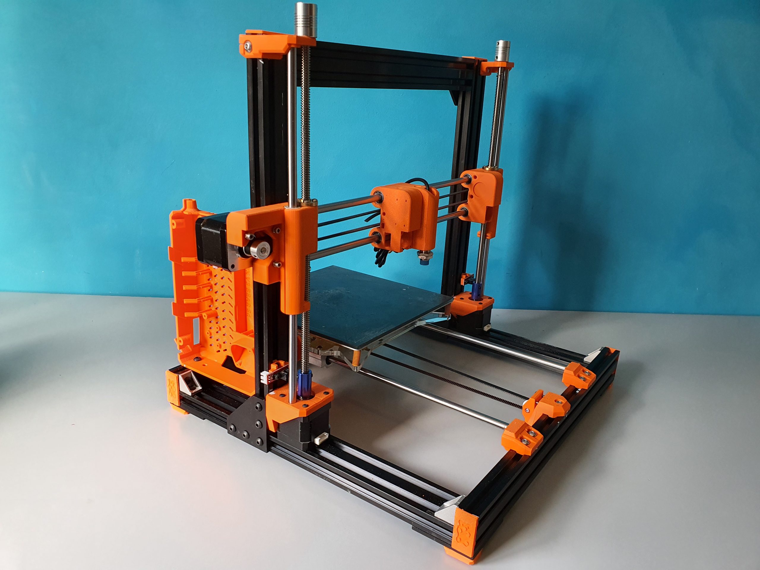
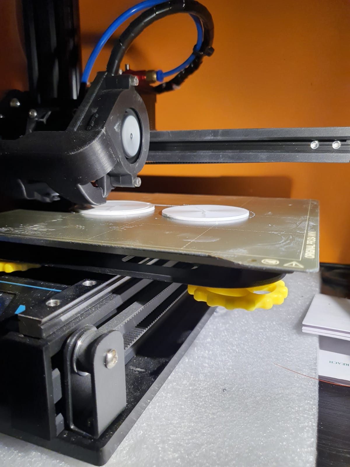
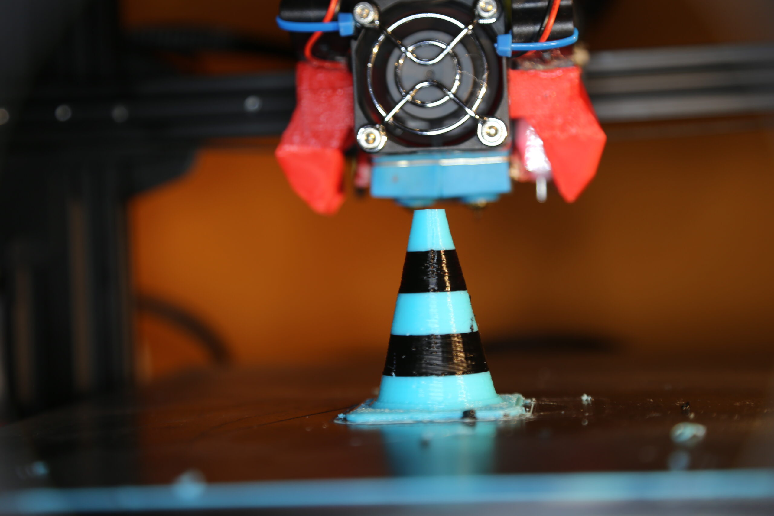
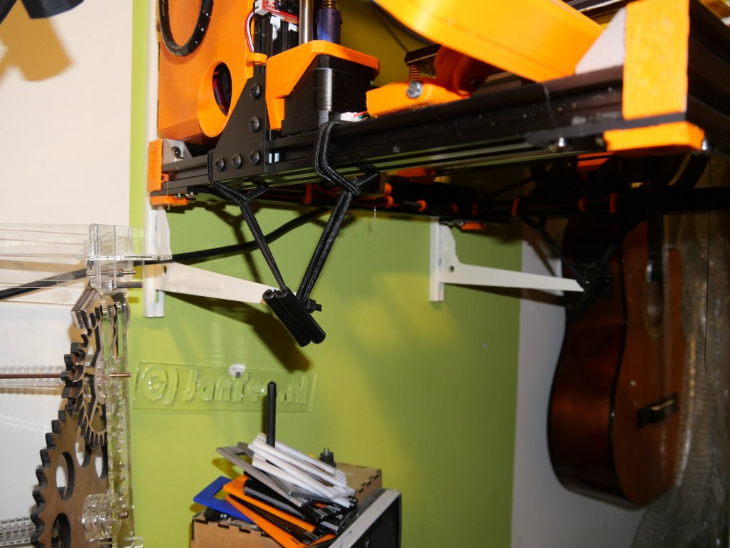
Imagine to have a print of more than double the size compared to the below picture!

During the build and at using the Voron 2.4 printer, I found the documentation on the hardware build really excellent.  But, the electronics part was scattered around several places, and although the Klipper implementation is very good I have experienced that the combination of 2 SKR 1.4 turbo motherboards with an Octopi controller does not provide enough operational stability to me. And- I feel the need to control more settings than I can do with the Klipper solution.  I think I probably am just more into the Duet and the reprap solution than the Klipper one, due to previous positive Duet – and MKS reprap experiences.

In a couple of previous builds I used a Duet2wifi, and I also experienced the add-ons for Duet2 like driver boards, PT100 boards and more hardware that is also very well implemented in the new RRF3+ firmware.

Duet wifi board , used for my dual head setup I3bear-based with sensorless homing

Reasons enough for me to choose the Duet2 and the 5-ports expansion board , or possibly an additional Duex board for my new to build Voron 2.4 ‘big 3d printer’.

At this page, I will share my progess on this build.

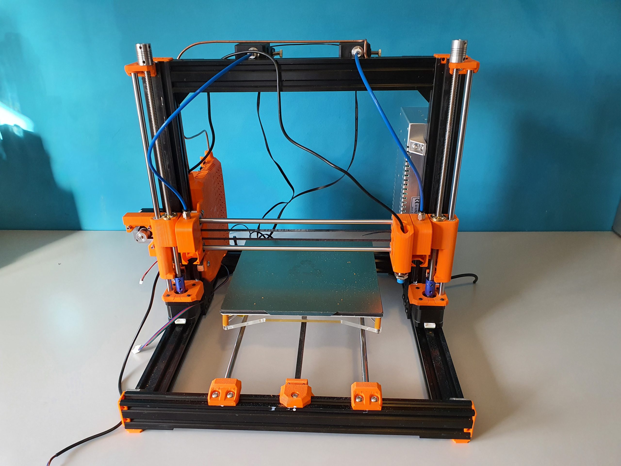
I have all required hardware laying around and since I already built a Voron 2.4, I will first focus on the electronics.  For the hardware, I still need the plexiglass sides, top and front doors.  I  do have all extrusion, bed, bed heater 230V, linear rails, all printed parts and so on, neatly stored at home.

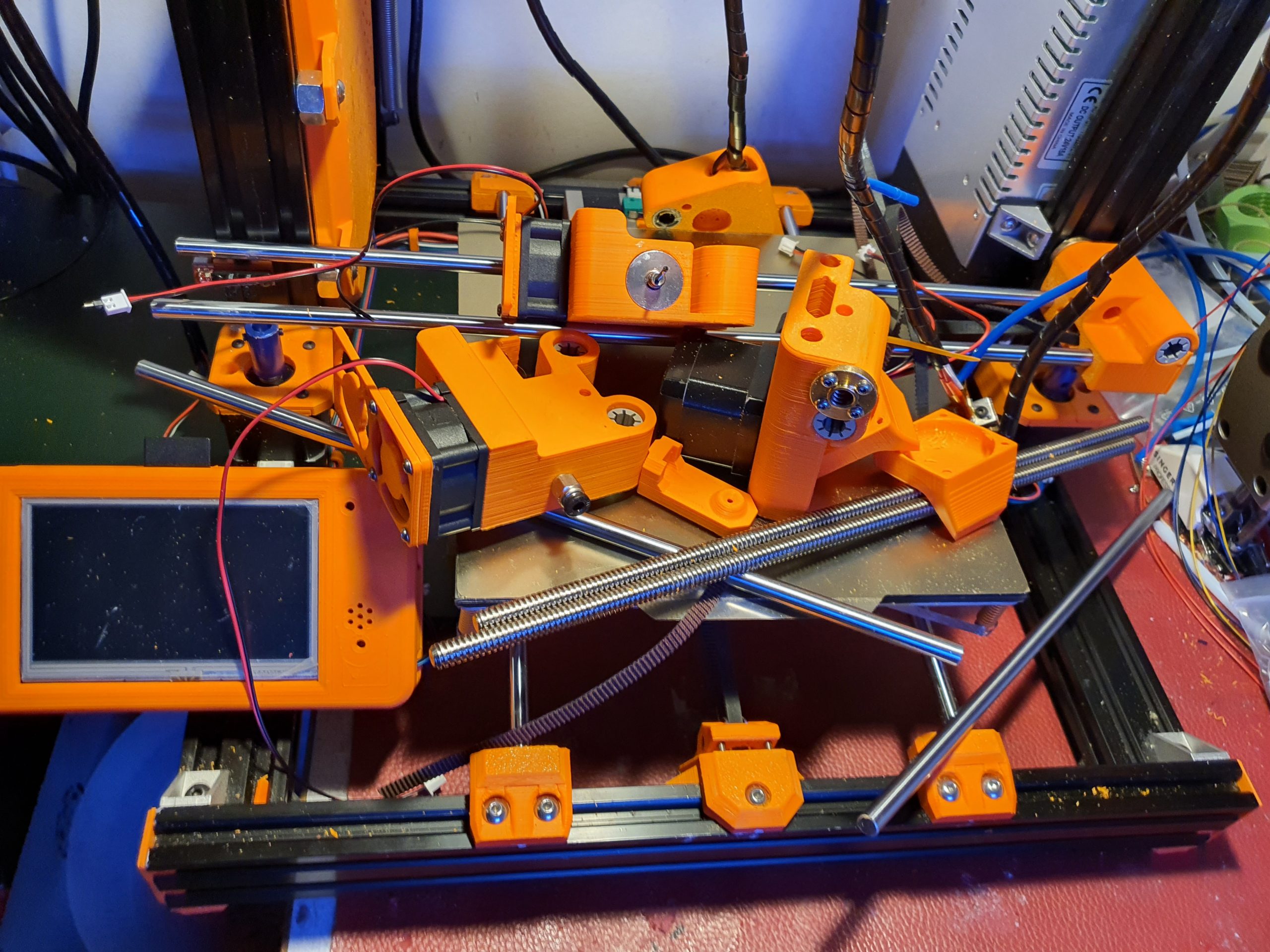
So, I am setting up the electronics to know beforehand that everything works well.  I don’t want to start building the hardware and find out afterwards that my Duet2wifi will not do the job I want it to do.

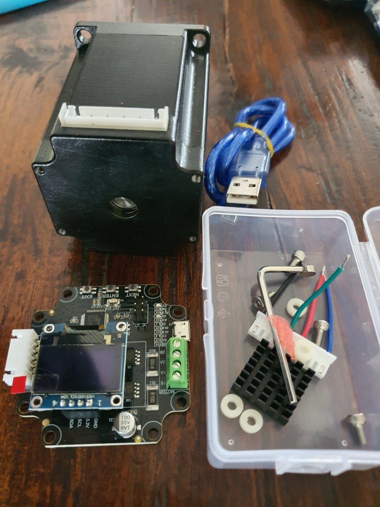
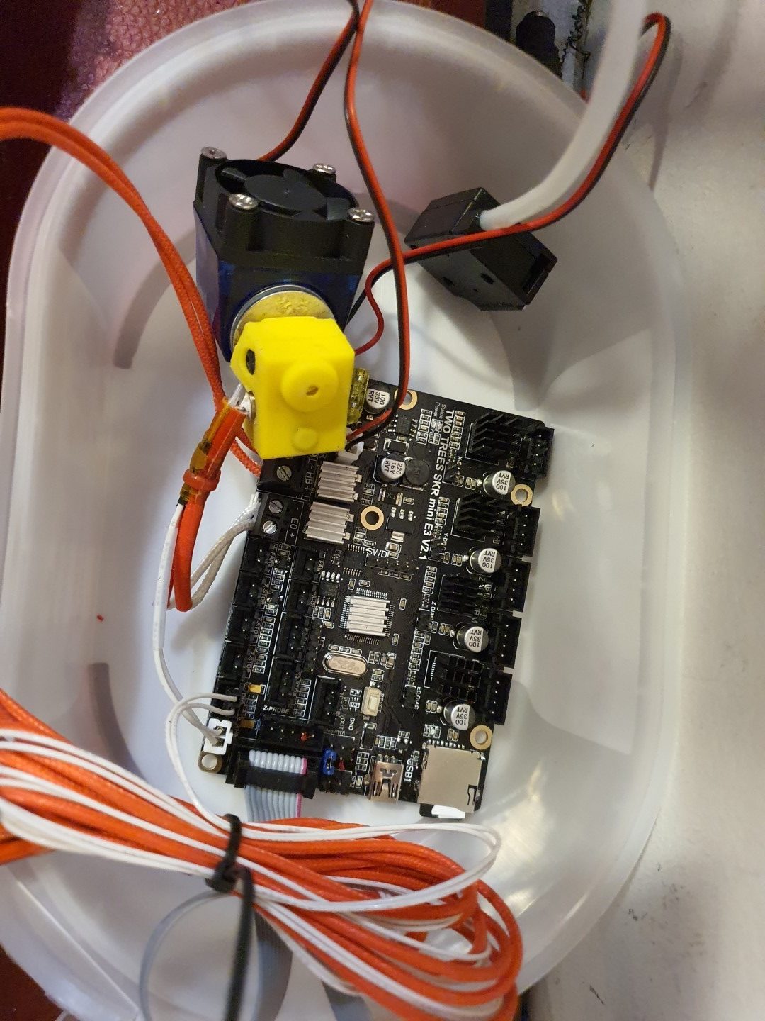
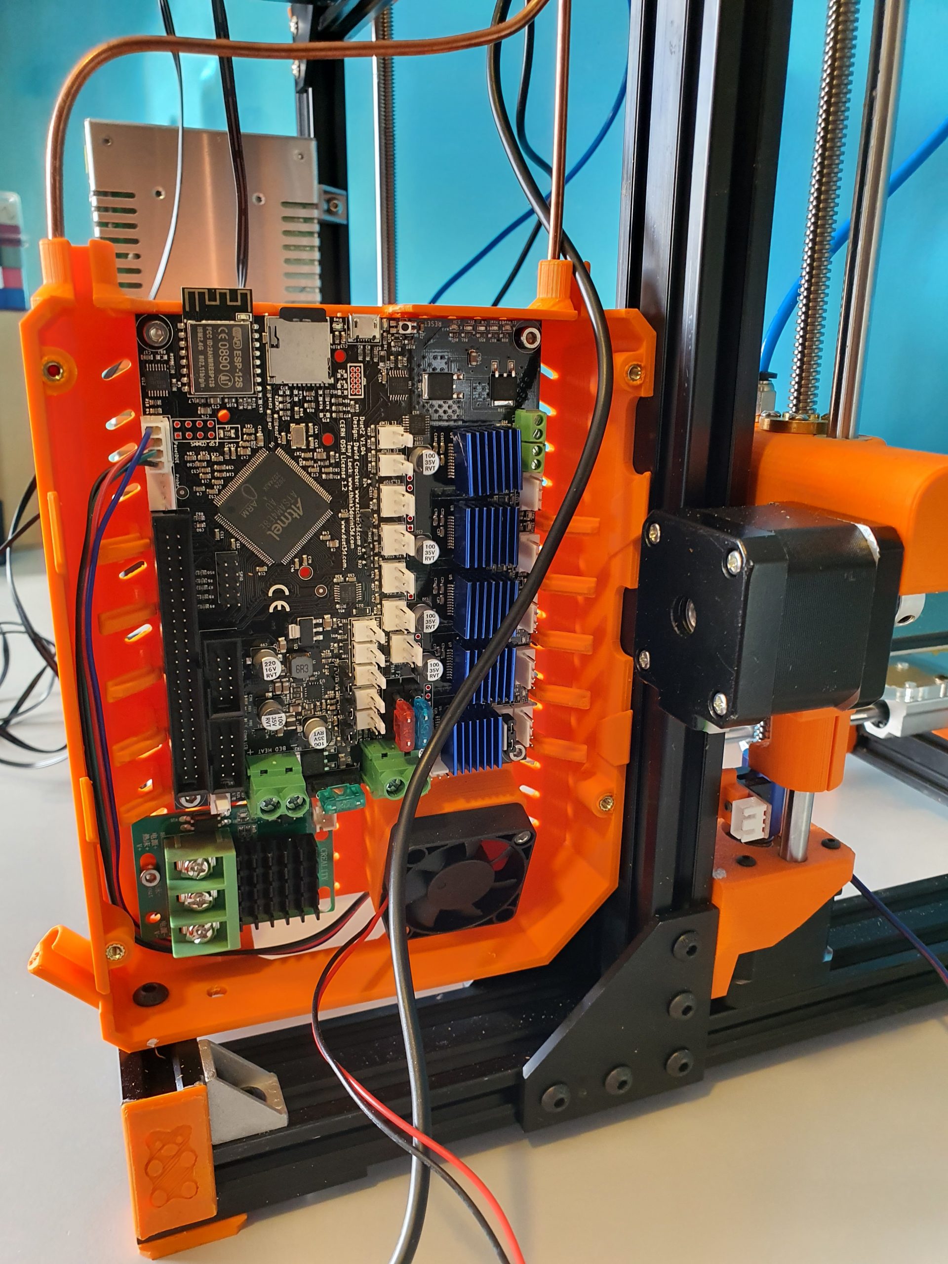
Yesterday (October 4th,2020) I put the electronics and config.g together. I used:

  • Duet2wifi board with 24V PSU and 4.3 inch TFT/LCD
  • 5-port expansion board with 4 plug-in 2209 drivers V3.0
  • Z-switch mechanical
  • X-and Y end switches (hall-effect)
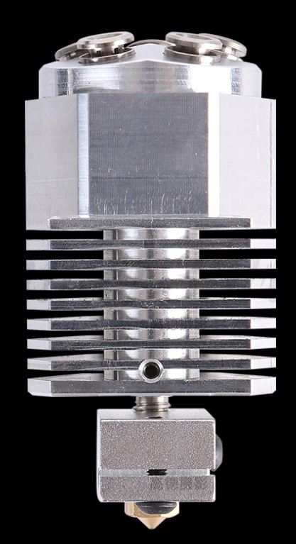
  • Hotend 24V with NTC connected including tool’s fan (I am missing the PT100’s interface board, have ordered one but I did this before so should be no problemo)
  • Hotbed simulated with another hotend including NTC
  • Stepper motors connected to X(0),Y(1) and 1 x  stepper on the expansion board Z(5) (Driver5)

The Duet2wifi board is a Chinese MKS clone with electronics version 1.02 which works fine.  The expansion board is also a Chinese one, but this is a bare-bone  implementation of the 5-ports driver add-on board that comes without drivers.  the nice thing about this add-on board is that drivers can be plugged in directly.

The Duet2 came with firmware 2.1 installed.  To get to FFR3.1, you must first install 3.0 and after this, you can move to 3.1…  be aware!

After updating the paneldue and the Duet2wifi board, I activated the wifi and put the ssid and PW in. (This procedure goes via USB between PC and Duet, using a terminal emulator like YAT)  This is a bit tiresome but given the security you get from it, I feel it is OK.

The settings that are needed to get the Chinese expension board to work are not too difficult.  Add the Z-drives, and change some other settings. On top of this page, you can download the latest doc with all info I have, and a direct download to the adapted config and macros is available in the documentation.

The rest of the build including photos will be here later!

Update 3-2021: I recently built 2 other 3d printers using Duet2wifi boards: a cartesian I3 with independent extruders and a Delta 2GS.  Not much time to work on the big Voron.  I also just rebuilt my Geetech A30M  (330x330x400mm build size) from the smartto board to Duet2wifi, Check ik out on this site!

I will probably not build the big Voron 3d printer after all,  and if I don’t, I will rebuild my existing Voron 2.4 300×300 from Klipper, octopi and 2x SKR1.4 to Duet2wifi+Duex.  That will be interesting and achievable.

Since I am currently running 10 different 3d printers, my space is getting cramped in the house. I don’t want to expand into another room.  One should be enough. Having more printers gives me the best possible fit of a specific  filament type per printer.

The Voron is due to its perfect prints with ABS really only used for/with ABS or nylon.

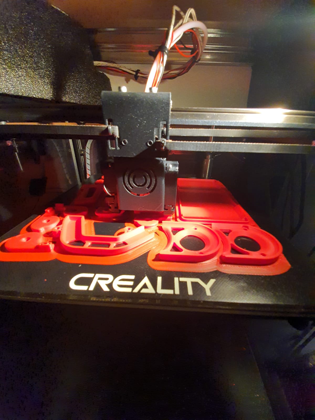
The I3Bear dual carriage works best with dual PLA or PLA&PVA.

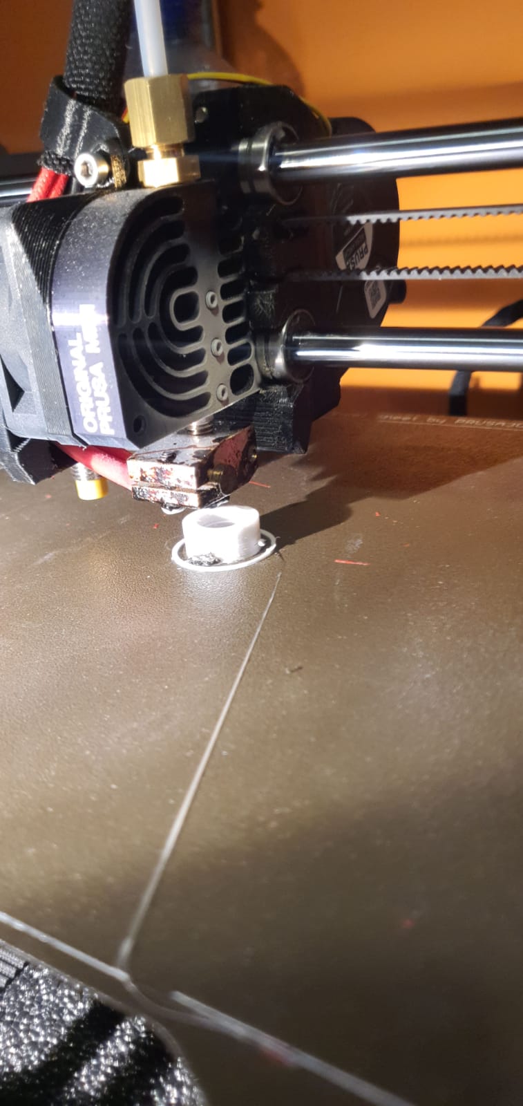
The Prusa mini works perfect with PETG

The I3Bear solo goes perfect with PETG or PLA.

The A30M & its mixing extruder goes perfect with PLA and/or PETG

And so on….

Our 3d printers, managed by OCTOPI and Duet Web Controller

Above: Our Dual Bear I3 dual color 3d printer with independant carriages, this one does not run octopi and is remotely managed by Duet Web Control (DWC).

Above: The Voron 2.4, dimensions 300x300x220 mm

Prusa Bear I3plus with mods like dual Z axis control. This printer runs Duet and  DWC.


Kingroon Kp3S heavily modded with new firmware and tool fan. This printer runs with Octopi for remote management.


Twotrees Sapphire PRO with new firmware, also with octopi.


Voron 2.4 for Nylon and ABS printing, with external exhaust and 300+ degC printhead, bed up to 150 degC.  Also runs octopi.


Prusa i3 mini original, the production monster for PETG. Also on octopi.


And the Twotrees Sapphire pro, our perfect printer for fast production, also on octopi.


And the multicolour completely rebuilt Geeetech A30M dual head printer with a new Duet2Wifi motherboard, dual Chimera heatblock and direct drive extruders.  This one runs Duet with DWC instead of Octopi.


Magnetic dual parking extruders reprap I3 Bear with Duet2wifi and sensorless homing

My most recent and probably last build from scratch is the dual carriage I3-based printer as shown in the below picture, in the building phase.  This printer can be used either for 2 colors or for printing with soluble support PVA filament.

I decided to use sensorless homing for this build due to problems when using endstop switches.  When using endstops, problems may come up because f.i.  homing to the left means that the left tool will be parked against the endstop, should you use endstops.  Same on the right hand side when the right hand tool is parked.  I encountered difficulties that the driven sensor carriage in the middle can then get into an unknown state (or position) when both tools (carriages) are in the parked position.

If you home one of both Tools with sensorless homing, the status of the sensor carriage is always automatically known.  So, since the XY position of the center (sensor) carriage is known you can always do a Z-homing at any given X-Y position and you can also do G32 and G29 without the need to carry T0 or T1 along.  And- you can easlily reset an unknown status of the sensor carriage by homing it, either left or right.

Get my build plans and Configuration files for Duet2wifi HERE

The box at the left rear is for the Duet2wifi board.  The 24V fan-regulated power supply is already positioned at the rear,  right side.

The main challenge with this build was to get the settings perfect for the dual tools.

It took me 2 months before I got it to work perftectly for both PLA and/or Petg.

As with my previous dual color dual nozzle builds, the basics is very simple. Just define 2 tools with 2 heaters, 2 temp sensors, 2 fans et cetera.

I already envisioned the approch with the slicer(s): All offsets are done ONLY in firmware, NOT in the slicer! As far as the slicer(s) is/are concerned, the nozzles of Tool0 and 1 are at the same (X0/Y0) offset.

For the Duet, the only addition in the slicer is an M0 command as stop command for the printer.  Define 2 nozzles of 1.75mm without any offset and you’re done in the slicer.

Then, you will need to set everything in your config.g at the tool section like XYZ offset and so on.

I decided to get T0 as reference, and set everything to 0 there. X=0, Y=0 and Z=0.  Then, measure the differences at T1 versus T0 with calipers to start with and inport these values in the T1 toolsection in config.g.

Start a testprint and measure what to amend, take little steps and the metrics are done!

But- the hard part is- as I experienced- to get good prints without blobs and unexpected stringing, both incoming as outgoing (into and out of the printed object(s).  Drying the filament also helps a lot!

In the end, I just took the same approach as with the tool settings: As little as possible retraction settings in the slicer and all except the basic print retractions are now in the configuration files that are called upon Tool changes tpre.g,  tfree.g and tpost.g (for T0 and T1).

This means that you can play with retracting and extruding of filament length and speed directly at, during and after Tool changes.  And- in my experience it is all affected by the type of filament you use and the temperature you are at with the hotend. Also, the fact whether you use a lower temperature during waiting has great impact.

In my experience, you should finetune the config settings for the mentioned settings per object and per type of filament.

Therefore, I decided to used this printer for only 1 goal and make the settings perfect to accomplish this goal.  Right now, I have optimized this printer to print 1) PLA from 123print in the Netherlands, of a specific type and 2) PVA from the same supplier.  This gives me the possibility to print complex objects with soluble supports and it works extremely well at doing this!

PM: I also added LED lights on top of the printer as an integrated feature.  This makes use of a heater pin as GPIO (with a M42  P [pin] S[value intensity]) command), like the solenoids that I use to catch the carriages T0 and T1. To come from the 3.3V and max 1mA from the GPIO pin to the required 24Volts, I used small mosfet boards.  All programming is done in the Duet’s config and macro files, view the below example of my stop.g file which is called from the slicer’s stop setting: M0.

; stop.g
; called when M0 (Stop) is run (e.g. when a print from SD card is cancelled)
; Also called by slicer end gcode by M0
;
M400 ; Finish move queue
M117 Cool down ; Update the LCD screen with “Cool down”
M83 ; Extruder relative mode
G1 E-2 ; Retract filament 2mm for both extruders !!
M106 S255 ; Fan at 100 to cool nozzle and bed
M104 S0 T0 ; Extruder T0 heater off
M104 S0 T1 ; Extruder T1 heater off
M140 S0 ; Bed heater off
G28 X ; Home X
M220 S100 ; Set speed factor back to 100% in case it was changed
M221 S100 ; Set extrusion factor back to 100% in case it was changed
M42 P4 S0 ; Magnet T0 off
M42 P5 S0 ; Magnet T1 off
M104 S41 T0 ; set extruder T0 to cool down
M104 S41 T1 ; set extruder T1 to cool down
;M568 R41:41 S41:41 ; set standby and active temperatures for tools 0 and 1 (or single M568 T0 R41 S41)
M116 ; wait for Tools actions as specified in above M568 instructions
G90 ; Absolute positioning
G1 Y200 ; to get objects removed easier, move bed forward
M106 P0 S0 ; Fan L object T0 off
M106 P2 S0 ; Fan R object T1 off
G28 X ; Home X
M84 ; Steppers off
M98 P/sys/ledflash.g; Perform execution of ledflash.g in specified directory
M42 P6 S0.008 ; Led light setting almost OFF
M117 Jantec=done! ; Update the LCD screen with “Jantec=done!”

G1 X5 Y5 ; Move to corner
M140 S{print_bed_temperature} ; Set bed temp
T1 ; Select extruder 1 (or 0 depending on how your printer is set up)
M104 S{print_temperature} ; Set extruder temp
M116; Wait for temperatures


Please donate $1 to my paypal account if you use (parts of) my developed materials so I can continue to share nice stuff for you to download


Our 3d printers, managed by OCTOPI OR Duet’s web-based app

Above: Our Dual Bear I3 dual color 3d printer with independant carriages, remotely managed by DUET’s webinterface

The Octopi solution works with a Raspberry PI, and on it the Octopi firmware.  The device you set up on your wifi and you connect it to your 3d printer’s USB. Then you have a web interface on the Raspberry’s IP address that allows you to manage all the things about your connected printer.  All the settings like temperature, mesh, and basically anything else you can manage through a local LCD.  And- you can upload your jobs to the raspberry and start/manage and adjust temperature and such.  What I really like is that you can connect a raspberry camera and follow your jobs.

The Duet I find in use and possibilities more pleasant. because in addition to everything that the octopi can, you can also modify the system files online.  And printer updates can do, directly in the firmware.  Moreover, you do not need a separate box because the Duet2wifi already has everything on board.

The disadvantage is that you can’t attach a camera to the Duet. There is a possibility em an IP camera to integrate into the DWC, Duet’s web based remote app.  And such a wifi IP camera is easy to make yourself with a cheap esp unit.


Above: The Voron 2.4, dimensions 300x300x220 mm

Prusa Bear I3plus with mods dual Z axis control


Kingroon Kp3S heavily modded with new firmware and tool fan


Twotrees Sapphire PRO with new firmware


Voron 2.4 for Nylon and ABS printing, with external exhaust and 300+ degC printhead, bed up to 150 degC


Prusa i3 mini original, the production monster for PETG


And the Twotrees Sapphire pro, our perfect printer for fast production


And the multicolour completely rebuilt Geeetech A30M dual head printer with a new Duet2Wifi motherboard, dual Chimera heatblock and direct drive extruders


Mellow FLY-CDY-V2 motherboard

recently (3-2021) I have been setting up my new 3d printerboard from Mellow, an STM32 board that is named FLY CDY V2. It is (almost) fully compatible with Duet2Wifi and also uses its wifi-based 3d printer management system DWC.

The config file I made for this setup is HERE

The FLY_CDY_V2 board comes completely empty so I added the firmware.bin in the /sys directory, after I had an empty SD card filled with the clean reprap directories and -files.

Next to the firmware.bin. also a board.txt is required to be available in /sys with some settings, with the following content:

//Config for fly-CDY
board = fly_cdyv2
led.neopixelPin = D.15;
//wifi pins
8266wifi.espDataReadyPin = E.10;
8266wifi.TfrReadyPin = E.12;
8266wifi.espResetPin = E.11;
8266wifi.serialRxTxPins = { D.9, D.8 };
heat.tempSensePins = { B.1 , A.3 , C.4 , D.14}; be aware that D.14 is not a temp pin but a heat pin, is this wrong??
stepper.numSmartDrivers = 6;
serial.aux.rxTxPins = {A.10, A.9};

This board.txt is already OK for 2209 drivers and for the use of the neopixels output.

In the pdf that is provided by Mellow on the Github page for the reprap STM32 boards, section FLY-CDYV2, everything is explained as to get wifi up and running,  configure config.g et cetera.  

In my config.g everything needed to work properly is already done, as is with my board.txt.

I made the config for a.o. a  Cartesian printer with single X,Y,Z steppers and a triple hotend with 3 extruders, 1 heater and 3 nozzles.
Included is: Neopixels, BLTouch, 3 filament sensors on the X,Y- and Zmax inputs, active fans for hotend tool on fan1 and object on fan0
If so desired, sensorless homing is possible with the correct driver boards. In this version, 3 optical endstops have been used on inputs xmin, ymin and zmin.
Retraction is set OFF in this firmware by default, but may be swiched ON to make the triple hotend drip less (2 mm retract and -0.5 extrude without Z-hop), do experiment with these settings!
Please be aware that some pin names for the FLYCDYV2 board differ from the Duet’s naming convention like “bed” versus “bed-heater” et cetera.
Plus, some typical Duet2wifi extensions are NOT available like the GPIO bus.
The FLYCDYV2 has some interesting standard extra’s though, like the BLTouch connector with power, driver pins and Z probe pins, the Neopixel connector AND the 6 driver slots and 3 extruder heaters/sensors/fans!
It is quite simple to change this setup to a dual Z axis with independant Z-motors and either single extruder or a dual setup, single or dual nozzle, mixing or non-mixing.
Please see my complete ready-to-go config directory setups for this board HERE to get you  started! 

Also: Check my CNC Indymill running with the FLY-CDY-V2

Please donate $1 to my paypal account if you use (parts of) my developed materials so I can continue to share nice stuff for you to download


Dual magnetic parking extruders I3 Bear Duet2wifi build and Config files

My dual carriage I3-bear based 3d printer is working very well.

On this page I share my latest configuration files, my build experiences like the used STL’s , schematics and so on. 

Hope you enjoy!

Be aware that the tool settings in config.g are set including relative X, Y, Z values for this build so DO NOT put this in your slicer! 

And- you need at least RRF3.3.1 for reprap FW and for DWC. 

The sensorless homimg also requires knowledge of config settings and the good news is that the Duet2wifi has this all managed by the reprap firmware.  No switches needed or complex jumper settings!

Tip for printing the parts: I used ABS for all parts. Use at least a printer with calibrated XYZ values for your specific filament. 

Do a testcube first and apply any needed adjusting to your slicer’s settings like pre-shrinking settings of the endresult and so on. 

If you don’t do this, then don’t start this build. 

It is a prerequisite to get the magnetic carriage to deliver-and get the carriages from left and right of the X-axis. 

Therefore the movement needs to be free of unneccessary friction. 

And– if you use sensorless homing any additional friction on any sensorless homed axis might lead to unintended stalls.

I added a dripstop to the left and right hand sided X-carriages, made of some thin tinned plate.

It is positioned so, that a little tension is put on the nozzle tip in the parking position. It really works very well!

The config.g for this build and the Duet2wifi is HERE

The Sys directory for the dual carriage build and Duet2wifi is HERE

The Macros directory for the dual carriage build and Duet2wifi is HERE

The build plan for the 2040 extrusion frame is HERE

2.1 version Prusa i3 MK3/MK3S Bear Z Extended 459mm Black kit 2040  Extrusion Anodized After Cut Prusa i3 MK3 Bear Profile Frame|3D Printer  Parts & Accessories| - AliExpress

The STL files for the X-axis carriages and carriages are HERE

All other needed STL files for the printer are HERE

The Duet’s case and 4.3 inch Paneldue’s case are HERE

The page of the working printer is HERE

The build plans for the electronics and Duet2wifi wiring schemes are HERE

Please donate $1 to my paypal account if you use (parts of) my developed materials so I can continue to share nice stuff for you to download


Penta extruder on A30M

Today I received my 5-in, 1-out hotend, non-mixing  air cooled with 1 nozzle and 1 heater//temp sensor.

I will install it on my A30M with the Duet2wifi board+extension board (5-fold with plug-in drivers). The A30M already has independant Z-stepper motors.

The Duet2wifi has 5 stepper ports, and the expansion board also has 5 stepper ports.  X,Y,2xZ, 5 Extruders is a total of 9 so this will indeed fit!

I will make new wiring for the 5 extruder steppers on top of the A30M frame with 5 bowden tubes to the hotend.  Since the hotend is non-mixing, this will be a  simple task to get into config.g.  For the slicer- it will also be easy. Just add the extruders to a total of 5 pieces. Add the correct filaments/temps/ no offset so set offset X and Y to 0..  The work will primarily be in  the tool changing files for T0-T5 where retraction- and extruding  settings will be needed.

For the hotend, I have a new setup available that allows me to quickly change the nozzle.

This will make it possible to use this setup for all kind of applications.

Voron 2.4 Core XY build

My experiences with CoreXY printers are excellent, so I chose a VORON for my home-built COREXY printer with a print size of 300x300x300 mm.

Developed from a large community, the VORON is one of the best and most reliable 3D printers.  And this printer just looks really good!

Via AliExpress, Banggood, Reichelt, aluminiumopmaat.nl and plexiglas.nl I ordered all the stuff, according to the bill of materials I could download from the VORON site.

I printed the PETG parts on the Prusa mini at 0.15 fine.

The ABS parts (red and black) were printed on the Twotrees Sapphire plus.  It took a lot of ‘tweeking’ before the ABS came out well but in the end I got a nice result!

Printed parts for the Voron 2.4 300In the end, rebuilding is not really self-building and it is more based on ordering and assembling than getting to work with the saw and drill yourself.  Also the necessary 8(!) linear rails of 350mm, bearings, gears, belts, motors, electronics and so on have been ordered and the rest of the necessary stuff has been printed (25-8-2020).

For the control part I have chosen one PI Raspberry PI 4B 4GB and two pieces of SKR 1.4 turbo motherboards, according to the VORON recommendation.

Building the Voron 2.4 with the afterburner Beta1 hotend combination is illustrated by the following pictures.

Gantry ready:

Gantry of my Voron 2.4 300Housing and skirts underside with Z-motors yet without the gantry mounted:

Frame of my Voron 2.4 300

Electronics positioning underneath my Voron 2.4 300

Below: The 9 mm drive belts of the 4 Z-axes placed:

Halfway the building phase of my Voron 2.4 300

And the assembled base plate with the rails and controls, power supplies and so on (printer turned over):

Cabling and electronics of my Voron 2.4 3000: 2xSKR1.4 turbo with Klipper, Raspberry PI and Octoprint with Klipper

We are still waiting for the bearings for the Alpha and Beta drives in the gantry.  These bearings are used to make a tension roller per 2 pieces.  I had originally bought idler bearings for this purpose, but the diameter of the collar of these bearings is just too large.

Too bad but then I have to work on the Raspberry PI4B in combination with 2 times SKR V1.4 turbo motherboards.  The PI will make a new config.bin via Klipper for the SKR V1.4 motherboards so the PI can drive both SKR boards at the same time.  On the main board will be Alpha and Beta and the extruder plus the extruder heater, on the other (Z) board the 4 Z-motors and bed heater.  By itself a Duet with expansion board could have been an option too, but the Voron designers made it with the PI, Klipper and 2 SKR boards.  And I try to stay as close to the design as possible . -)

Below: Threading the straps, no picture used.  Just start somewhere and you’ll end up right.  Oh yes, also changed the sensor in the config from NC to NO..

Below: In addition to the 24Volt 200 Watt hotbed nevertheless also added the 500 Watt 230V.  With only the 24V version it took more than 20 minutes to get to 110 degrees Celsius…

Old:

And new— no PID run done yet..)

Below: The steel plate is placed on the sticky magnet sheet.

Below: First print….  I had to search for the Z offset adjustment and the extruder turned the wrong way around.  Also the gantry leveling took some thought, you actually have to make the basic setting with a ruler, otherwise the leveling takes a long time.  Nice is that a bed mesh leveling is not necessary anymore, but of course it can be done.  You turn a home and because the nozzle always calibrates the Z on the mechanical Z endstop, and the gantry does all the leveling, you always have a good first layer.  Unless the bed warps but with such a thick plate that seems almost impossible. Just to be sure, I did include a bed_mesh profile in the config.g.  By the way I just used a 24 V aluminum hotbed as a base because my 8 mm 310×310 plate turned out to be a cut plate instead of sawn.   And a cut sheet turns out to be non-flat on the cut sides by default, unfortunately.  Flattening costs more than a new plate, maybe that will come sometime….

And with enclosure, camera and the TOP LED’s:

Afterword:

In practice, I fixed a few more minor flaws, including:

Extruder tuning.  The donor extruder turned out not to pick up the filament properly.
First I tried to put a ring in between the left side of the shaft, but then the nylon gear on the right side of the shaft gets tight and the housing can’t be closed completely anymore….
I ended up using a spare set of dual drive extruder gears and swapping the set of gears.  With that, the filament was properly aligned with the running path of the gears.  See the picture how it was at first:

Misaligned filament path in Afterburner extruder

Hotend tuning
After the PID runs of hotend and heated bed, my chosen assembly of the custom ED6 heater block, the heatbreak pipe and the cooling element turned out not to fit together properly.  The result was that when the filament was extracted, a thick piece was always stuck at the end.  This was caused by the heatbreak pipe not fitting tightly on the nozzle.  There should be no play between them.  I completely demounted the filament and screwed the heatbreak pipe 2 turns less into the cooling element with red threadlocker.  Let it harden for a day and then I assembled the rest.  By the way, I also mounted the teflon version of the heatbreak pipe in stead of the titanium version.  The tintanium version was to my experience a bit too stiff.  Or my filament was too old or inferior.  In any case, after the modification, everything works without problems.

Hotbed, TPU and ABS
To print TPU and ABS without brim or skirt without warping I bought a magnetic PEI steel plate with coarse profile.  It really works perfectly. Both ABS at 110 degrees sticks nicely and TPU at room temperature sticks nicely too.  And the removal is also without problems.  Occasionally I spray a little hairspray on the plate but I don’t think that lacquer is really necessary at all.  It is meant to make the removal easier.

Tension of the belts
I tried getting the belts at the same tension, this was not that easy.  Finally I ended up with a mechanical way of measuring tension after putting 1 at my desired tension and comparing this as reference with the other to be compared belts.  So, for the Alpha and Beta belts I first did a ‘good feeling’ setting and then I used my old trunk scale weight device to measure the tension when pulling the belt A. Then, I used the device to measure at the same place for B. And I repeated this for the 4 vertical belts.

Alignment
Aligning the machine is also a bit of a challenge…
You must assume that your frame is square and straight.  You have to check this thoroughly.  Both vertically, horizontally and diagonally.  Then you can adjust the gantry. Loosen and remove the A and B belts.  Or do the alignment BEFORE placing the belts.
Fix the horizontal position of the Gantry otherwise you can’t align at all. Place 4 equal distance blocks of about 10-15 cm under the sliders of the vertical linear rails on the lower 2020 profiles, in the 4 corners through which the gantry rests stably. I have placed position holders under all MGN9 vertical linear rails afterwards so that the rails cannot slide in the 20×20 V profile.  If you use ‘regular’ 20×20 extrusion profile you don’t have a problem because there is enough ‘meat’ left for attaching your rail to the profile.  With V-profile, the groove is a bit wider and it is very difficult to mount the rails neatly without tools in the groove.  My frame is of V-rail profile and the gantry of plain 2020 profile.
The alignment of the gantry I started at the back.  Loosening all screws a bit, including the screws of the convex connectors that hold the gantry to the linear rails.  By the way, I see some builders placing these screws with multiple spring washers.  I’m going to do that too…
At the rear of the gantry, push the gantry completely against the rear.  There should be no gap between the XY joints and the frame.  PS: Leave the endstops off for a while at this action!
While the gantry is sitting against the back, tighten the XY joints and the sliders of the X-axle as well. (the side of the endstops holder is temporarily secured with 2 screws)
Tighten the rear 2 gantry joints (with the convex surfaces) as well.  This fixes the rear position at right angles.
Carefully slide the gantry forward. This should be possible without any effort.  If not, check whether there is enough play (and if necessary loosen the screws) on the gantry joints at the front (with the convex surfaces).  If you still don’t have a free run to the front, your frame is not good or your vertical rails are not seated properly.  First check the correct positioning of your rails with your position tool (from the printed stock) and to be sure also unscrew the 4 screws on both front vertical rails.  Try again if the sliding of the gantry goes smoothly.  Still no good?  Then reverse the procedure and start at the front.  Try to set the gantry exactly level with the frame.
After adjusting: Test the alignment also halfway (vertically) and at the top!

Geetech A30M first use

In mid-June 2020, I started using the Geeetech A30M desktop 3d printer.
The printer can print 2 colors mixed with 2 filament geared drive units on top of the frame and a fan for each feed to the combined hotend.

A few adjustments are needed on this printer if you really want to work well with it.
First of all, I had a lot of trouble with the standard noise from the 24 Volts fan under the bottom plate, which is supposed to provide cooling for the motherboard. This fan is always running at full power.
I put a controller in between with controls on the left side, through a drilled hole. I secured the controller with 2 tie-wraps through the cooling slots on the left side. The dial just comes through the case and you can hardly see it. Most motherboards I use don’t need a fan for cooling because they are placed freely in the open frame but the A30M has a closed case so a little air circulation is necessary. Plan is to add a thermostat control so the knob is no longer needed. Later. The controller is set to the position that there is a lot of air movement but without the whirring of the fan.

Second modification is the addition of a Geeetech 3d touch on the hotend. The bracket was included with the printer, suitable for both a thick inductive sensor and the 3d touch sensor. What’s nice is that the software (or firmware, if you will) as suitable from the factory for autoleveling. Do pay attention to the correct placement of the connectors, from the front view the brown and black wires should be mounted to the right.

The disadvantage is that the firmware from factory does not really work well with auto leveling. In the middle of the hotbed everything goes fine but with larger prints I noticed that the first layer was printed very differently, so everything kept coming loose. So now I work with manual leveling while automatic leveling is possible.

The hotbed is nice and big with a workable size of 320x320mm. The print height is 420mm.

The price was over 400 Euro, and the delivery was from Germany.

I recommend everyone to secure ALL and especially to include the block hook. My one was really not assembled properly. All threads were OK but all bolts were either too tight or not tight at all. I only found this out during the first test print. I stopped and checked everything. Pay special attention to the rollers of the hotbed. It is difficult to reach them but in my case the adjustment wheels were not set at all and did not rotate. The disadvantage of such a desktop printer is that you hardly have any space under the hotbed.
The vertical V-profiles were not mounted perpendicular to the upper profile. That is difficult to repair because everything is drilled through and bolted. I recommend installing corner stiffeners at the back in the top 2 corners. I have them on order and then they can go right on.

And… what some large printers have and the A30M does not: Additional stabilization rods to the front (or to the back, that is also possible) so that the vertical profiles cannot move. Now when you apply a little force there is about 2mm of play on it, despite the solid mounting to the desktop housing.

IndyMill CNC machine

Since Corona was still around (May, 2021) , I had some time available to spend on other things than just work.

I already had an upgraded 3018 CNC-machine with a 0.5 kW spindle motor,

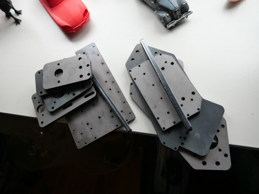
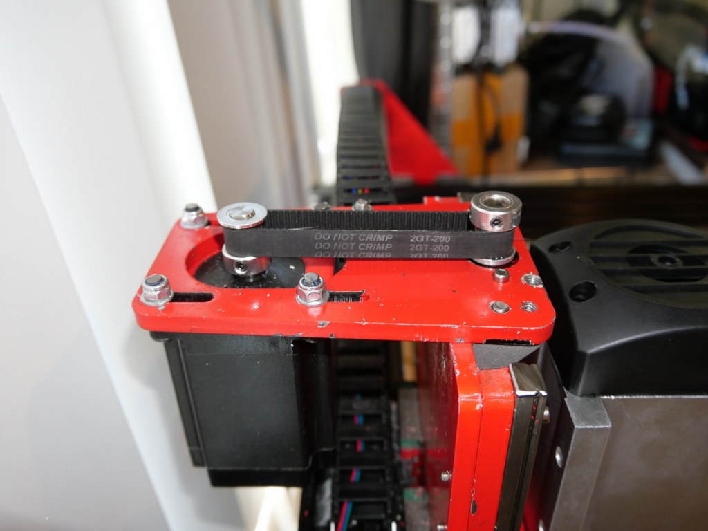
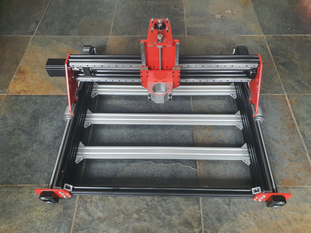
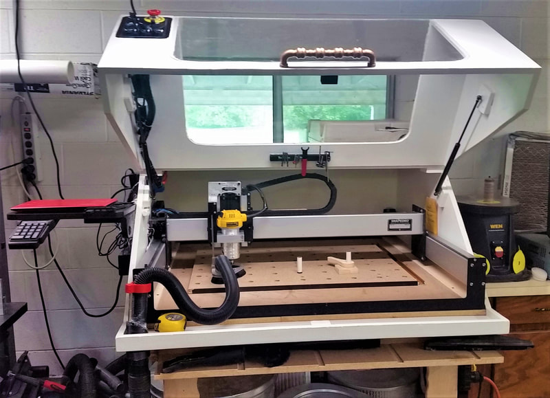
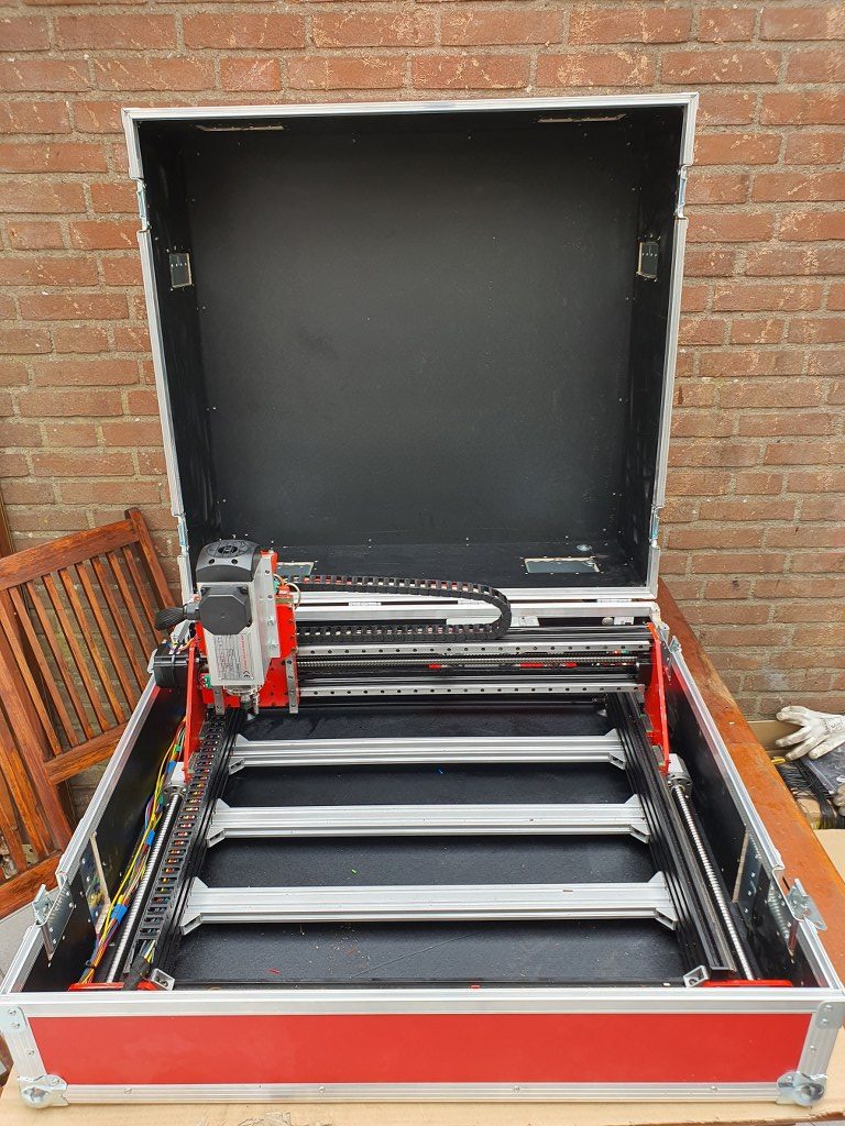
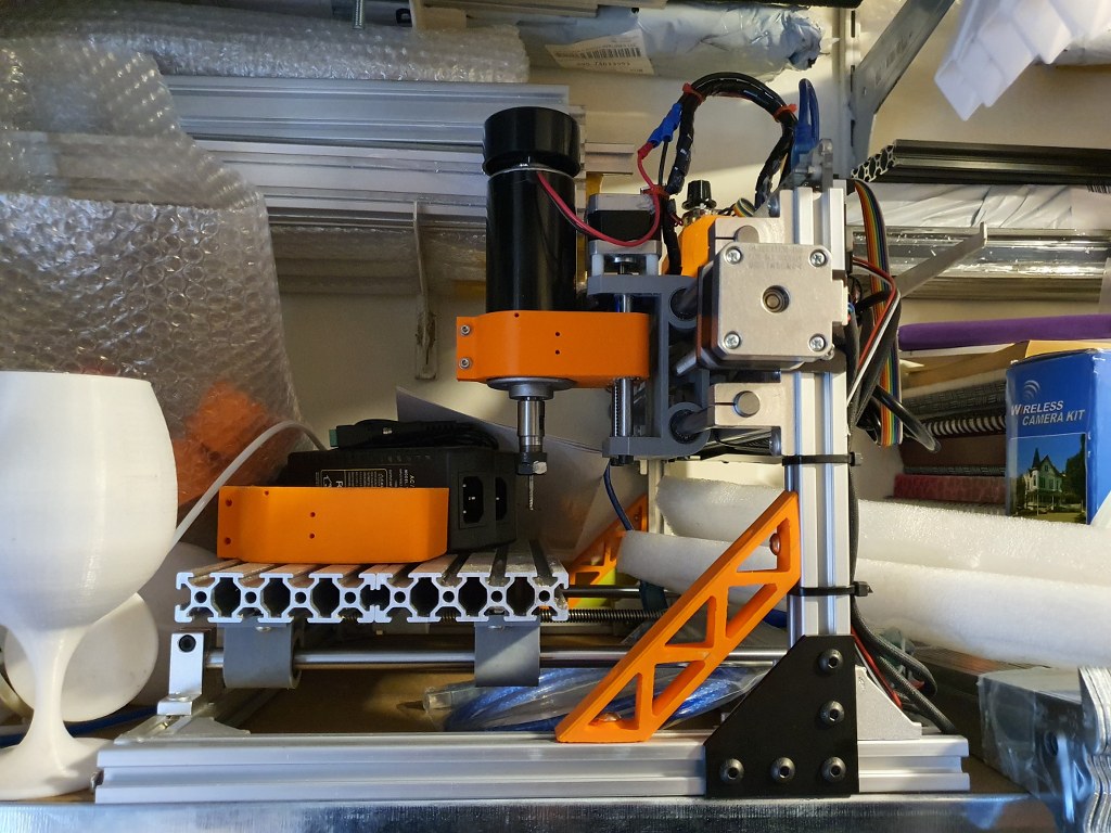
and a simple GRBL 3- axis board that works very well.  But- it would be nice to make a CNC machine that can really work with aluminium and possibly also with copper and brass.  I have already done some research in the past about what sort of CNC machine would be right for my goals. And the IndyMill CNC macine was already on my mind for over half a year.  So-last week I ordered the manual and the steel plates

for the build and ordered some other parts from Ali.  I also have quite a lot of parts on stock, from my 3d printer supplies.  The Nema23- motors and the extrusion, motherboard, drivers, power supply, switches and probes are already available.

2021-5-09; First parts delivery for the Indymill: 3 ball bearing leadscrews with kit of end bearings and screw block holders, the frequency regulator 1 phase in, 3 phase out and the 1.5 KW 3 phase spindle of 3.6 kilograms

The required printed parts are being printed right now (early May-2021). I am printing all the upgraded STL’s, latest version as these are freely available  on Thingiverse (just search for IndyMill) .  And then you see the power of sharing: the design was already great, and with the upgrades it got even better.  The upgraded versions of the mounts for the linear bearings are really a lot sturdier than the original design and the new endstop holders are very handy to have.

I roughly calculated the costs for building this machine and it was a lot cheaper than buying a similar CNC machine of this size.  If you purchase wisely, the costs for all materials can be just under Euro 1000, if you follow the original BOM and including the 1.5 KW air-cooled spindle motor with regulator…

If you want to install another board than the standard Arduino UNO with the standard Arduino CNC shield,  this can set you back an additional amount of 120 to 500 Euro’s.  I use a FLY_CDY_V2 with Mellow’s original TMC2209 stepper drivers. DO NOT FORGET to set the switches on the underside of these steppers to ON if you want to use sensorless homing!

My add-ons  to the original build:

  1. Currently I use a 10 Amps detachable 24V PSU, will become a 30 Amps one.
  2. Sesorless homing with the use of a FLY-CDY-V2 motherboard and TMC2209 stepper drivers.  This works awesome but I moved on to add endstops and make a more stable and exchangeable setup.
  3. Original  mounts and usage of the ball bearing screw nut’s holder, and of the BK12 nd BF12 original bearing holders to keep the ball bearing screw from moving the wrong way.
  4. Altered Z axis setup with a better nut holder, and a better top bearing
  5. .
  6. Closed loop NEMA23 stepper motors drivers MKS Servo57A V1.0 will be fitted to the rear of the steppers, still to be mounted but will conflict with sensorless homing

    Nema 23 stepper with the Closed loop kit
  7. 10 mm GT2 200mm belt between the Z motor and the Z-leadscrew with GT2 10mm wide 16-teethed wheels
  8. Add a ‘CNC pendant’ manual control device.
    • Block ImageBlock Image
    • On the Duet support website a project is available to convert such a device to a serial interface, with a programmed Arduino (pro) mircro or -nano built-in the device:
  9. Solid connection plate between the rear side of the upper and lower linear rails of the X-axis. Still to come.
  10. Piezo-probes on all axes’s start- en end positions, instead I first setup the FLY CDY V2 reprap board with TMC2209 and sensorless homing, and later with mechanical endstops.
  11. Coolant mist installation and fluid gathering-, pump, reservoir et cetera is ordered. Stll to be installed, and the pumps were not supplying sufficient pressure for the flood mist, have to look for another solution.
  12. Independantly driven (and independantly finetuned homing) Y-motors to prevent any possible problems between left and right. This works flawless with the FLY_CDU_V2 reprap setup but it took me quite some hours of finetuning to work with the 3.5 kilogram heavy spindle motor…
  13. 2080 profiles all around (also front and rear) with 4 extra-wide corner brackets underneath.  I chose to implement this differently with 3 additional bottom connections and corner brackets, since I need the front of the frame to be low and give way to the spindle vacuum hose.

    Amd – the frame as it is ready, but with the spindle holder of the 500 Watt motor. I will not use this motor after all for this build–
  14. Smart enclosure with Scheppach vacuum cleaner connection like this example from https://www.shophacks.com/cncenclosure.html#/  THIS IS REALLY NEEDED! Advantages of using an enclosure for your CNC router - SHOP HACKS

    My solution for an enclosure ia a 84x78x45 cm flightcase
  15. Protecting guards for all leadscrews and linear rails (ordered in China)
  16. Later if possible: Wheels on the rear or on 1 side and a handle on the front (or other side) to stow and store the machine easier
  17. Easily detachable control unit(s) with solid connectors

I started with a FLY_CDY-V2 reprap board to experiment with reprap CNC and the webinterface that has been developed for this setup.

This is achieved with  smart dual homing of the dual Y axes, and gives me a lot more control on the machine. It is also already possible to just send GRBL-based Gcode to the USB port of the machine and use the reprap FLY board simply as gcode-interpreter to steer the machine.  But for now I use the webinterface to upload and run any gcode.nc CNC file, which works perfect!

Picture of the CNC-adapted and already available webinterface for reprap, especially tailored for CNC (by Sindarius, work ongoing):

Pictures are already published about this build!

error: Content is protected !!