[Best_Wordpress_Gallery id=”52″ gal_title=”Amsterdam”]
Wobbling in cheap linear bearing screws
As I experienced, from my 10+ 3d printers only the Prusa mini and the I3 Bear deliver adequate print quality. Even the Voron 2.4 CoreXY has problems if you look carefully at the printed results. Though all prerequisites were made to build a good printer, it was never really matching real good quality. So- in my search for the root cause of this somewhat disappointing discovery, I stumbled on some interesting stuff: The HevORT Advanced DIY 3D Printer project.
I found this website as a link from one of my fact finding searches for the cause of wobble in my linear rails that I am using for my Indymill CNC.
Obviously, the cheaper rolled linear screws with ball bearing nuts are not as good as the ones that are first cut on a lathe and are then grinded on a special machine. The better linear screws with ball bearings are specified into 10 categories from 1 to 10 where no.1 is most expensive and no.10 the least expensive. Quality is better with higher price. Prices are over 500 Dollars US for the better ones, but can mount up even higher.
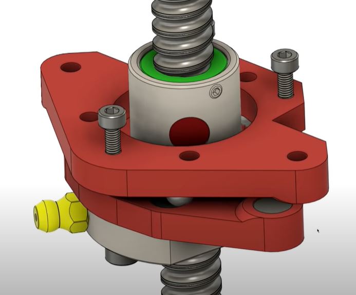
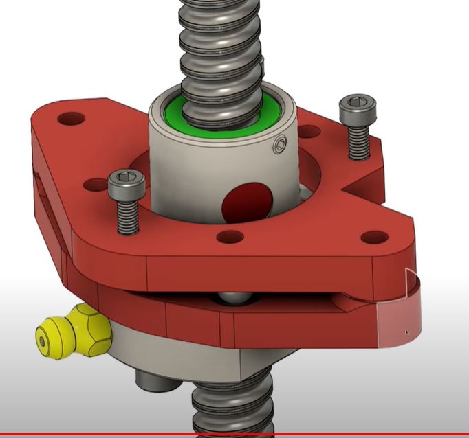
If you look at the category of the rolled ball bearing screws, these take a lot of strain in the material due to the manufacturing process. The strain causes an unequal surface and therefore this can cause lateral wobble. When using these cheap linear ball bearing screws for 3d printers as Z-drives, the lateral problem can be solved by adding shifting plates as horizontal shift compensator.
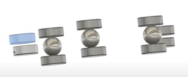
On the net, a solution is given by using a couple of bearing balls (3) between magnets that are used as rolling plates on top and bottom. The shifting plate holders on top and bottom stay aligned with each other by mounting 2 magnets that attract each other on 2 sides of these plates. Please see the cutouts I took from the movie that is provided in the above mentioned link:
This can be implemented in the HevOrt BUT I feel that my Voron2.4 could really benefit also from this solution. Although the Voron is depending on the vertical linear rails for sliding up and down and a belt mechanism is making the motion happen, the mechanism that compensates for any wobble or different sizing of the frame is only a friction plate of (in my case) 2 PETG surfaces that slides on each other, 1 per vertical axle.
So, I will see what I can find or make to get the above anti-lateral wobble solution built and implemented in the Voron 2.4 asap and see what the result will be!
Voron 2.4 Core XY build
My experiences with CoreXY printers are excellent, so I chose a VORON for my home-built COREXY printer with a print size of 300x300x300 mm.
Developed from a large community, the VORON is one of the best and most reliable 3D printers. And this printer just looks really good!
Via AliExpress, Banggood, Reichelt, aluminiumopmaat.nl and plexiglas.nl I ordered all the stuff, according to the bill of materials I could download from the VORON site.
I printed the PETG parts on the Prusa mini at 0.15 fine.
The ABS parts (red and black) were printed on the Twotrees Sapphire plus. It took a lot of ‘tweeking’ before the ABS came out well but in the end I got a nice result!
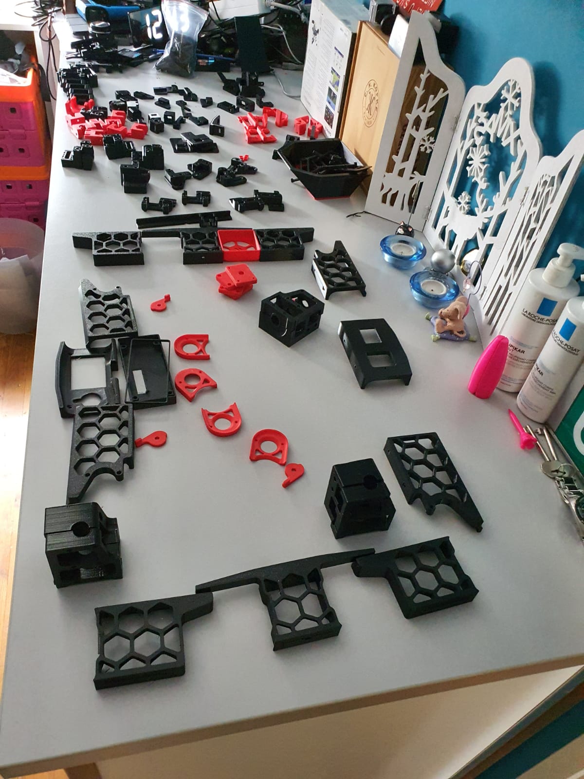
Printed parts for the Voron 2.4 300In the end, rebuilding is not really self-building and it is more based on ordering and assembling than getting to work with the saw and drill yourself. Also the necessary 8(!) linear rails of 350mm, bearings, gears, belts, motors, electronics and so on have been ordered and the rest of the necessary stuff has been printed (25-8-2020).
For the control part I have chosen one PI Raspberry PI 4B 4GB and two pieces of SKR 1.4 turbo motherboards, according to the VORON recommendation.
Building the Voron 2.4 with the afterburner Beta1 hotend combination is illustrated by the following pictures.
Gantry ready:
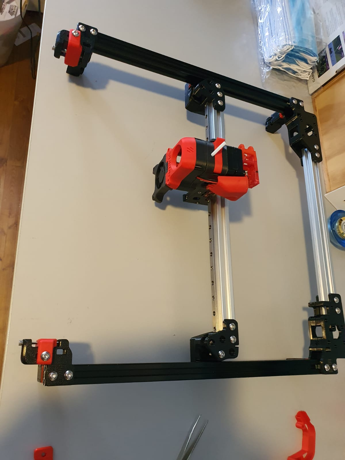
Gantry of my Voron 2.4 300Housing and skirts underside with Z-motors yet without the gantry mounted:
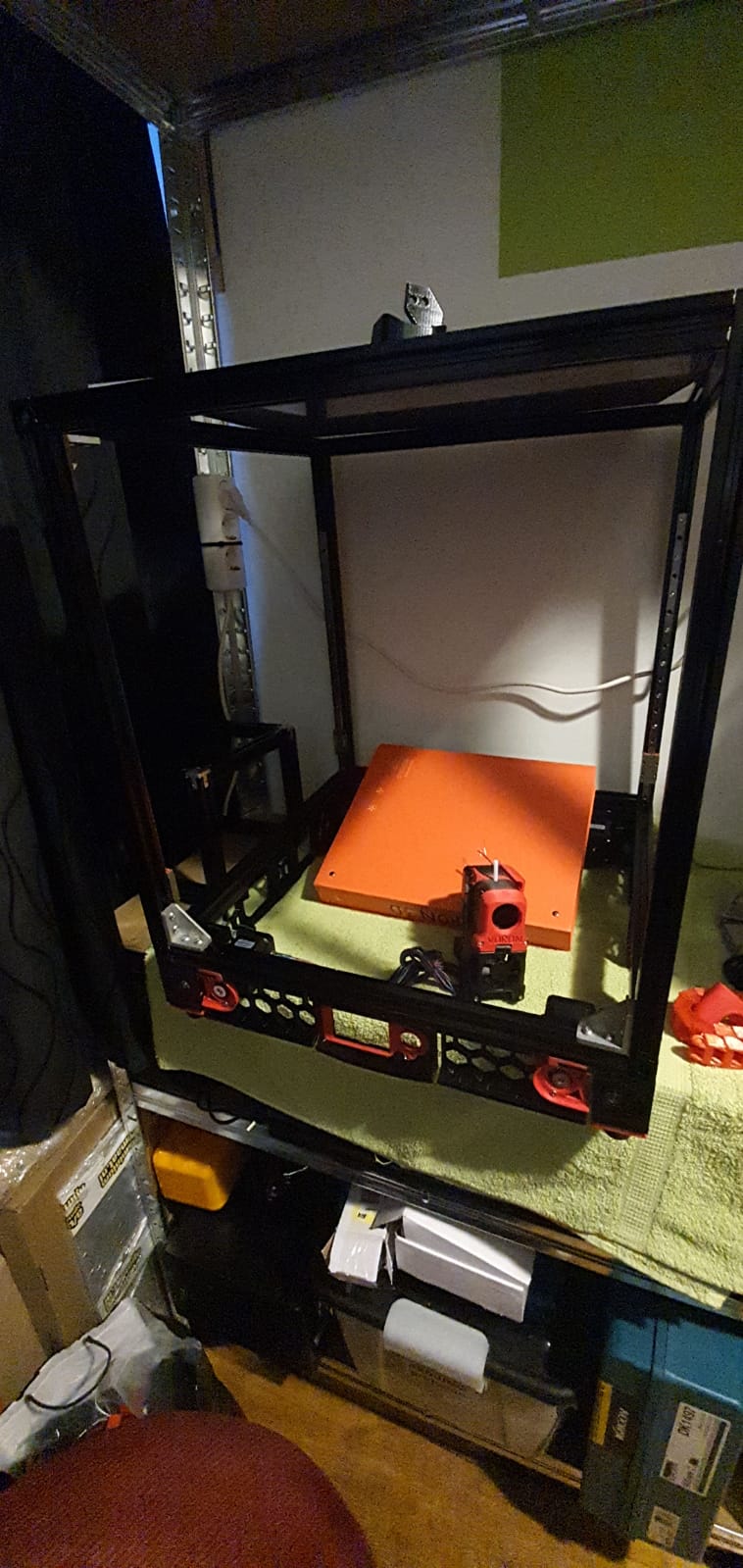
Below: The 9 mm drive belts of the 4 Z-axes placed:
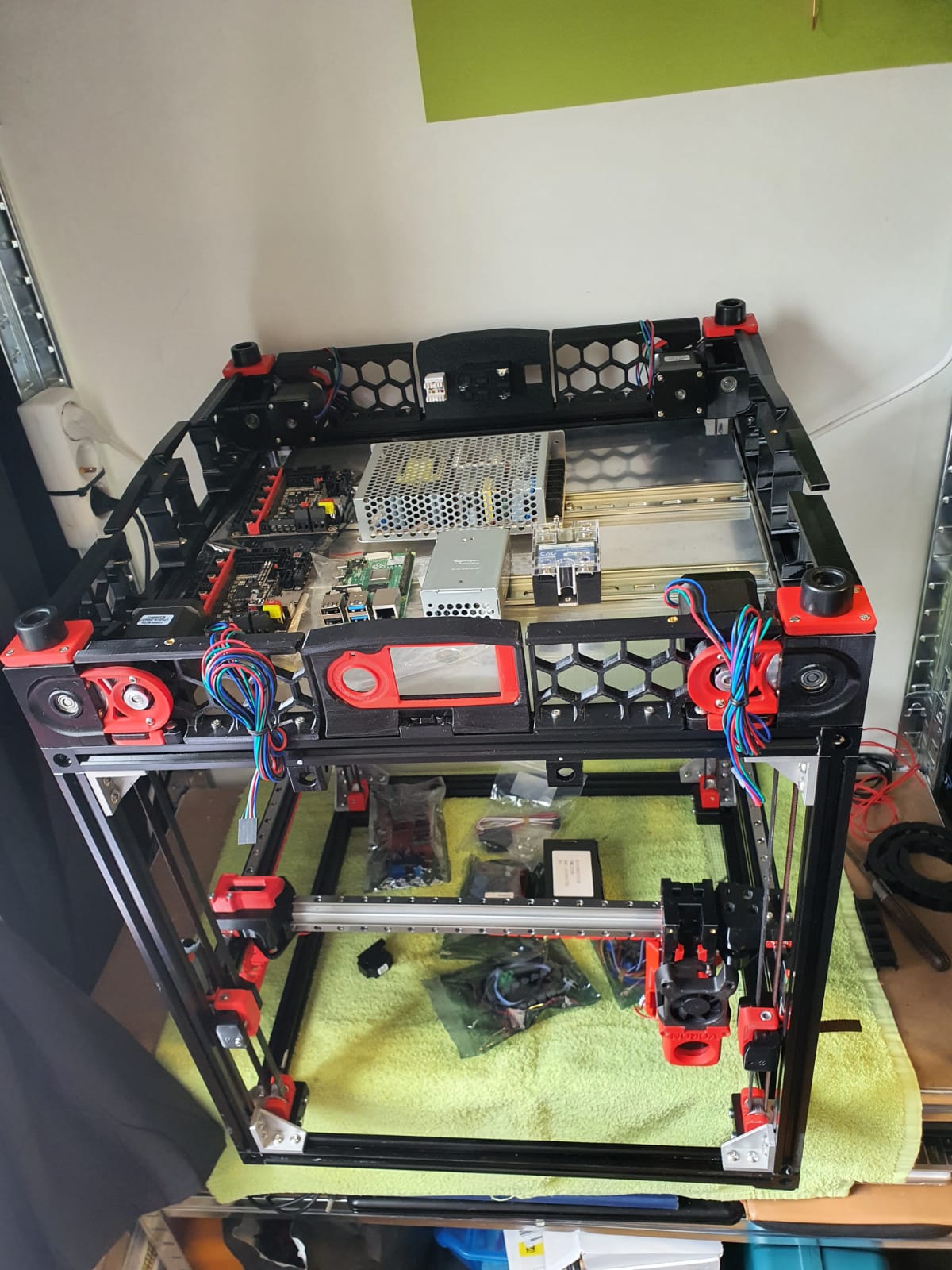
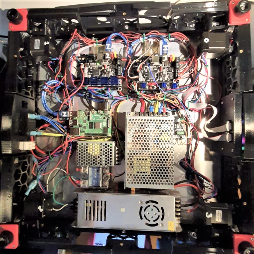
And the assembled base plate with the rails and controls, power supplies and so on (printer turned over):
We are still waiting for the bearings for the Alpha and Beta drives in the gantry. These bearings are used to make a tension roller per 2 pieces. I had originally bought idler bearings for this purpose, but the diameter of the collar of these bearings is just too large.
Too bad but then I have to work on the Raspberry PI4B in combination with 2 times SKR V1.4 turbo motherboards. The PI will make a new config.bin via Klipper for the SKR V1.4 motherboards so the PI can drive both SKR boards at the same time. On the main board will be Alpha and Beta and the extruder plus the extruder heater, on the other (Z) board the 4 Z-motors and bed heater. By itself a Duet with expansion board could have been an option too, but the Voron designers made it with the PI, Klipper and 2 SKR boards. And I try to stay as close to the design as possible . -)
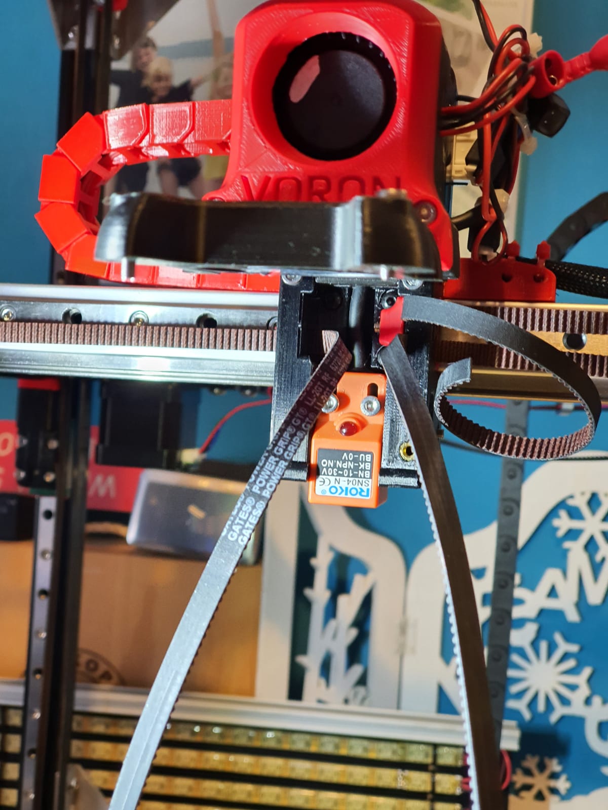
Below: Threading the straps, no picture used. Just start somewhere and you’ll end up right. Oh yes, also changed the sensor in the config from NC to NO..
Below: In addition to the 24Volt 200 Watt hotbed nevertheless also added the 500 Watt 230V. With only the 24V version it took more than 20 minutes to get to 110 degrees Celsius…
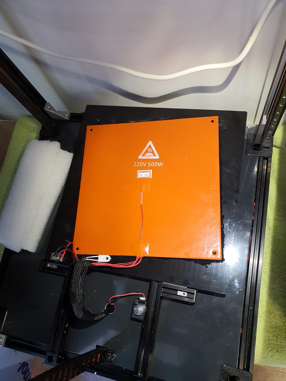
Old:

And new— no PID run done yet..)

Below: The steel plate is placed on the sticky magnet sheet.
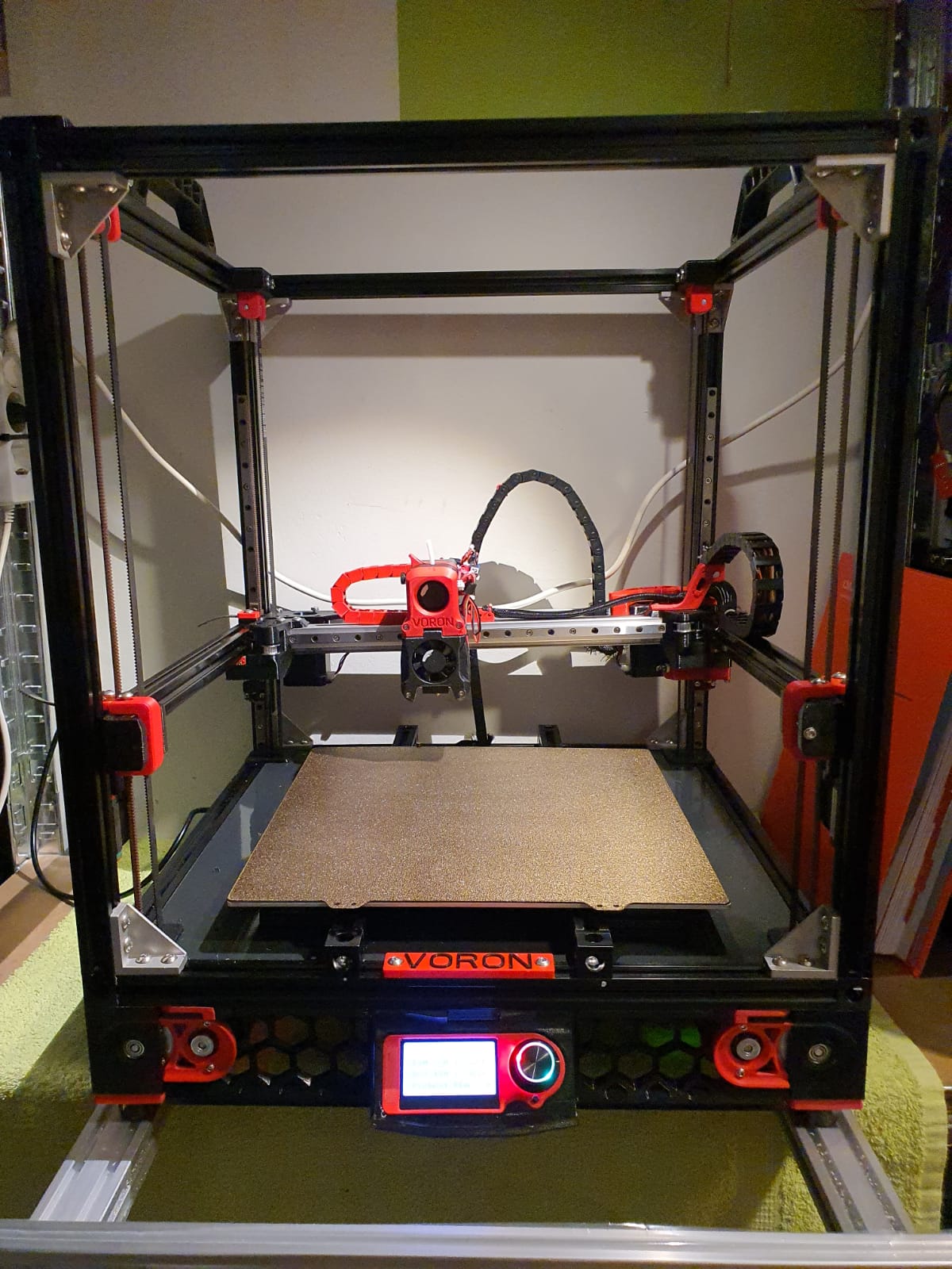
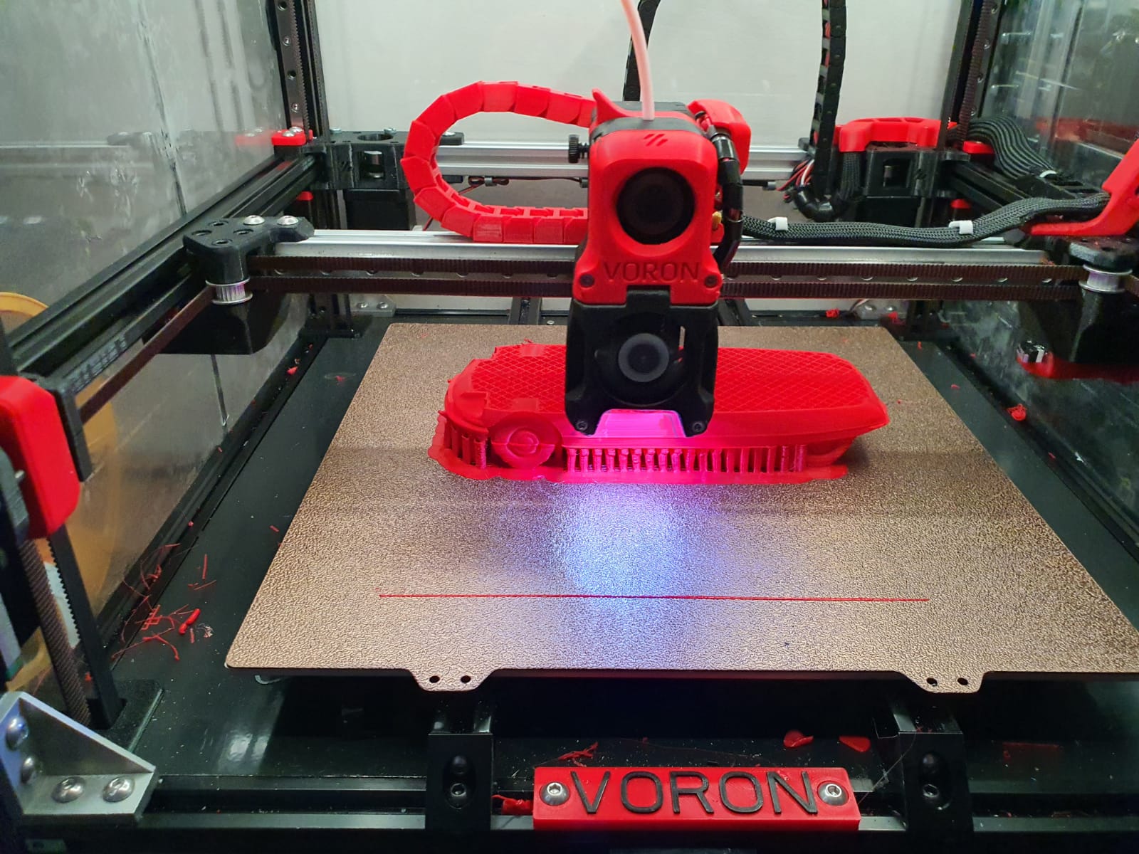
Below: First print…. I had to search for the Z offset adjustment and the extruder turned the wrong way around. Also the gantry leveling took some thought, you actually have to make the basic setting with a ruler, otherwise the leveling takes a long time. Nice is that a bed mesh leveling is not necessary anymore, but of course it can be done. You turn a home and because the nozzle always calibrates the Z on the mechanical Z endstop, and the gantry does all the leveling, you always have a good first layer. Unless the bed warps but with such a thick plate that seems almost impossible. Just to be sure, I did include a bed_mesh profile in the config.g. By the way I just used a 24 V aluminum hotbed as a base because my 8 mm 310×310 plate turned out to be a cut plate instead of sawn. And a cut sheet turns out to be non-flat on the cut sides by default, unfortunately. Flattening costs more than a new plate, maybe that will come sometime….
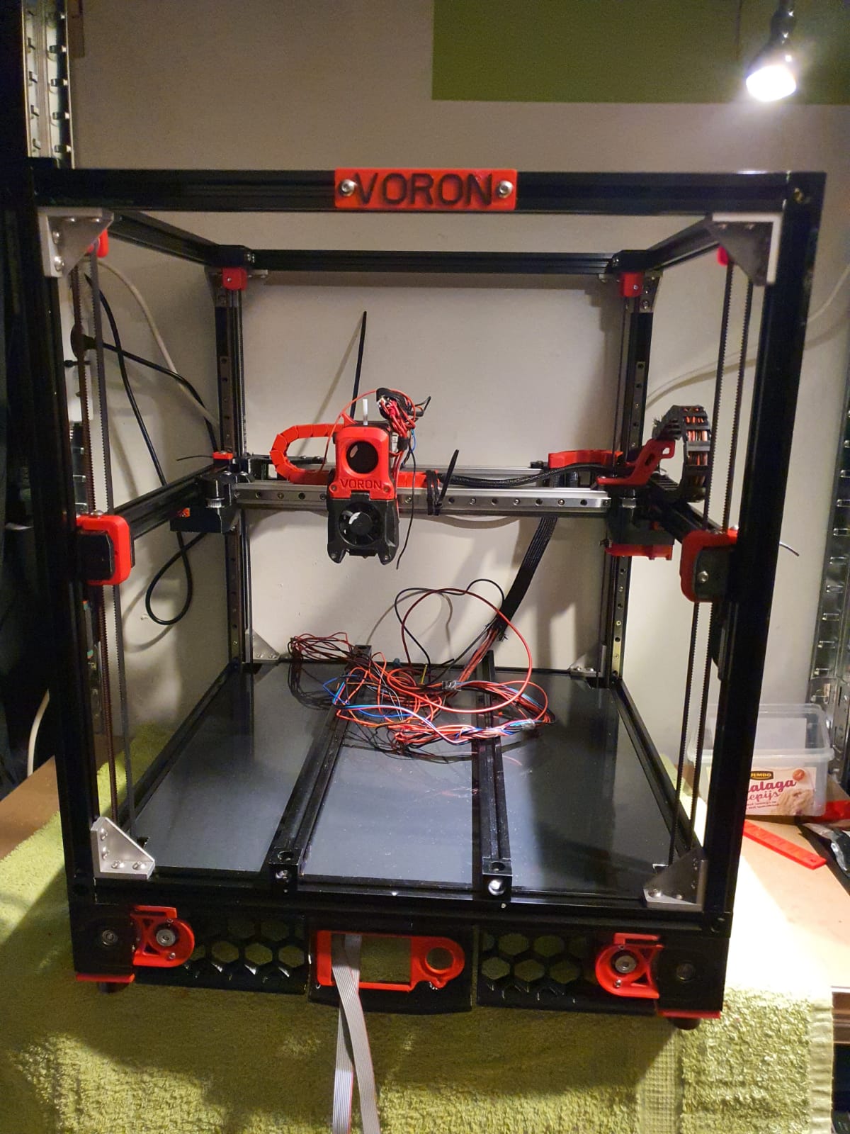
And with enclosure, camera and the TOP LED’s:
Afterword:
In practice, I fixed a few more minor flaws, including:
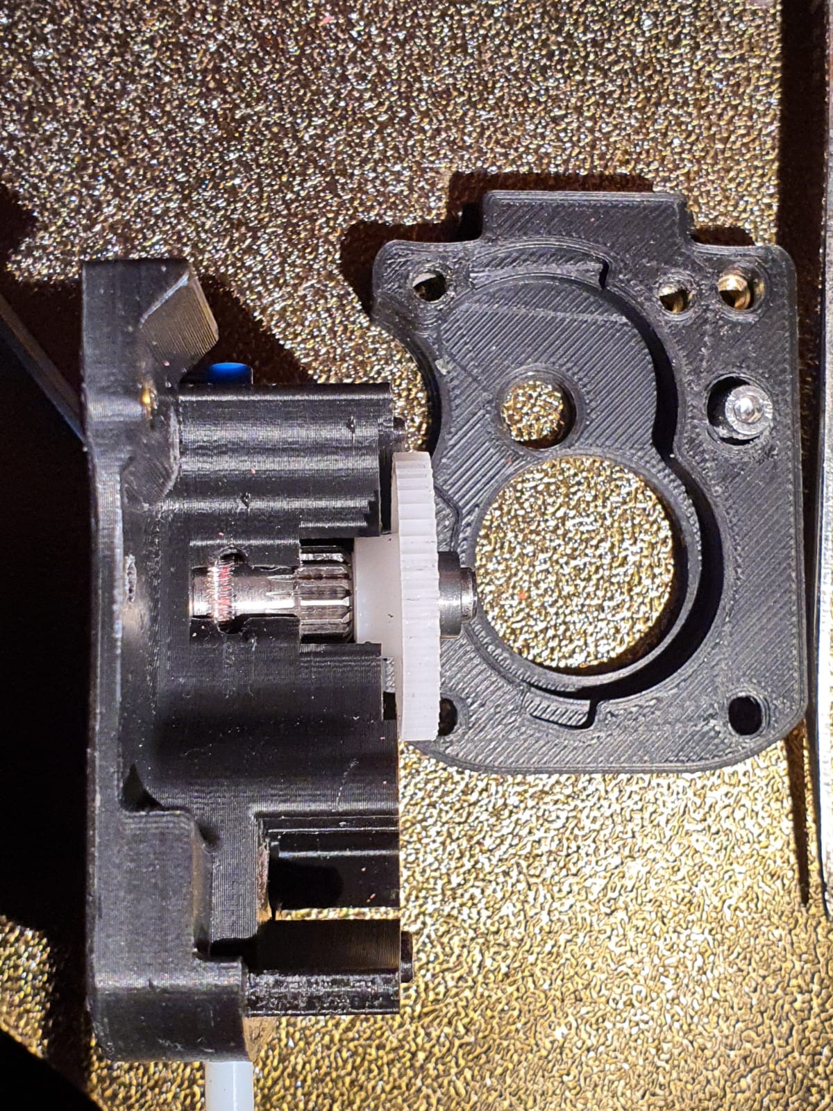
Extruder tuning. The donor extruder turned out not to pick up the filament properly.
First I tried to put a ring in between the left side of the shaft, but then the nylon gear on the right side of the shaft gets tight and the housing can’t be closed completely anymore….
I ended up using a spare set of dual drive extruder gears and swapping the set of gears. With that, the filament was properly aligned with the running path of the gears. See the picture how it was at first:
Hotend tuning
After the PID runs of hotend and heated bed, my chosen assembly of the custom ED6 heater block, the heatbreak pipe and the cooling element turned out not to fit together properly. The result was that when the filament was extracted, a thick piece was always stuck at the end. This was caused by the heatbreak pipe not fitting tightly on the nozzle. There should be no play between them. I completely demounted the filament and screwed the heatbreak pipe 2 turns less into the cooling element with red threadlocker. Let it harden for a day and then I assembled the rest. By the way, I also mounted the teflon version of the heatbreak pipe in stead of the titanium version. The tintanium version was to my experience a bit too stiff. Or my filament was too old or inferior. In any case, after the modification, everything works without problems.
Hotbed, TPU and ABS
To print TPU and ABS without brim or skirt without warping I bought a magnetic PEI steel plate with coarse profile. It really works perfectly. Both ABS at 110 degrees sticks nicely and TPU at room temperature sticks nicely too. And the removal is also without problems. Occasionally I spray a little hairspray on the plate but I don’t think that lacquer is really necessary at all. It is meant to make the removal easier.
Tension of the belts
I tried getting the belts at the same tension, this was not that easy. Finally I ended up with a mechanical way of measuring tension after putting 1 at my desired tension and comparing this as reference with the other to be compared belts. So, for the Alpha and Beta belts I first did a ‘good feeling’ setting and then I used my old trunk scale weight device to measure the tension when pulling the belt A. Then, I used the device to measure at the same place for B. And I repeated this for the 4 vertical belts.
Alignment
Aligning the machine is also a bit of a challenge…
You must assume that your frame is square and straight. You have to check this thoroughly. Both vertically, horizontally and diagonally. Then you can adjust the gantry. Loosen and remove the A and B belts. Or do the alignment BEFORE placing the belts.
Fix the horizontal position of the Gantry otherwise you can’t align at all. Place 4 equal distance blocks of about 10-15 cm under the sliders of the vertical linear rails on the lower 2020 profiles, in the 4 corners through which the gantry rests stably. I have placed position holders under all MGN9 vertical linear rails afterwards so that the rails cannot slide in the 20×20 V profile. If you use ‘regular’ 20×20 extrusion profile you don’t have a problem because there is enough ‘meat’ left for attaching your rail to the profile. With V-profile, the groove is a bit wider and it is very difficult to mount the rails neatly without tools in the groove. My frame is of V-rail profile and the gantry of plain 2020 profile.
The alignment of the gantry I started at the back. Loosening all screws a bit, including the screws of the convex connectors that hold the gantry to the linear rails. By the way, I see some builders placing these screws with multiple spring washers. I’m going to do that too…
At the rear of the gantry, push the gantry completely against the rear. There should be no gap between the XY joints and the frame. PS: Leave the endstops off for a while at this action!
While the gantry is sitting against the back, tighten the XY joints and the sliders of the X-axle as well. (the side of the endstops holder is temporarily secured with 2 screws)
Tighten the rear 2 gantry joints (with the convex surfaces) as well. This fixes the rear position at right angles.
Carefully slide the gantry forward. This should be possible without any effort. If not, check whether there is enough play (and if necessary loosen the screws) on the gantry joints at the front (with the convex surfaces). If you still don’t have a free run to the front, your frame is not good or your vertical rails are not seated properly. First check the correct positioning of your rails with your position tool (from the printed stock) and to be sure also unscrew the 4 screws on both front vertical rails. Try again if the sliding of the gantry goes smoothly. Still no good? Then reverse the procedure and start at the front. Try to set the gantry exactly level with the frame.
After adjusting: Test the alignment also halfway (vertically) and at the top!
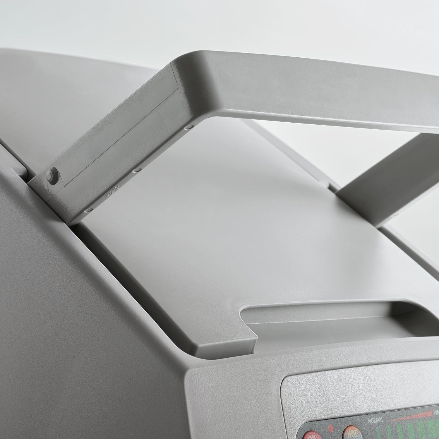
Geetech A30M first use
In mid-June 2020, I started using the Geeetech A30M desktop 3d printer.
The printer can print 2 colors mixed with 2 filament geared drive units on top of the frame and a fan for each feed to the combined hotend.
A few adjustments are needed on this printer if you really want to work well with it.
First of all, I had a lot of trouble with the standard noise from the 24 Volts fan under the bottom plate, which is supposed to provide cooling for the motherboard. This fan is always running at full power.
I put a controller in between with controls on the left side, through a drilled hole. I secured the controller with 2 tie-wraps through the cooling slots on the left side. The dial just comes through the case and you can hardly see it. Most motherboards I use don’t need a fan for cooling because they are placed freely in the open frame but the A30M has a closed case so a little air circulation is necessary. Plan is to add a thermostat control so the knob is no longer needed. Later. The controller is set to the position that there is a lot of air movement but without the whirring of the fan.


Second modification is the addition of a Geeetech 3d touch on the hotend. The bracket was included with the printer, suitable for both a thick inductive sensor and the 3d touch sensor. What’s nice is that the software (or firmware, if you will) as suitable from the factory for autoleveling. Do pay attention to the correct placement of the connectors, from the front view the brown and black wires should be mounted to the right.
The disadvantage is that the firmware from factory does not really work well with auto leveling. In the middle of the hotbed everything goes fine but with larger prints I noticed that the first layer was printed very differently, so everything kept coming loose. So now I work with manual leveling while automatic leveling is possible.

The hotbed is nice and big with a workable size of 320x320mm. The print height is 420mm.
The price was over 400 Euro, and the delivery was from Germany.
I recommend everyone to secure ALL and especially to include the block hook. My one was really not assembled properly. All threads were OK but all bolts were either too tight or not tight at all. I only found this out during the first test print. I stopped and checked everything. Pay special attention to the rollers of the hotbed. It is difficult to reach them but in my case the adjustment wheels were not set at all and did not rotate. The disadvantage of such a desktop printer is that you hardly have any space under the hotbed.
The vertical V-profiles were not mounted perpendicular to the upper profile. That is difficult to repair because everything is drilled through and bolted. I recommend installing corner stiffeners at the back in the top 2 corners. I have them on order and then they can go right on.
And… what some large printers have and the A30M does not: Additional stabilization rods to the front (or to the back, that is also possible) so that the vertical profiles cannot move. Now when you apply a little force there is about 2mm of play on it, despite the solid mounting to the desktop housing.
CNC pendant for Duet2wifi and Indymill
On the Duet support site a very good description and software for rebuilding a Chinese CNC-pendant for the Duet2wifi is available.
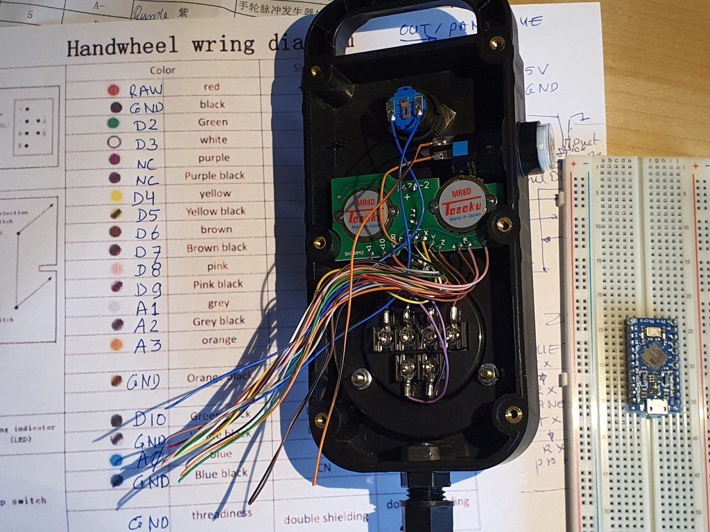
I used this description to program an arduino pro micro, and connect it to the pendant wired, place it inside the pendant and connected the pendant with 4 wires to the Duet. This works very well.
In the process, I developed some schematics that may be useful to you, available in this post:
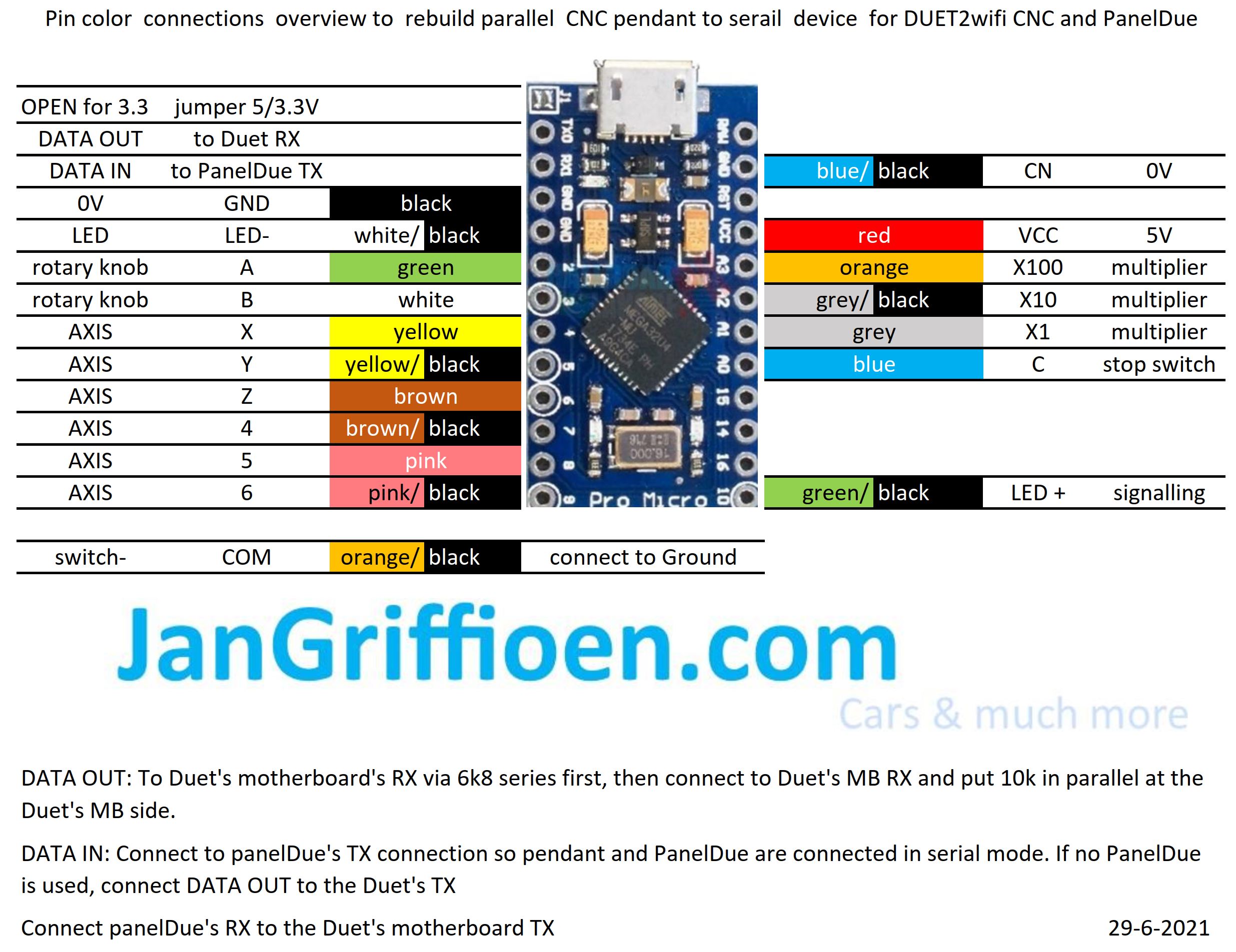
Needed: an arduino pro micro and a pendant like this:

Original ID 1965 leather front chairs for my Citroën ID20 convertible (1970)
2021-June 6th.
Original ID20 chairs for the convertible are very hard to find, especially lately.
Fortunately, I have a complete set on stock with the front chairs side handle to fold the back forward, both left and right in the original brown leather version.
Also, I have the rear bench and back from the same donor ID (1965). The rear bench don’t fit in my 1970 ID20 convertible but the front chairs will fit nicely. I will get the car tomorrow out of the winter storage and will put the chairs in this week. Then, finally, I can take the temporary Volvo C70 chairs out.
I will post some pictures to show what this looks like, asap!
Dometic tropicool TC21FL silenced
Recently I bought us a portable dual power cooler from Tropicool, 21 liters content. BUT- as I started it up, the noise was a bit more than I expected.
I already own a larger ‘VRIJBUITER’ 38 liters portable freezer/cooler with a compressor that I silenced last year.
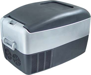
This 40 liter machine had a 50mm (2 inch) fan to cool the condensor and I completely repositioned some movable parts to get a 120mm (4.8 inch) fan in the machine instead. The 120 mm fan is a silent fan and this resulted in an almost silent and better operating freezer/cooler. But- this machine does not run on the car battery, only on A/C 230 Volts.
So- back to the Dometic machine: This is the machine
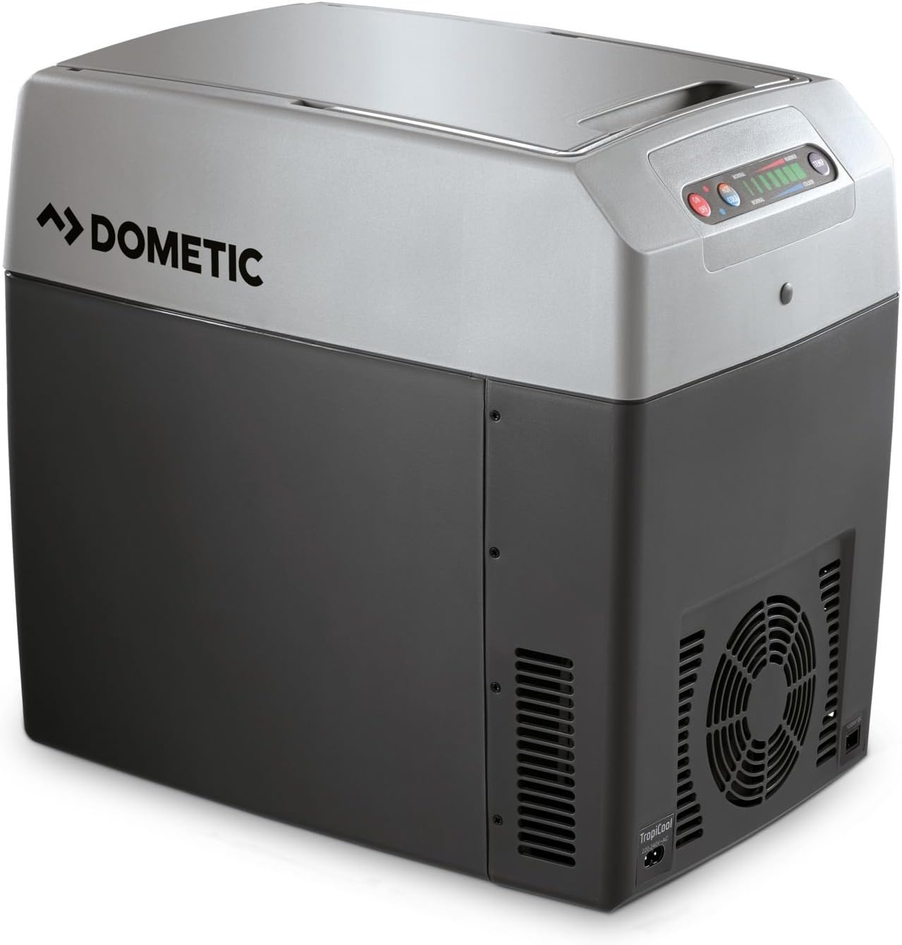
At the front lower part a large area shows a fan behind the plastic front. A 12 Volts DC fan is positioned behind this front . The fan is managed by the electronics and only switches on and off. No PWM or similar technique is used. This cooler is not working with a compressor but with a/some Peltier element(s) and cooling/heating radiators, so a big aluminium block needs to be cooled by the fan to get the machine to work (and cool or warm the inside). This machine can either cool -25Deg C or warm +25Deg C the inside. A failsafe mechanism prevents freezing and temperatures above 65 DegC.
The picture below shows the original fan below and the replacement fan above.
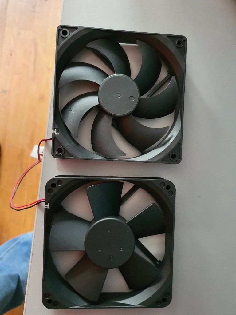
The original fan was IMHO rather loud at 53 dBm (at 50cm distance), I presume mainly due to its design.
On the net, I read that most users of this machine are pleased with it and don’t think it makes much noise.
But- I need to operate this in our rented place which can either be an apartment, B&B or hotel room during our visits so I want it to make as little noise as possible. The replacement fan is a ball-bearing super-silent PC fan and runs at 12 Volts.
The replacement was quite easy: Open the lower front by removing all crews around and bottom. Disconnect the fan-connector from the electronics board. Unscrew the old fan. Screw the new fan in place. Connect the new fan to the electronics board, replace the housing part and screw it back in place.
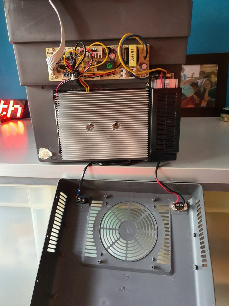
So- the result is that this cooler now actually works a lot more silent, AND a lot better.
I could not get a fixed dBm reading with my portable dB-meter due to the low noise level.
Cooling goes faster than before at about 30% as I measured it in difference in the before- and after situation in cooling to 5 degrees C from room temp of 25 deg C. Another succesfull project!
We’ll see how we like this cooler during our short stay in France this summer, in Granville! C) JG 2021-06-30.
Afterthoughts: To be sure that the cooler is indeed super silent at night, I also put in a DC voltage regulator that can regulate the voltage for the fan between 5 V DC and V max (about 12Volt).
During oiur holiday in France, the machine worked awesome.
In the hotel, we experienced no disturbances from the cooler at all, nore in the car.
And it kept everyrhing cool without too much noise.
FLY 407 Motherboard RRF3+ wifi + BTT 2.4 inch TFT + multi-extruder
2021-05-11
I got the Mellow Fly 407 board in today, and it now works awesome!
I hooked the Mellow dedicated wifi unit to EXP 1 and EXP2 and to the serial TFT connection, programmed the microSDcard offline on the PC with the files from the proposed Github site and it all went great! (The little added user manual is very good, just follow the directions and it can’t go wrong!)
Burnt the board’s firmware first, then the firmware of the wifi esp module and after setting up the wifi with YAT via USB, I programmed the wifi settings. Then, with the Duet’s WDC PC-remote console via wifi, I uploaded the FLY 407 motherboard with all the latest available firmware: RRF3.4 beta and the latest wifi- and DWC versions.
Then, I removed the serial connection between the TFT connection on the motherboard and the wifi module and plugged in the BTT 2.4 inch TFT at the same serial port. Since there is only 1 tft port available, I use the same serial port as I used for programming the esp wifi module. I already put the RRF3 firmware on the TFT unit.
Well, the results are awesome! On the TFT after connecting you see the extruder step from 0 to 1-2-3-4 and back to 0 so this all works very nice!
I must be honest here: I also tried the Mellow 7 inch screen but this is not yet really working as well to me as the little BTT screen IMHO. The Fly screen is a lot bigger, though, and the Fly 7 inch TFT has great potential. I know that it will also take some getting used to the FLY’s TFT screen layouts. The access to the macro and gcode directory is nice, but since everything is placed differently than the PanelDue screens, it might just take some time to appreciate it more.
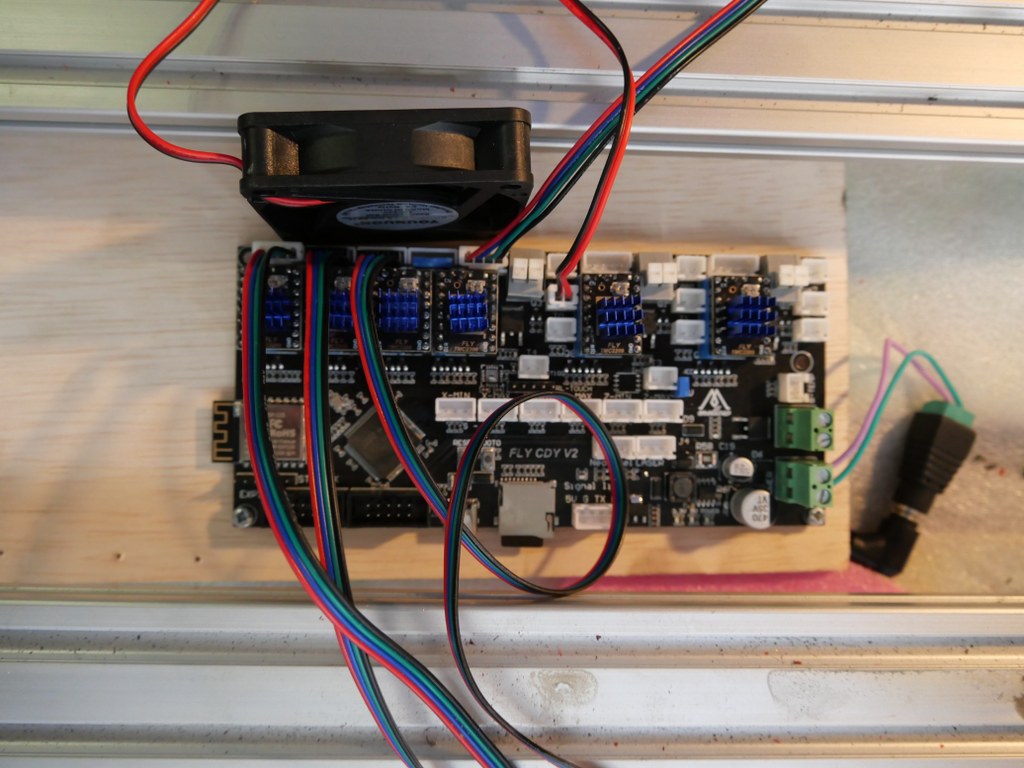
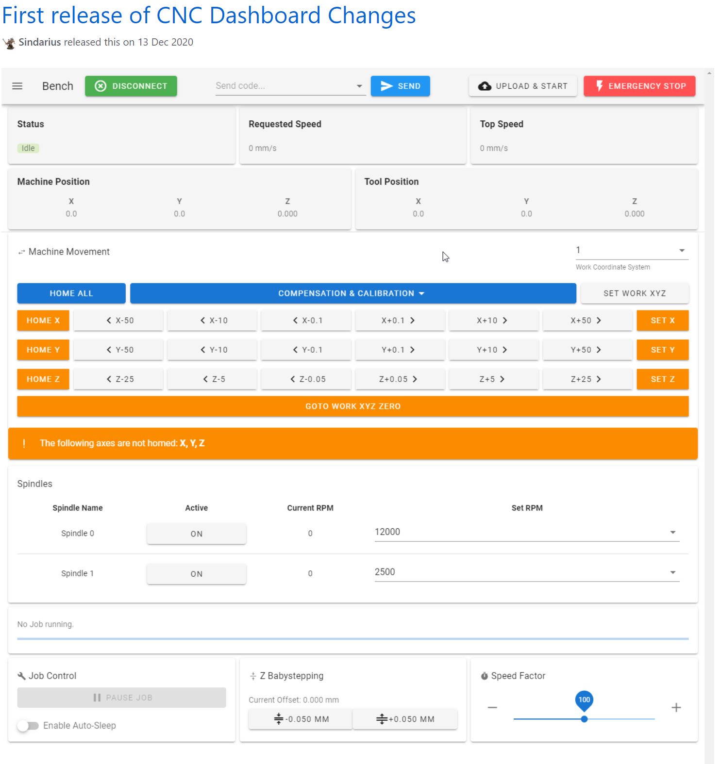
Reprap CNC with Mellow FLY-CDY-V2 – Duet2wifi clone
To get the Indymill running, at first I chose to use the Duet2wifi and reprap3 as base.
Since I am very familiar with Reprap and with the Duet, I want to try this anyway.
In the end, if it is all installed I need to have software to design and get a file with Gcode and this will be sent to the Duet2wifi controller via wifi, using the Duet’s webinterface that is been developed for CNC in Beta (DWC for CNC).
I currently use Openscad for designing, export as .STL and then make a .nc file for the CNC machine from this with Estlcam.
In Estlcam you can make the machine-specific settings like where the center is, how to set Z=0 et cetera.
The Duet2wifi is my favourite solution because I can if so desired use sensorless homing on any axis. And- because I need to home 2 independant Y axis and I have a lot of experience in making this work I first went for this solution. For my settings with sensorless homing please see THIS POST
When you get a good enclosure for the Duet2wifi, use 24 Volt PSU and good driver cooling blocks, you can push the Amps to over 2 Amp continuously. Works well with my Nema23 steppers. 2.5 Amps is max but we don’t want that, I found that 1.8 Amps works very well and creates enough torque for the Indymill.
After having the Indymill work with sensorless homing I rebuilt all to be used with endstops instead for better stability and compatibility with my other driver board setups. I do want to use the Indymill with several driver setups, and for this setup to be exchangeable, I need the endstops anyhow.
I am currently using reprap boards from Mellow, since they use the raprap firmware that is ported to the STM core that the Mellow boards use.
On top of this, on the esp you can mount the Duet’s DWC software and thus also the DWC CNC software.
I have this currently running on the Indymill with a FLY-CDY V2 board and TMC2209 drivers.
The nice thing about these Chinese boards is, that you can mount any driver you like, and this means that external drivers is also possible.
So, also the external add-on drivers that do closed loop control can be used. < I was thinking to make this my additional project: Try to do sensorless homing on the Y axes with this, use very low power and switch off the Closed loop during homing.. If I can get this to work, you will read all about it!>
For the Duet, a setup is available on the Duet website to use an original pendant handwheel unit and add an arduino Pro micro to make a serial interface for connecting to the Duet! That is a very welcome addition. See this post!
In the next part of this post my current config file with endstops for Duet/reprap/FLY is shown, as this is operaional for the Indymill.
BE AWARE to use the most current DEVELOPMENT firmware versions for a) the board’s initial firmware, b) the DWC firmware and c) the wifi esp program!
; Configuration file for Board: fly_cdyv2 (STMWiFi)
; Firmware: RepRapFirmware for STM32F4 based Boards 3.3beta1_3 (2021-03-08)
; Duet WiFi Server Version: 1.25-01S-D
; DWC from Sidarius, specificlly redesigned for use with CNC 3-axis
; customized by Jan Griffioen sales@jmwg.nl 2021 04 08
; Made for a CNC Cartesian printer with single X,double Y and single Z steppers and a single spindle with external driver.
; General preferences —————————————————————————————————————-
M453 ; CNC Mode
G90 ; send absolute coordinates
M83 ; and relative extruder moves
M550 PDUET_CNC ; set printer name
M551 Preprap ; Machine password
M552 S1 ; WIFI ON
; Network —————————————————————————————————————————-
M586 P0 S1 ; enable HTTP
M586 P1 S0 ; disable FTP
M586 P2 S0 ; disable Telnet
M552 P0.0.0.0 ; IP address (0.0.0.0 = use DHCP)
M554 P192.168.178.1 ; Gateway
M553 P255.255.255.0 ; Netmask
M555 P2 ; Set output to look like Marlin
M575 P1 S1 B57600 ; comms settings S1 for Original PanelDue and Fysetc 7 inch TFT =OK
; Drives —————————————————————————————————————————-
M569 P0 S1 D2 ; physical drive 0 goes forwards using default driver timings
M569 P1 S1 D2 ; physical drive 1 goes forwards using default driver timings
M569 P2 S1 D2 ; physical drive 2 goes forwards using default driver timings
M569 P3 S1 D2 ; physical drive 3 goes forwards using default driver timings
M584 X0 Y1:2 Z3 ; set drive mapping
M350 X16 Y16:16 Z16 I1 ; configure microstepping with interpolation
M92 X640 Y640:640 Z1600 ; set steps per mm
M566 X500 Y500 Z300 ; Set maximum instantaneous speed changes (mm/min)
M203 X2700 Y1400 Z1000 ; Set maximum speeds (mm/min)
M201 X300 Y300 Z150 ; Set accelerations (mm/s^2)
M906 X1800 Y1800 Z1800 I30 ; set motor currents (mA) and motor idle factor in per cent
M84 S100 ; Set idle timeout
; Axis Limits ————————————————————————————————————————-
M208 X0 Y0 Z0 S1 ; set axis minima
M208 X500 Y480 Z100 S0 ; set axis maxima
; Endstops —————————————————————————————————————————-
M574 X1 S1 P”^xmin” ; configure active-high endstop for low end = LEFT on X via pin xmin
M574 Y1 S1 P”^ymin+^ymax” ; configure active-high endstop for low end = REAR on Y1 and Y2 via pin ymin and ymax
M574 Z2 S1 P”^zmax” ; configure active-high endstop for high end = TOP on Z via pin zmax
; Z-Probe ——————————————————————————————————————————
; a probe must be defined here to have a Z=0 DATUM, including the offset (when there is any, If you use the tip of the tool no offset is required. OR, use manual Z-datum setting via a dedicated macro!
; Mesh G29 —————————————————————————————————————-
;M557 X15:215 Y15:195 S20 ; define mesh grid to be called upon by G29 for an authentic Mesh bed levelling IF this is required and possible
; Fans ———————————————————————————————————————————–
M950 F0 C”fan0″ Q500 ; create fan 0 on pin fan0 and set its frequency
M106 P0 S0.5 H-1 ; set fan 0 value. Thermostatic control is turned off
; Tool definition section; —————————————————————————————————————-
M950 R0 C”!e2heat” L25000 ; Create spindle index 0, with PWM pin on heater 2 output and 25000 RPM achieved at full PWM. At this port, add a PWM-> Voltage 1-10V converter!
M563 P1 S”Spindle 1″ R0 ; Create tool 1 with spindle 0 and call it “Spindle 1”
; Miscellaneous —————————————————————————————————————————-
M140 H-1 ; Disable heated bed
M564 S1 H1 ; Disable jog commands when not homed
M98 P”customconfig.g” ; Execute custom config settings
; Epilogue ———————————————————————————————————————————
;M556 S78 X0 Y0 Z0 ; Axis compensation here if needed
;m98 P/sys/leds_show.g ; Neopixels show (max number is 60)
;m98 P/sys/leds_off.g ; Neopixels OFF (max number is 60)
T0 : select first Tool
M501 ; execute config_override.g
Indymill increased working space and stability Y-axis
2021 05 13: Yesterday I received the iron plates for my Indymill from Nikodem Bartnik, and it was all very well packed and quickly delivered!
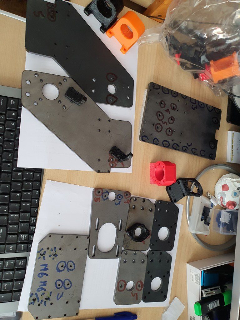
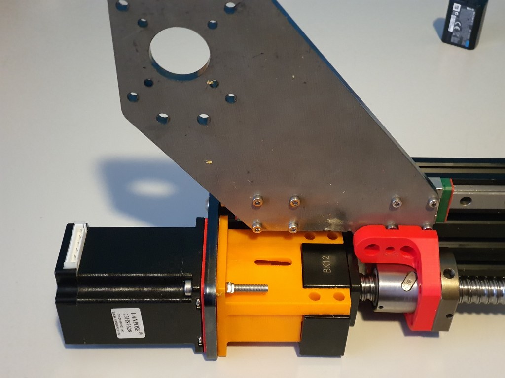
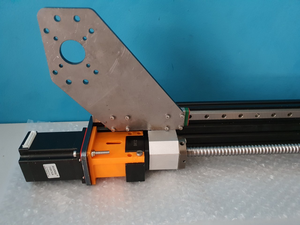
As I always do on any build, I first check the separated axis for best fit and possible improvements. I started with the Y-axis. In the below picture, the left side of the macine is shown, being the left Y-axis. The rest of the machine is not yet attached.
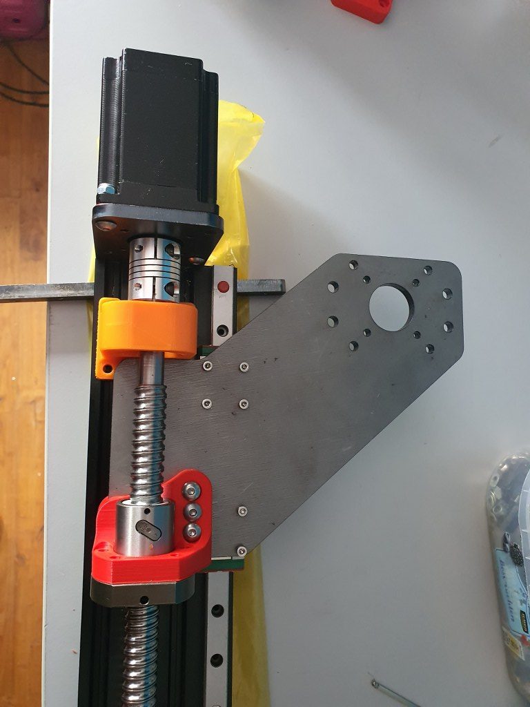
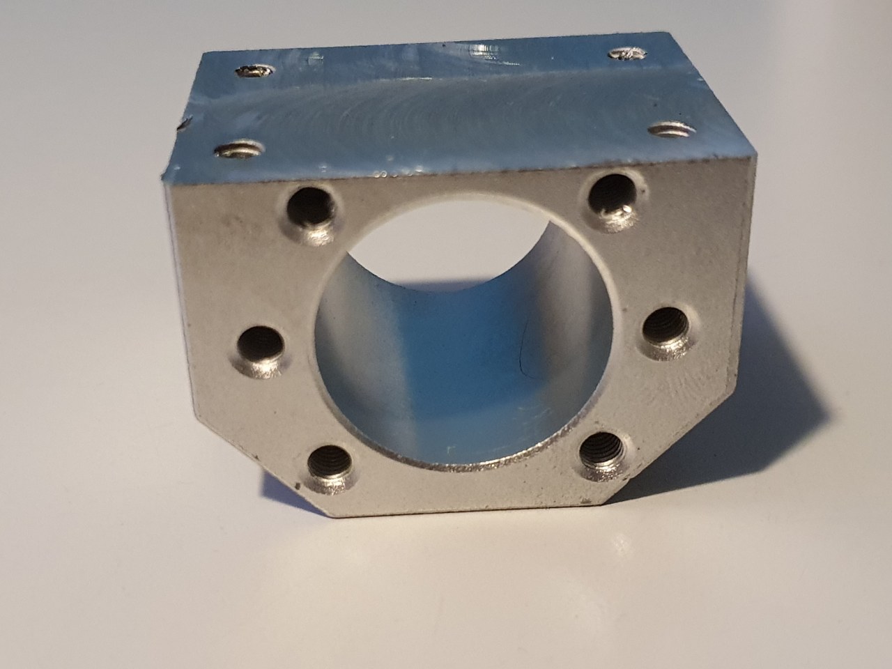
The Y-axis is somewhat limited in its drive towards the rear of the Indymill CNC machine, due to the bridge plate for the X-axis. This bridge plate is blocked in its movement towards the rear because it hits the bearing block (orange part) that holds the ballscrew in place. By removing a small and unused part of the bridge plate, the movement can get about 6 cm extended towards the rear. The pictures are attached to this post, please see how I made this.
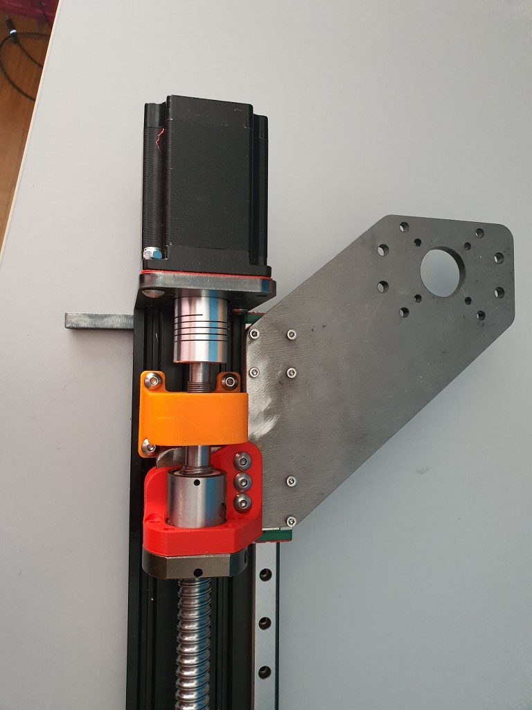
I used the plasma cutter to cut the parts out of the 6mm steel plates and after this was done, I used the lamel grinder to make it smooth. Although I used a guiding rail for cutting, the power was apparantly a bit too much so it is not a very beautiful cut… -) No worries because all still fits very well.