I bought a couple of BIQU H2 extruders to experiment with them.
The first printer I chose to mount this extruder is my TT Saphire pro.
I own this printer for a couple of years, and it behaves quite well. But the original bowden setup is not my preferred setup, and the BIQUH2 seems very promising.
On the net, I found a 3d printable bracket with a seperate mount to re-use the 2 small 40mm side tool fans again as tool fans.
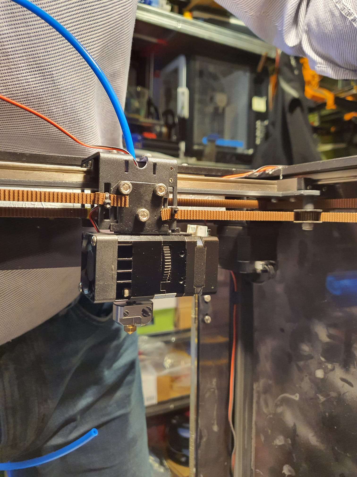
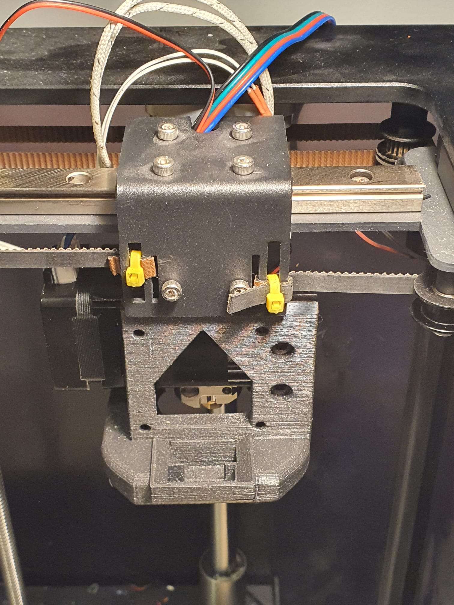
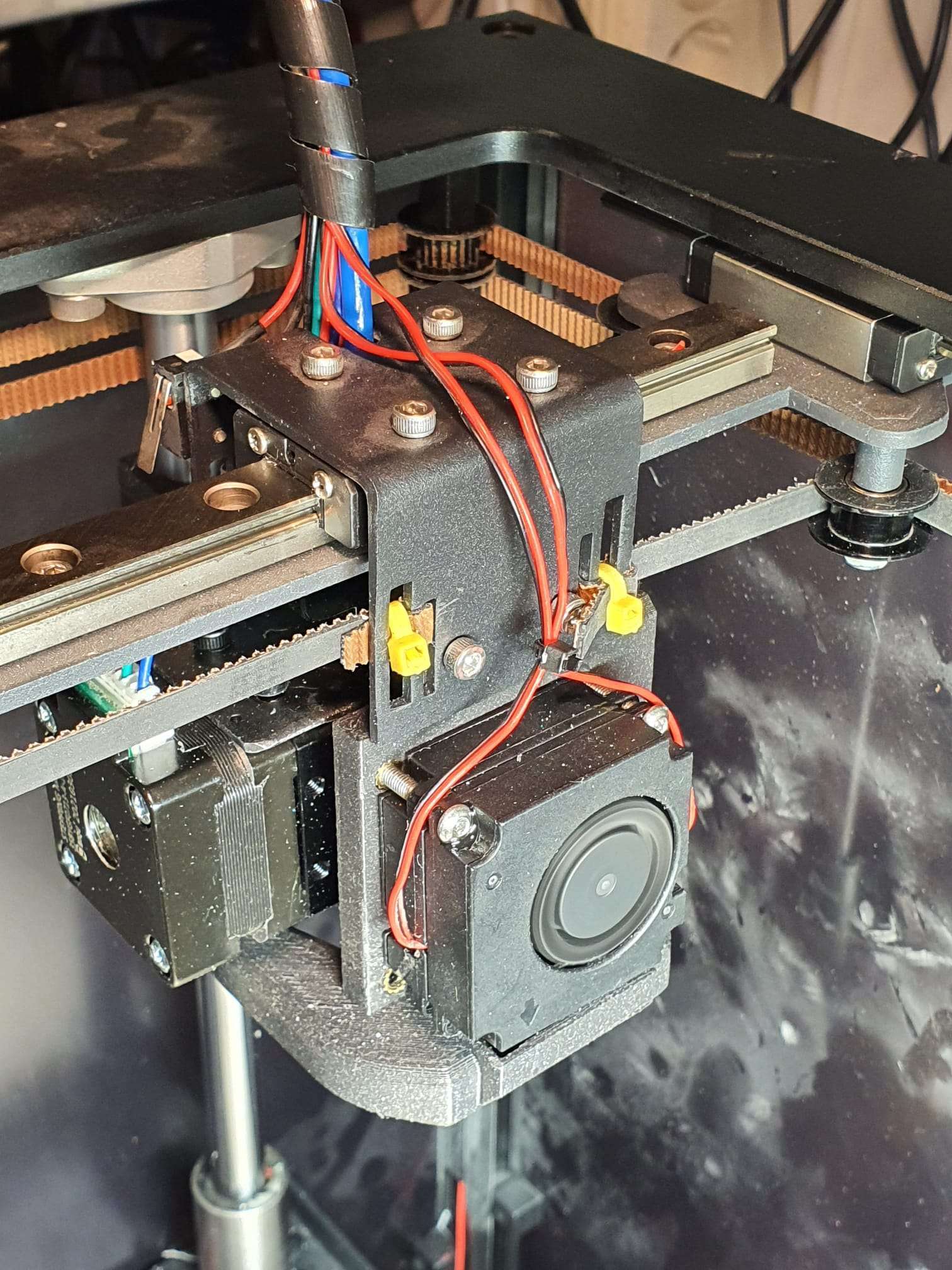
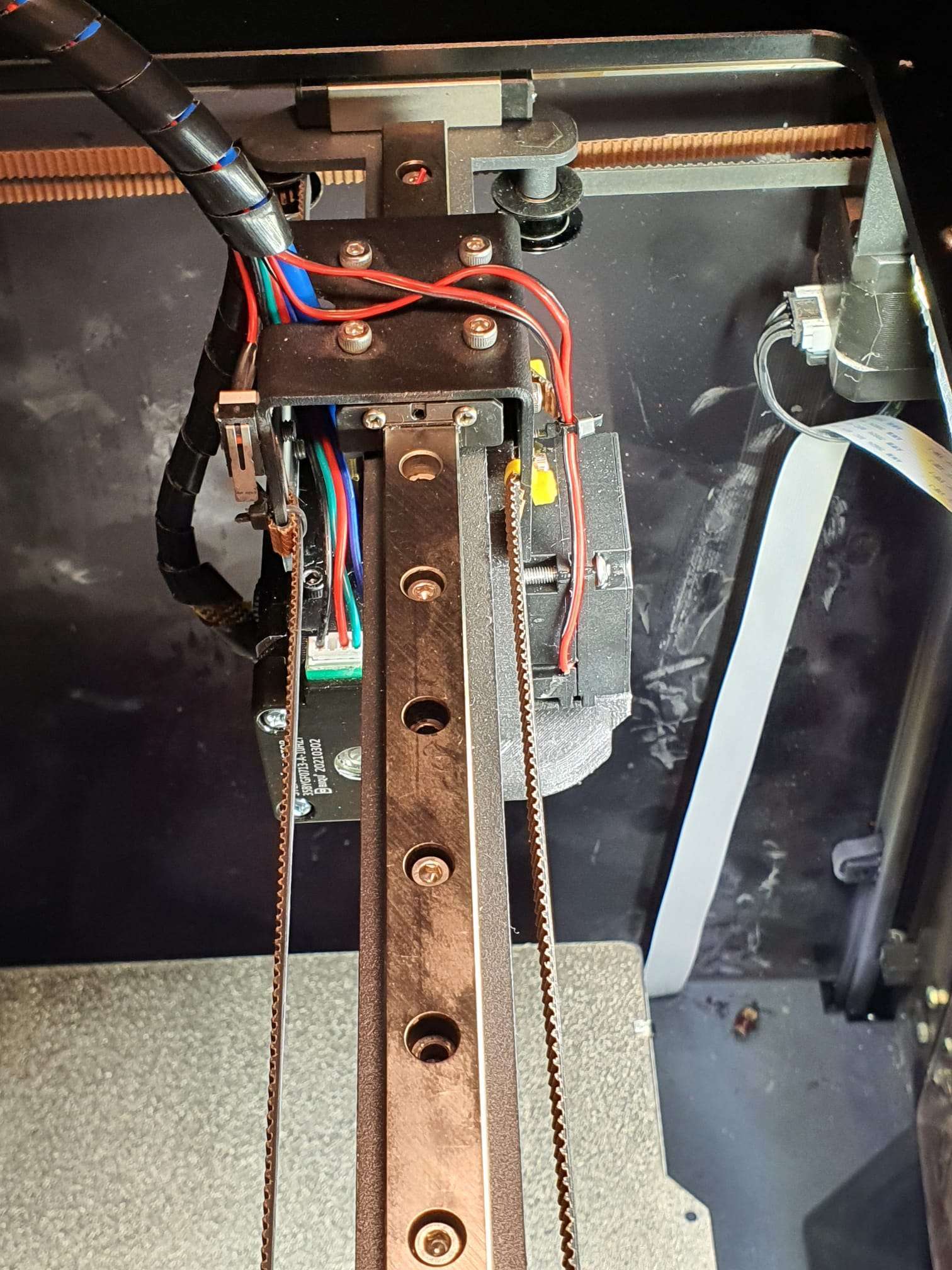
I ditched the 3d printed mount for the extruder and made me e steel one, from the old hotend mount. That is what the pictures in this article will show.
The 3d printed toolfan mount is a bit modded because I have reversed the entire setup, so I will keep within the original specs of 235x235x200 mm printeble size.
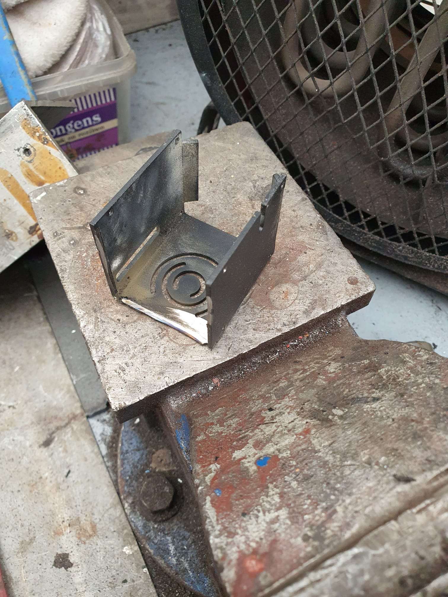
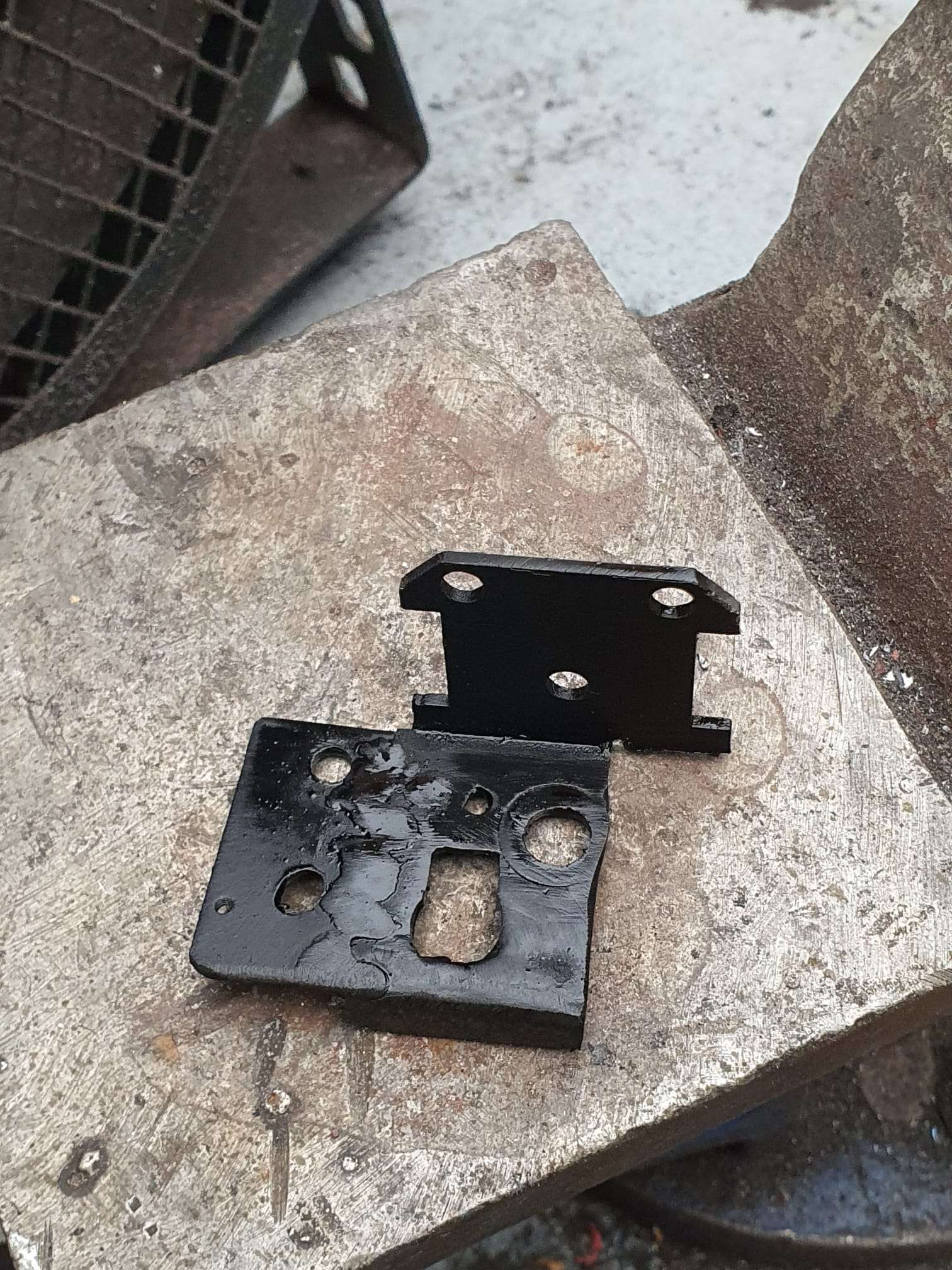
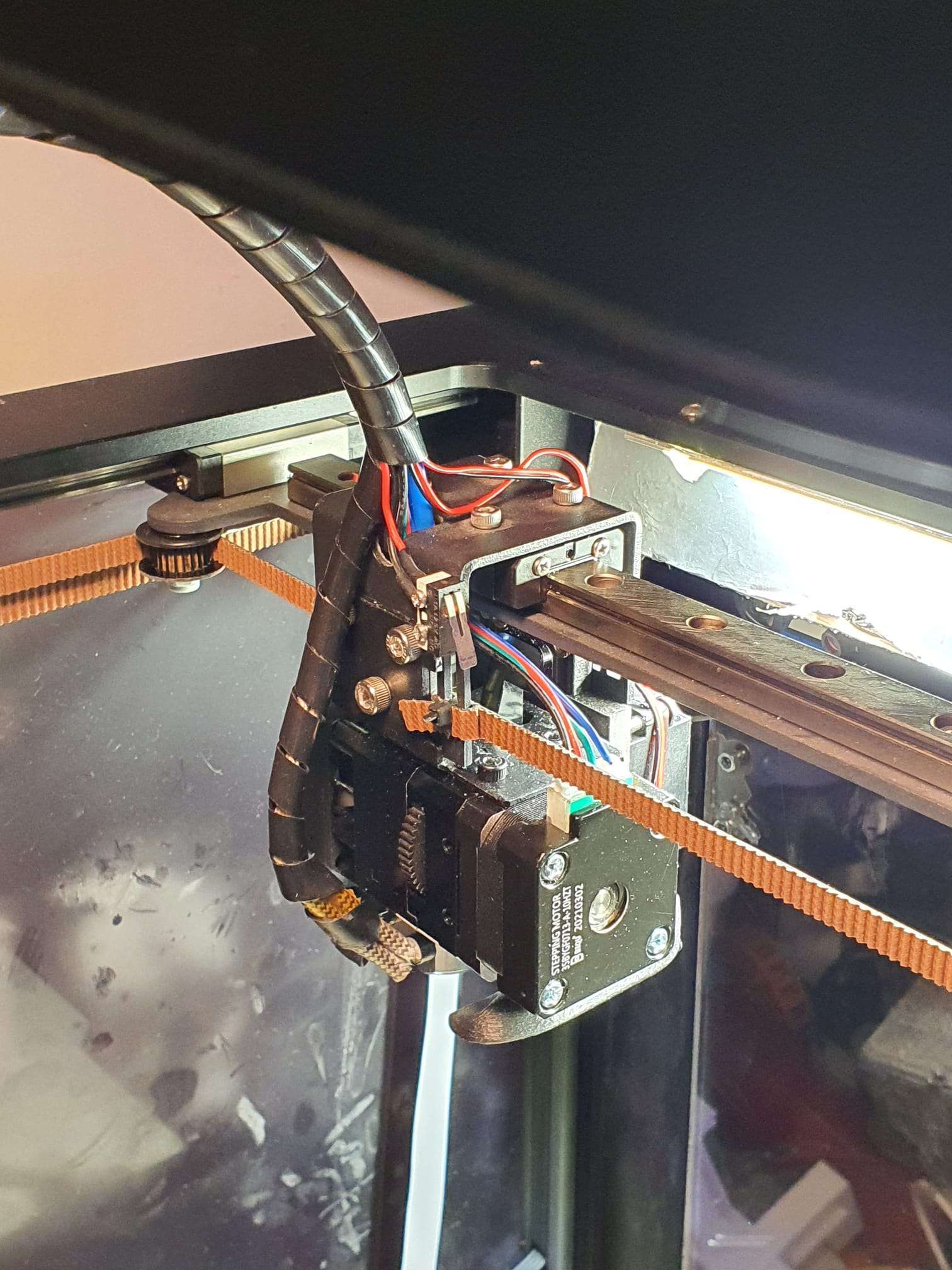
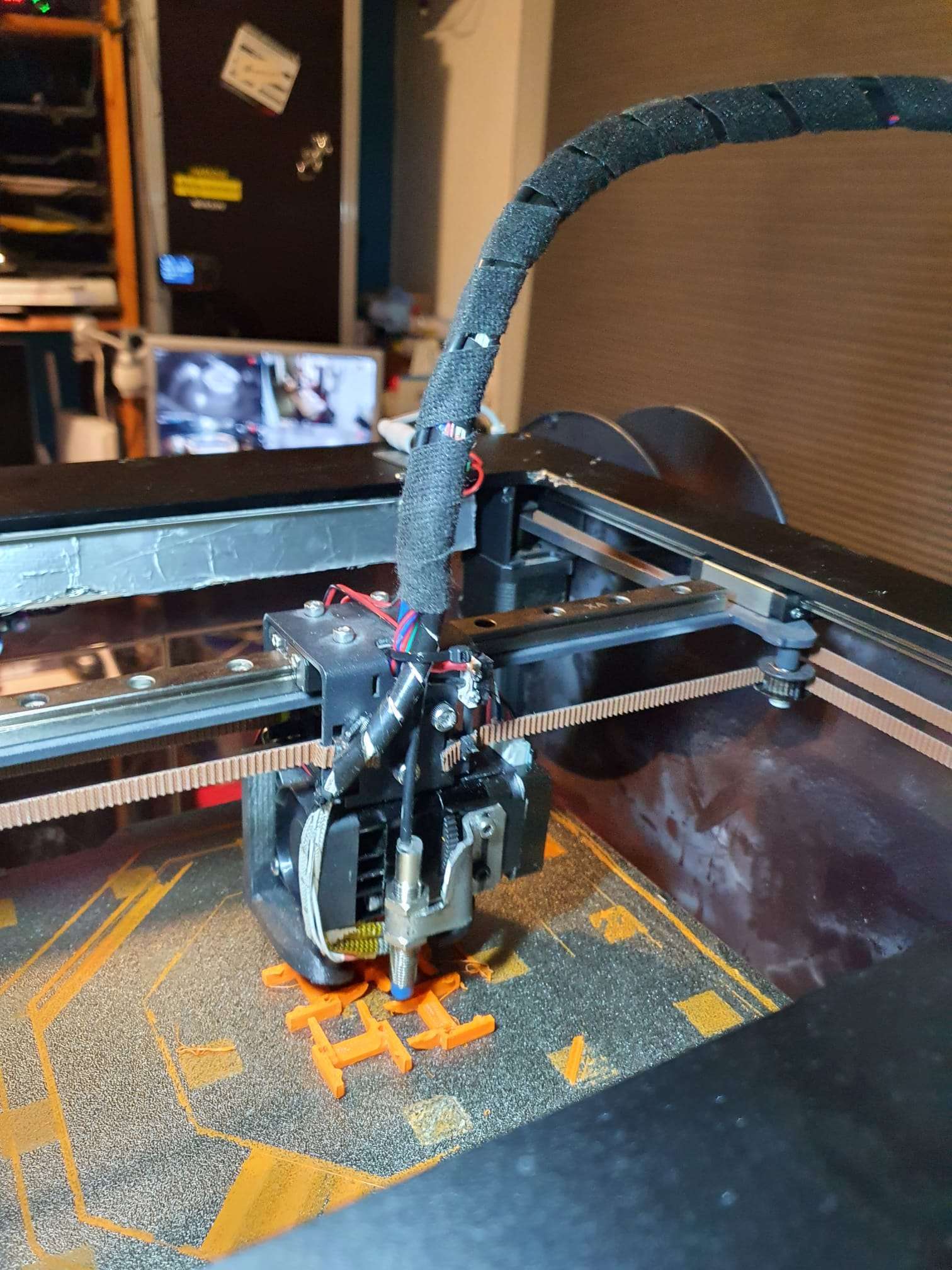
For the rest, please see the pictures. I re-used some of the old steel hotend mount, primarily the connecting plate with the XY carriage and the cornered horizontal plate.
In the old big bowden tube hole I welded a 6mm inner- and 12mm outer dia ring in.
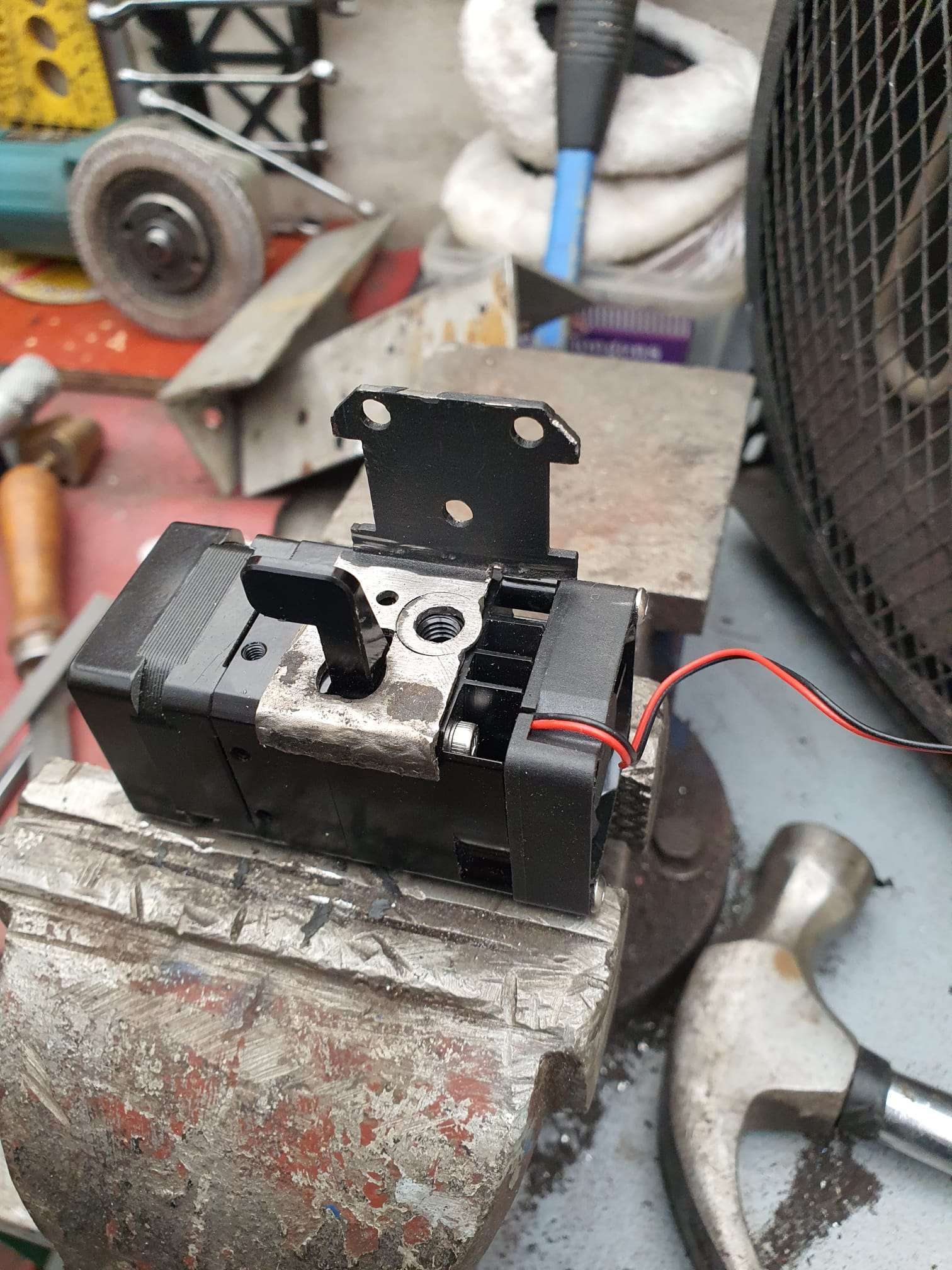
And I extended the horizontal base with a little piece of plate to use the 2 pieces 3mm threaded holes of the extruder’s upper side to bolt it all together.
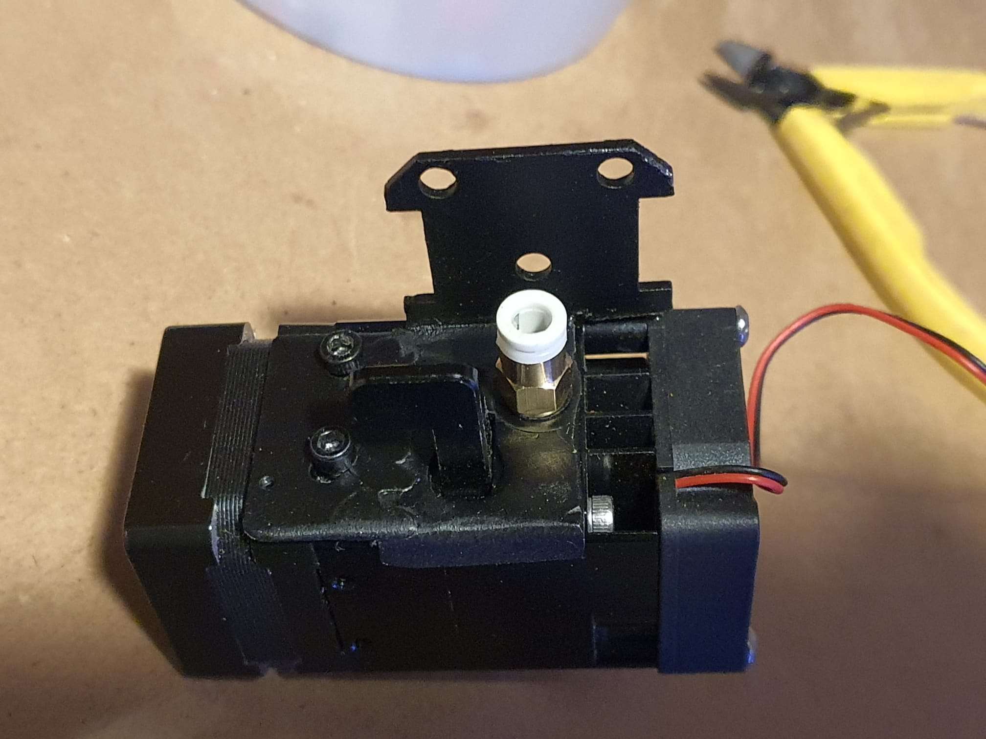
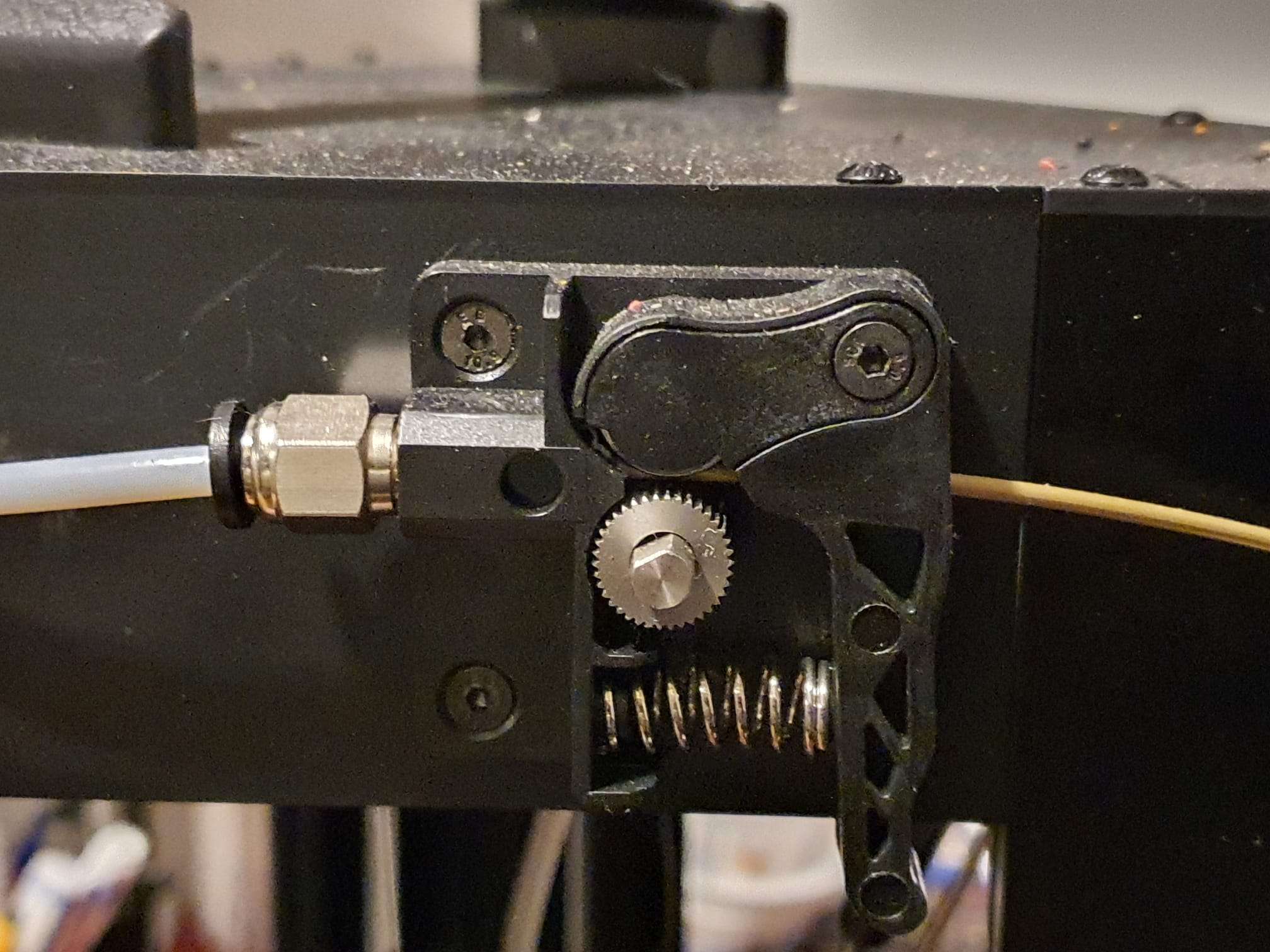
The filament input of the extruder has a screw-in nut with a 4mm clamp for the ingoing 4mm tube, and this is the other mounting bolt to hold the extruder to the mount.
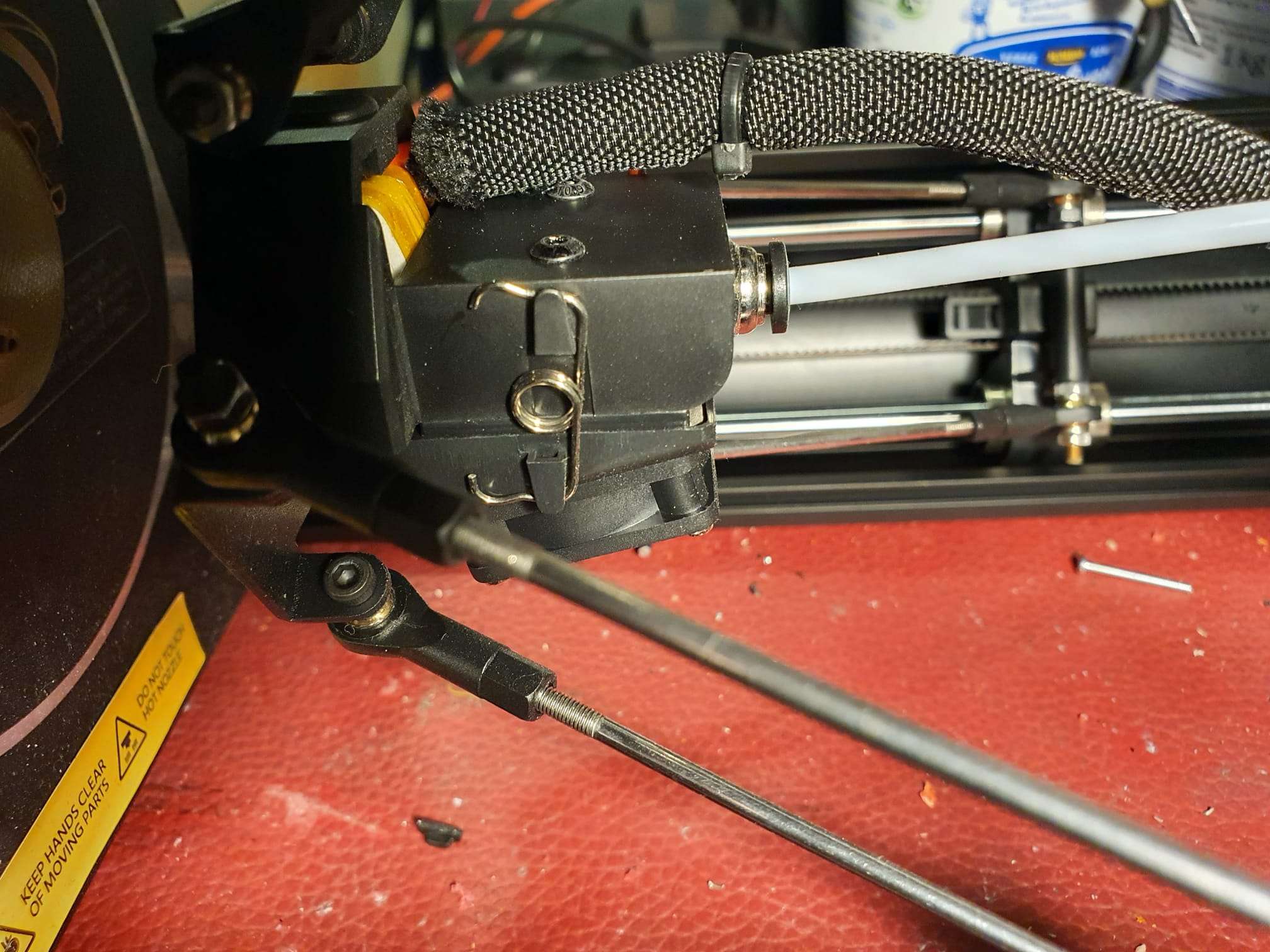
The original TT S pro hotend mount, freed from the parts I re-used to build the BIQU H2 mount.Cut the re-used pice to size, took some material out for the lever and fitted the ring in the 12 mm hole, to be welded.New mounting plate with welded ring at the right, and left an add-on welded little piece with the 2 holes for the mounting M3 screws.Extruder mount readyThe first fit. My goal was to get the nozzle tip at exactly the same XY position as original. And that worked perfect!Mounted the toolfan holder. I modded this to be put INSIDE the carriage instead of on the outside. I used 2 threaded M3 weld-in inserts in the toolfan holder.Ready. The rear fan is reversed as intended. I took some material out of the holder to let the rear fan rotate freely, since it was not capable of this in the original setup.
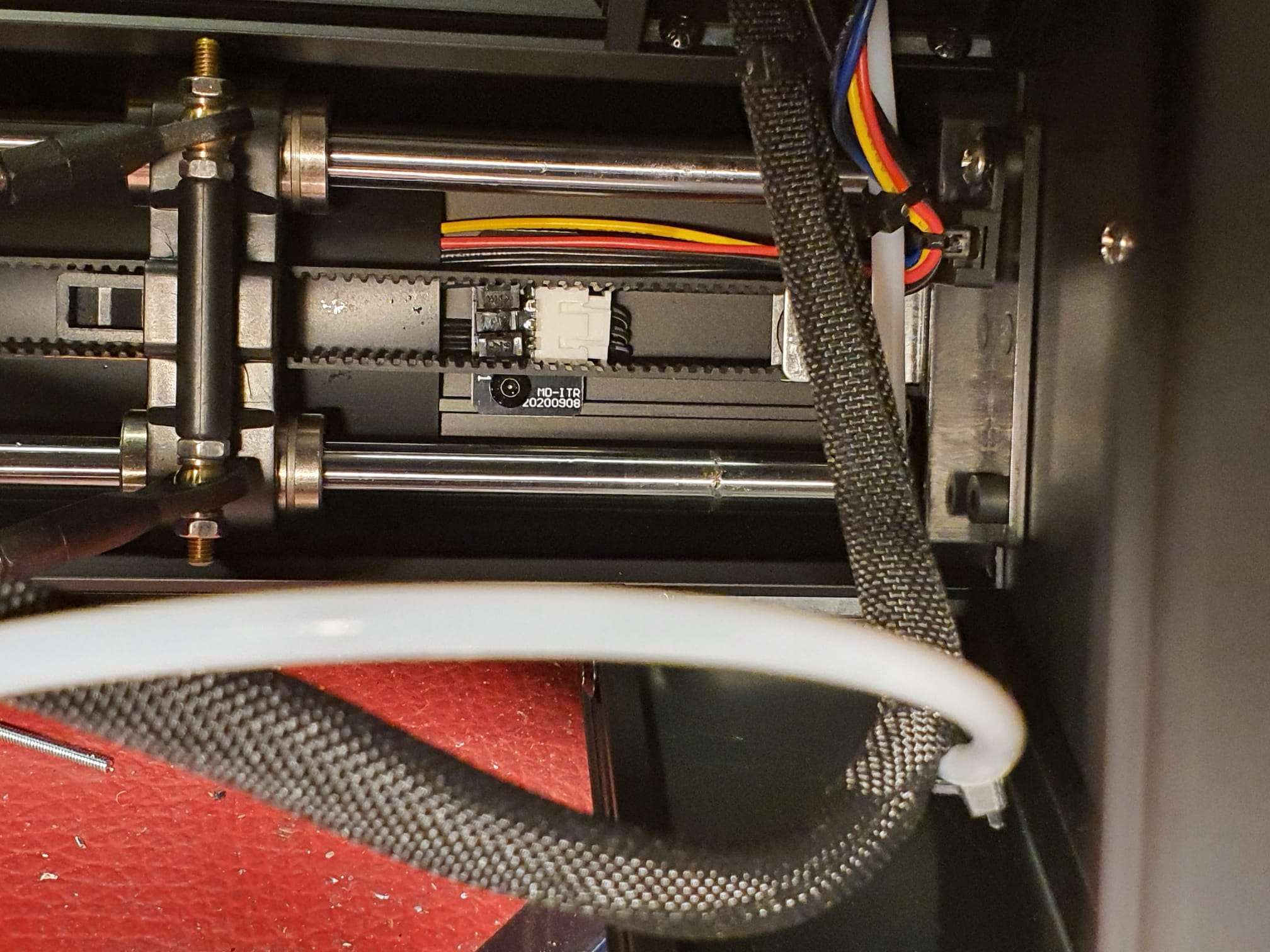
And the inductive 8mm probe, at the rear of the extruder setup. Works perfect!
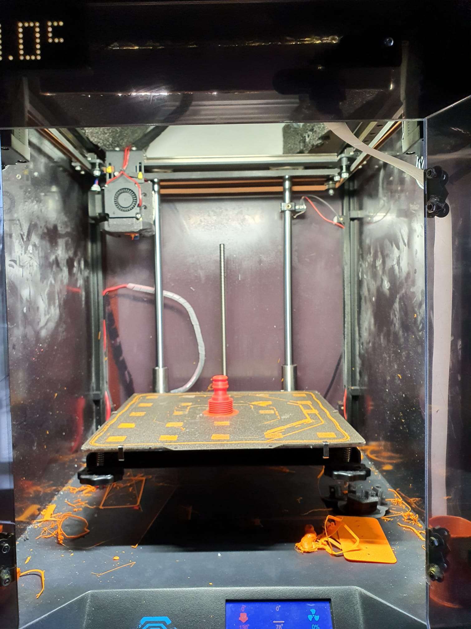
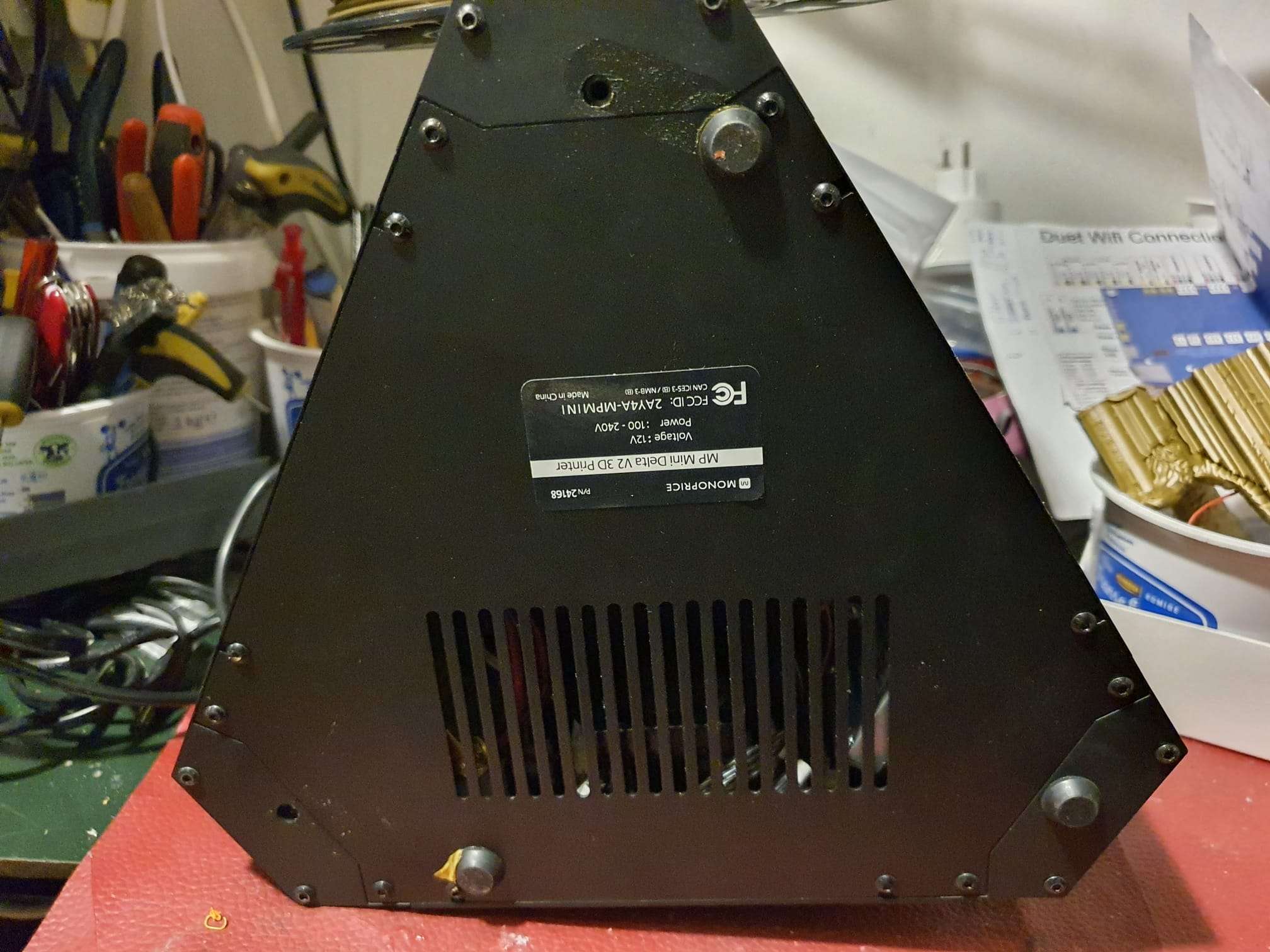
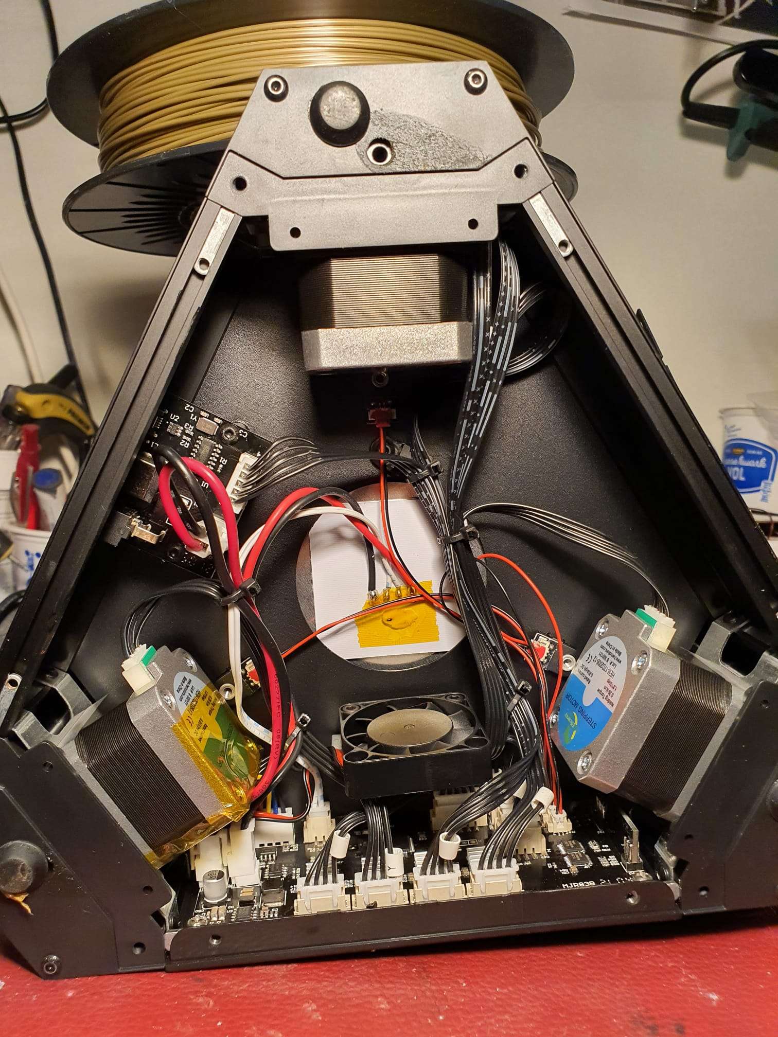
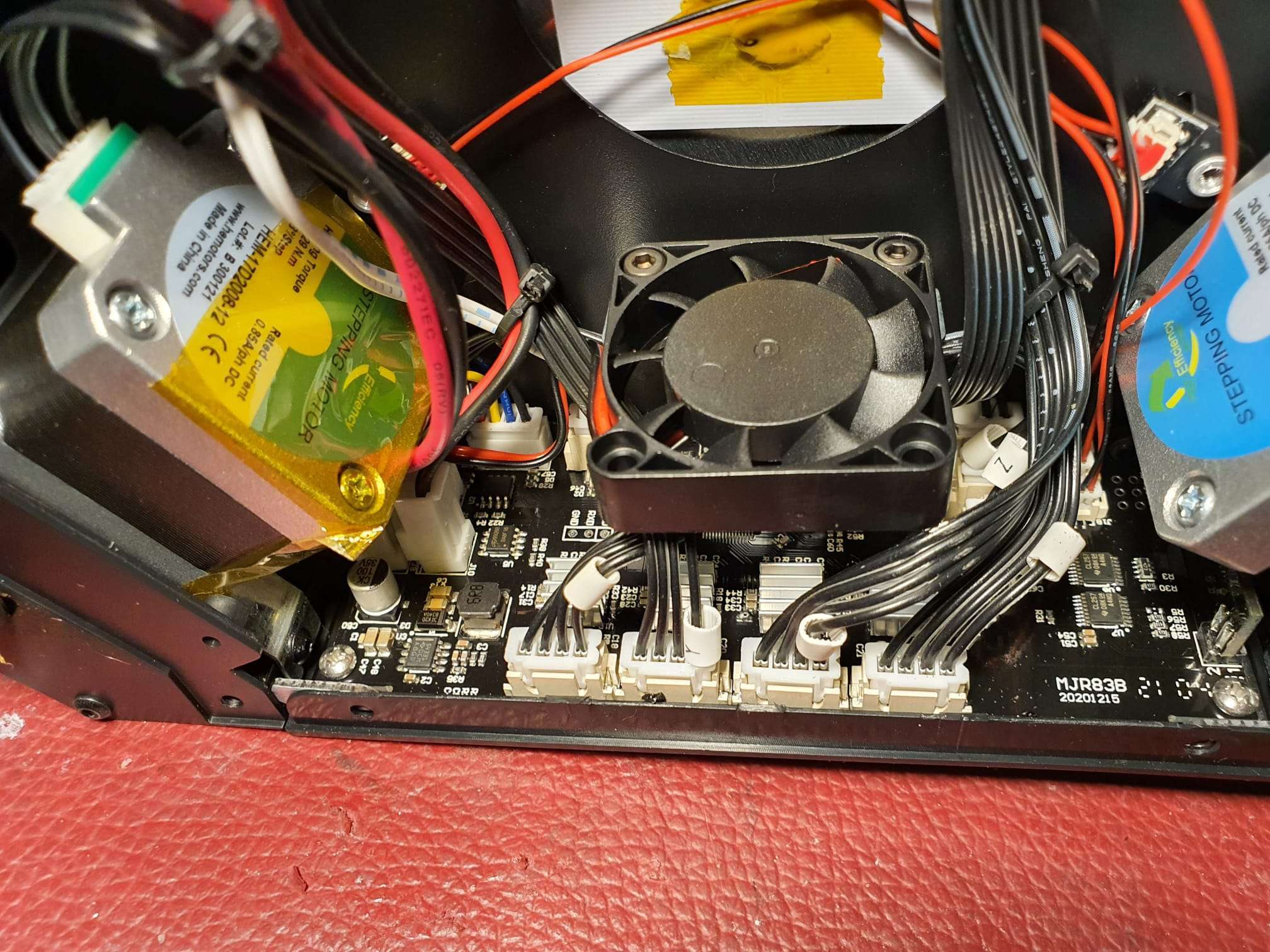
Today I opened the lid under my Monoprice Minidelta printer that I bought on Amazon end of last year (11-2021).
Unlike what I found on the net, I appear to have an upgraded motherboard that is joined with the TFT.
Both the MB and TFT have their own pocessor and -TFT update files, available from the Monoprice website and to be found on http://mpminideltav2.com/doku.php?id=octoprint:config.
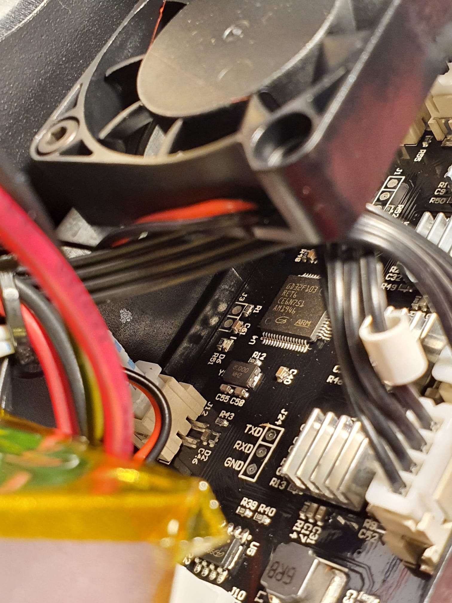
The GD32F103 ARM processor is the 32-bits direct STM replacement and is a very capable processor. The board also looks very good, so I won’t be replacing any of it.
I am however trying to build my own firmware for the MB, based on Marlin and the STM32 lookalike. BUT- the LCD and the pin connections for the hardware ia all unknown to me, so it might take some more investigations..
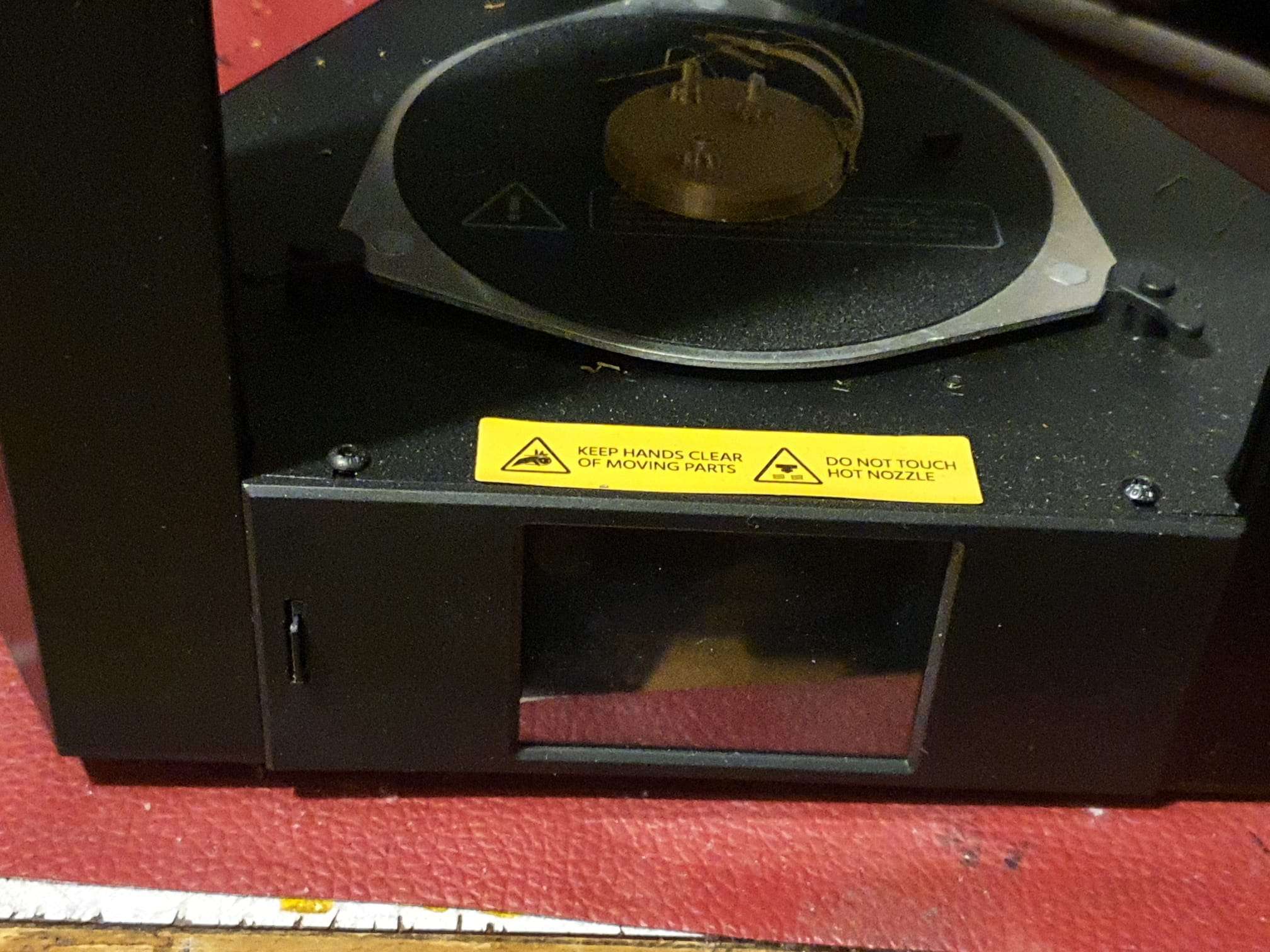
For the short term, I will install a Pi Zero2 and adjecent PI IR camera in the printer, along with a top LED light. The original new printer’s firmware allows the use of Octoprint so I can add this printer easily to my managed stock of remotely managed 3d printers. Without modding the original firmware.
In the bottom of the printer, enough space is available to mount the RPI and I will switch the LED with the PI’s GPIO managed switches, and a MOSFET board. Preferably with a PWM driver, or just on/off if this works better.
Another required upgrade will be to get a PEI sheet on the hotbed and replace the plasticy extruder with a dual drive one..
Ever since my kids got an interest in lomography early 2021, it started itching in my head.
I have a lot of analogue photo equipment stowed away, just because I can never throw anything away that might possibly turn out to be useful someday.
So- I got a supplier for my juices and film and I tried reviving my cams. That turned out to be more difficult than I expected.
The T70: no problem, just put 2x AA batteries in it and it’s OK.
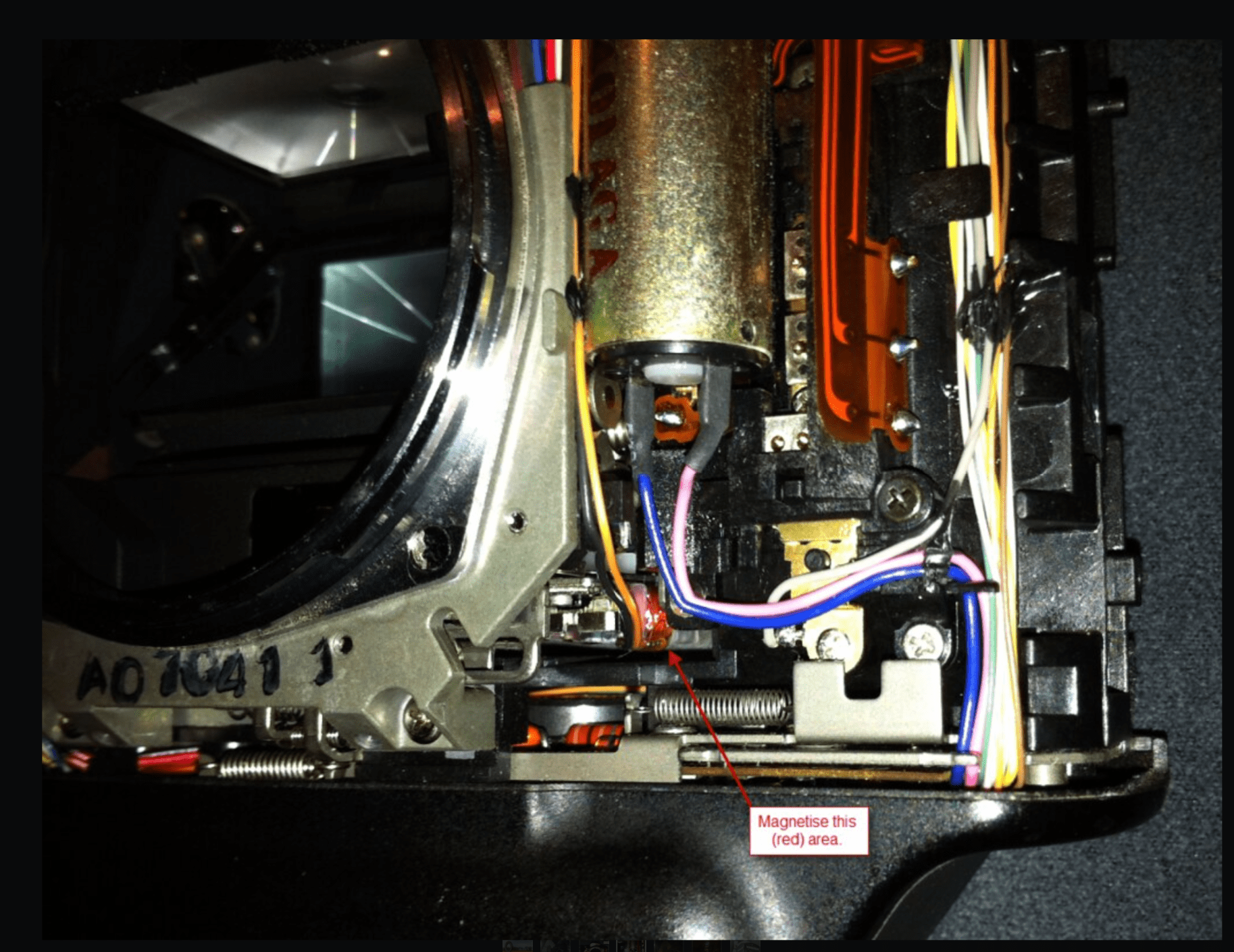
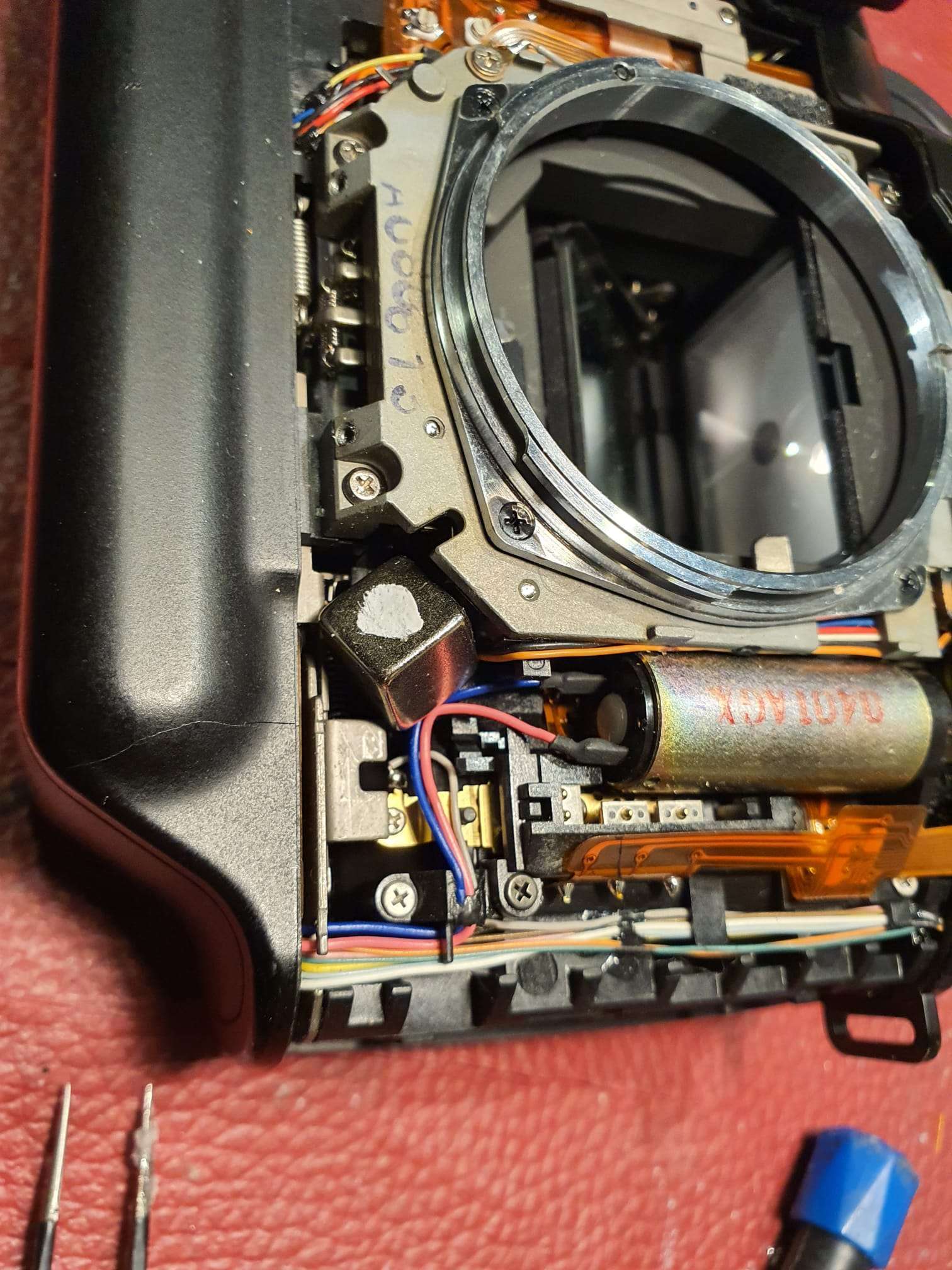
But-my favourite T90’s just would’nt fire any shots. After a lot of reading on the net, I finally found the problem: One of the coils appeared to require some magnetism from a nedymium magnet and all works well again!
So I did this and it worked. Actually, I removed the magnet and the camera kept working for some time.
But next day I had to do the same ritual again. and again.
Here’s the largest Neodymium magnet I used, with the white dot on top. It only worked well in this exact position. Any other side up and it would not work well. Turning the magnet also made the magic repair disappear. I left it in a couple of hours and the shutter kept working. Shut it off for the night and it would no longer work next morning. The magnet can’t stay in, obviously since it is blocking some other moving parts.
So- the T90’s are in the storage again.
And- My newer Eos 500 worked perfectly! Everything automatically, AF and all! This is just a modern camera that has all you may need. The EF lenses all fit so I can start shooting with this 35mm cam, again!
I will only do B&W, since my enlarger and all of my dark room equipment is for B&W. I received the needed liquids last week, and I’m ready to go!
I will add new posts and add the links above when I start developing my first roll of 35 mm film, in black and white !
2022-02-10: FIRST ENCOUNTERS – RZ67 system & APTUS leaf 65
Recently I received some extra money to persue an old dream:
Get a medium format camera with a digital back and make some awesome architectural pictures!
I know that the Hasselblad/ Zenza Bronica/ Mamiya/ Phase One and some other’s medium format camera’s can produce awesome results, and that they are mainly used for non-moving os slow moving objects.
But- I am more of a digital type than analogue.
So-I really wanted a Hasselblad sort of camera with the awesome 39Mpix digital back.
But my budget is limited, so I had to get my wishes adapted to my budget.
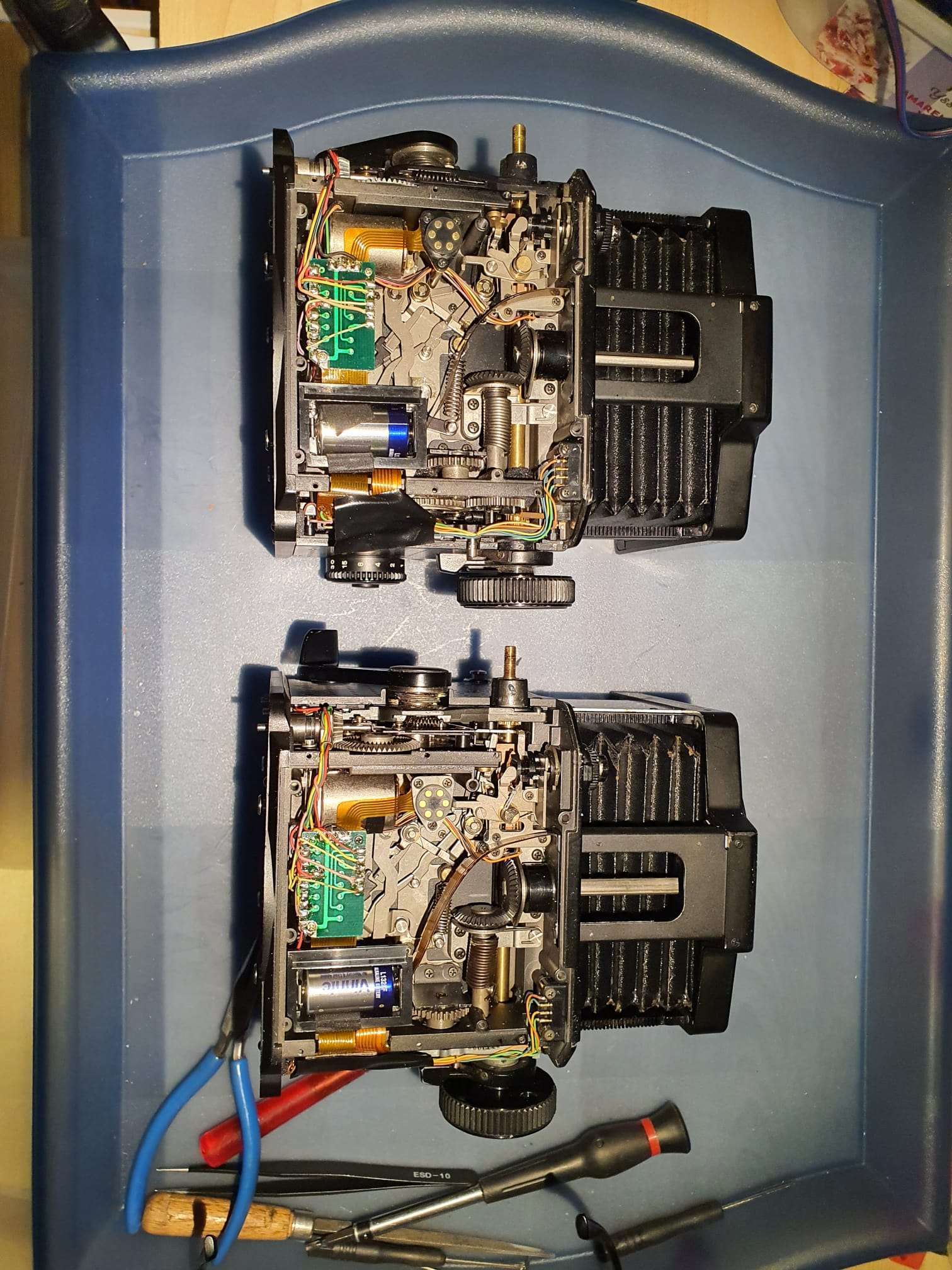
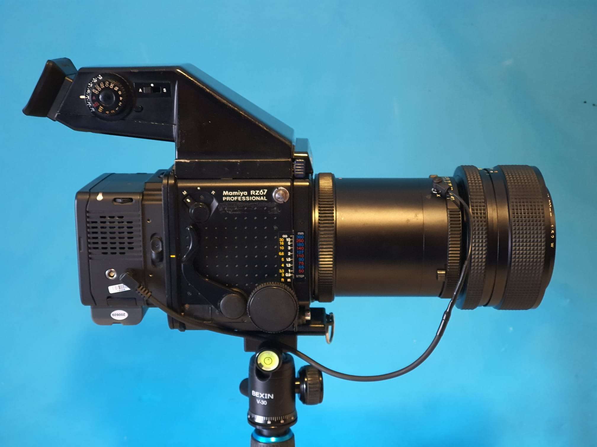
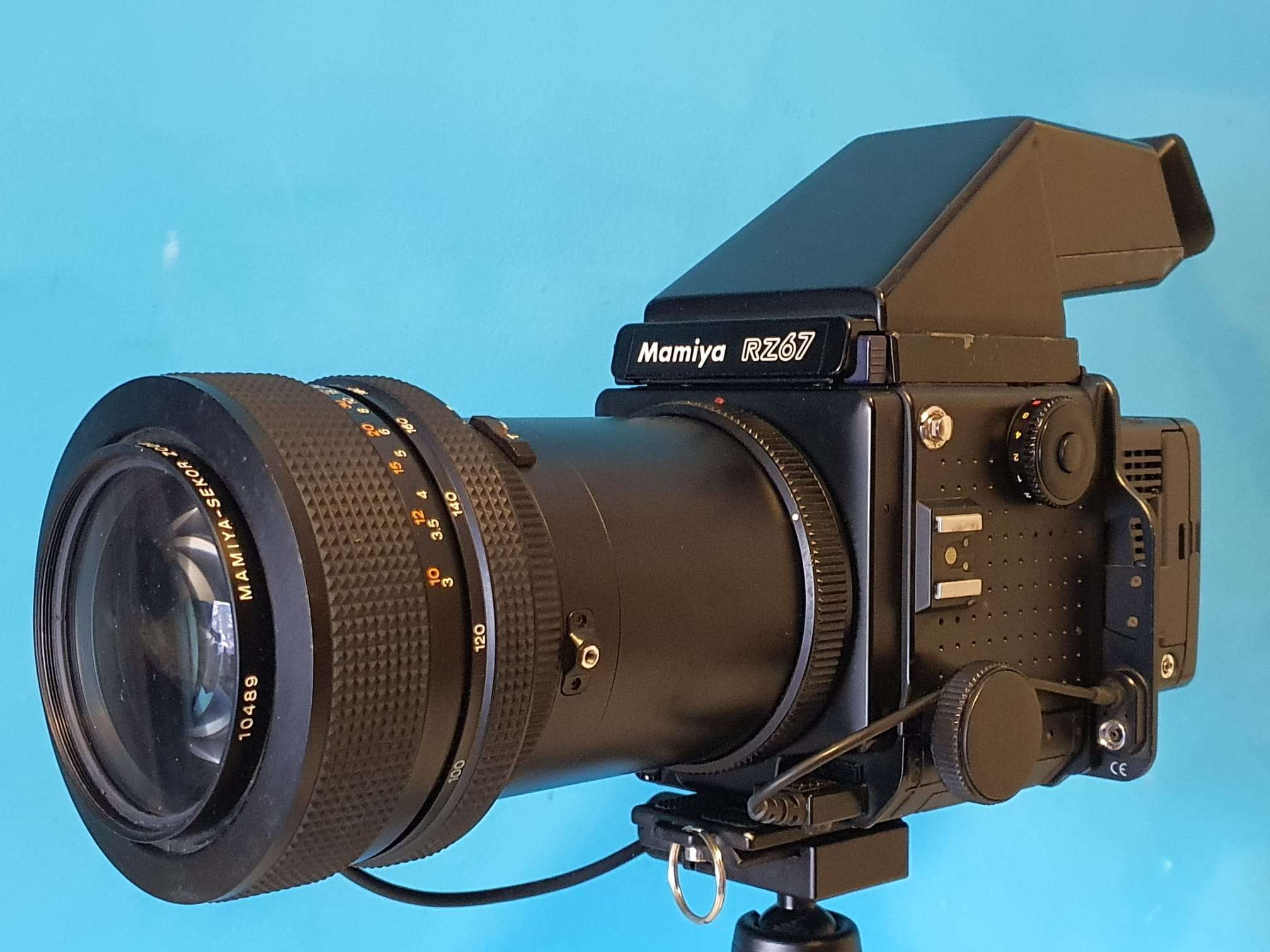
In the end, I ended up with a set of Mamiya RZ67’s, both with a known problem so I could make 1 working camera out of 2 non-fully functional ones.
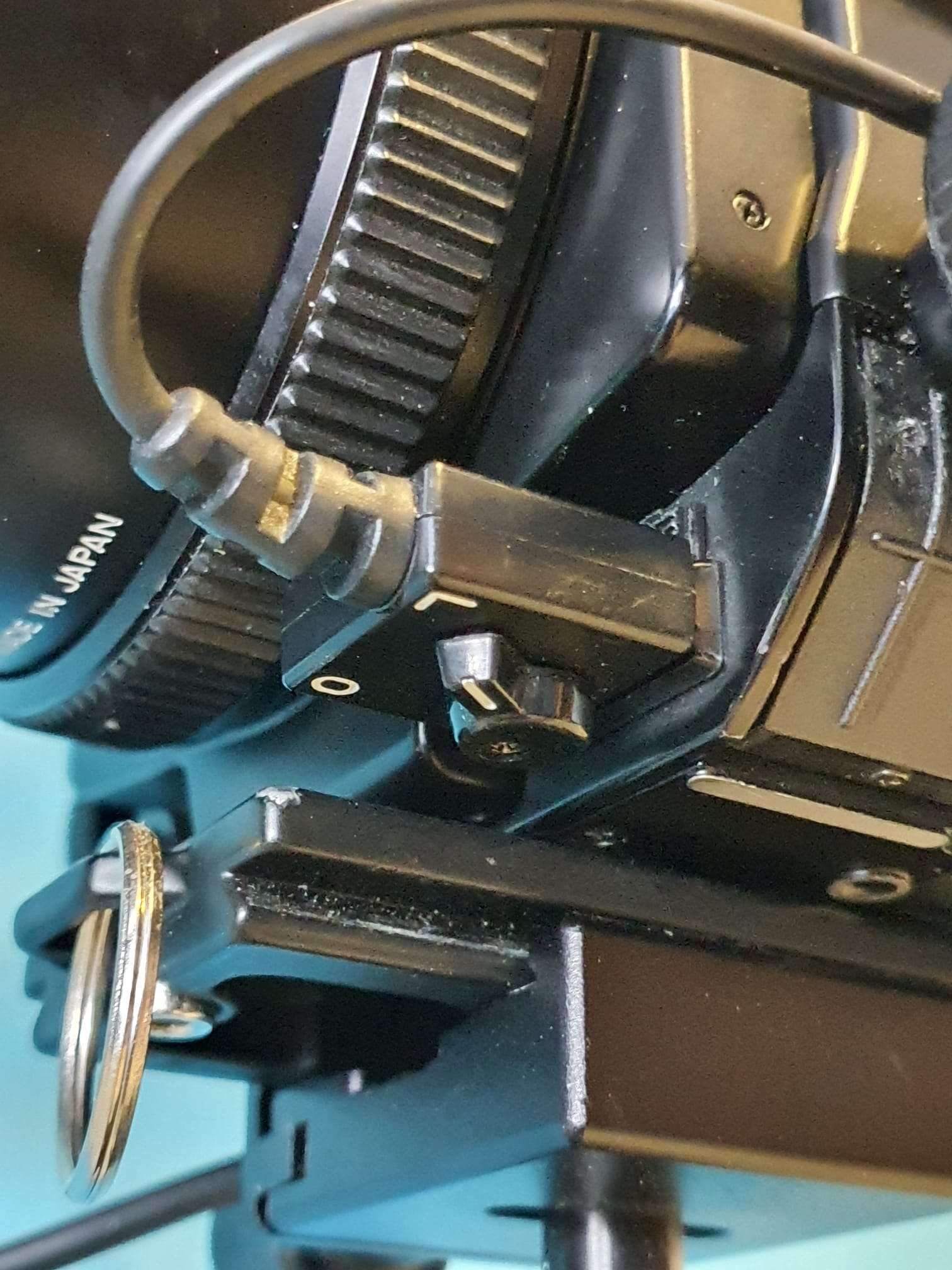
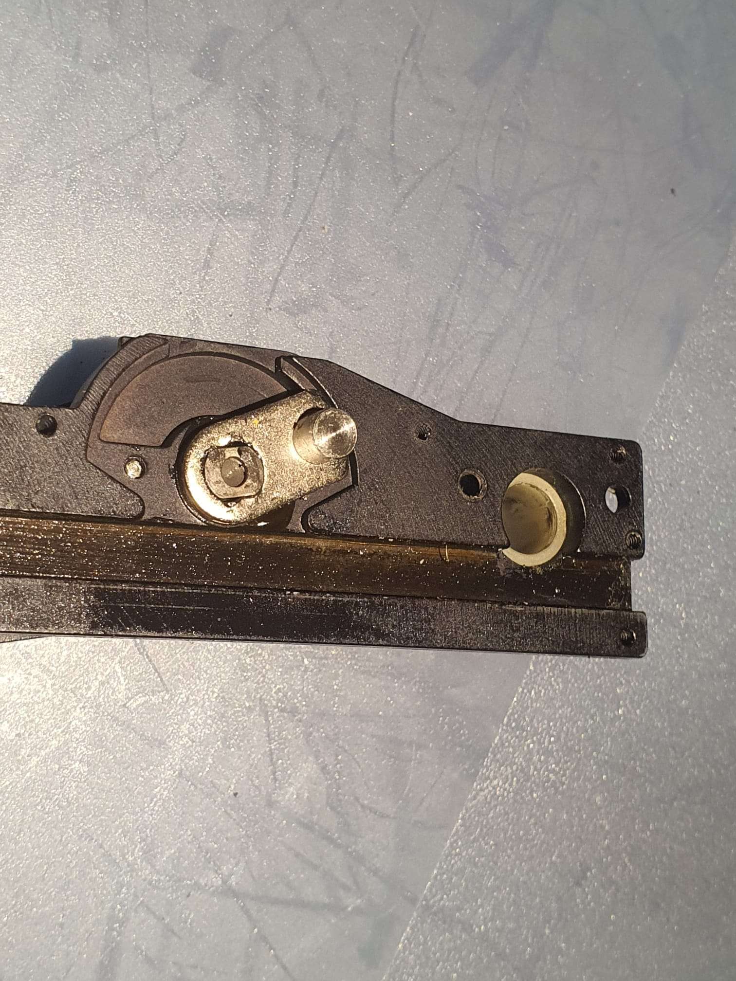
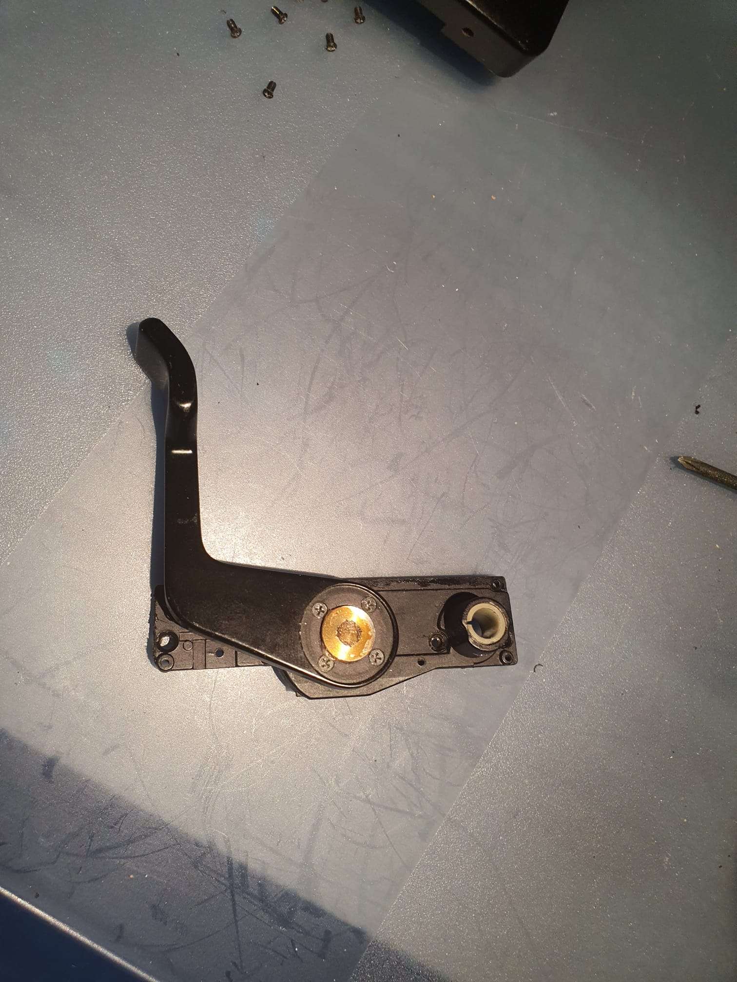
I exchanged the bellow from the 1 to the other camera, so this one is now in full working order. the donor camera has firing issues. I will repair the donor later. I downloaded the repair manual for the RZ67 camera and it is extremely well documented in English, including pictures and all.The donor camera has a plastic shutter cocking handle whereas the receiving camera has a metal one. which btw has somewhat another shape. The donor’s handle (shown in the above picture) has quite some play on the handle and I expect this to be one of the main problems to be solved.
The repair went very well and within a period of 4 hours I had 1 completely working operational RZ67 camera and 1 donor camera with a lot of loose parts, that I will repair upon receival of the new bellow I ordered from AliExpress for 70 Euros.
The camera’s were acquired from Japan, like most of the other parts except the digital back that comes from Sacndinavia:
4 Lenses (50mm, 110mm, 100-200mm and 250mm);
An original 1.4 x teleconverter;
Both original wired extension tubes for macro photography;
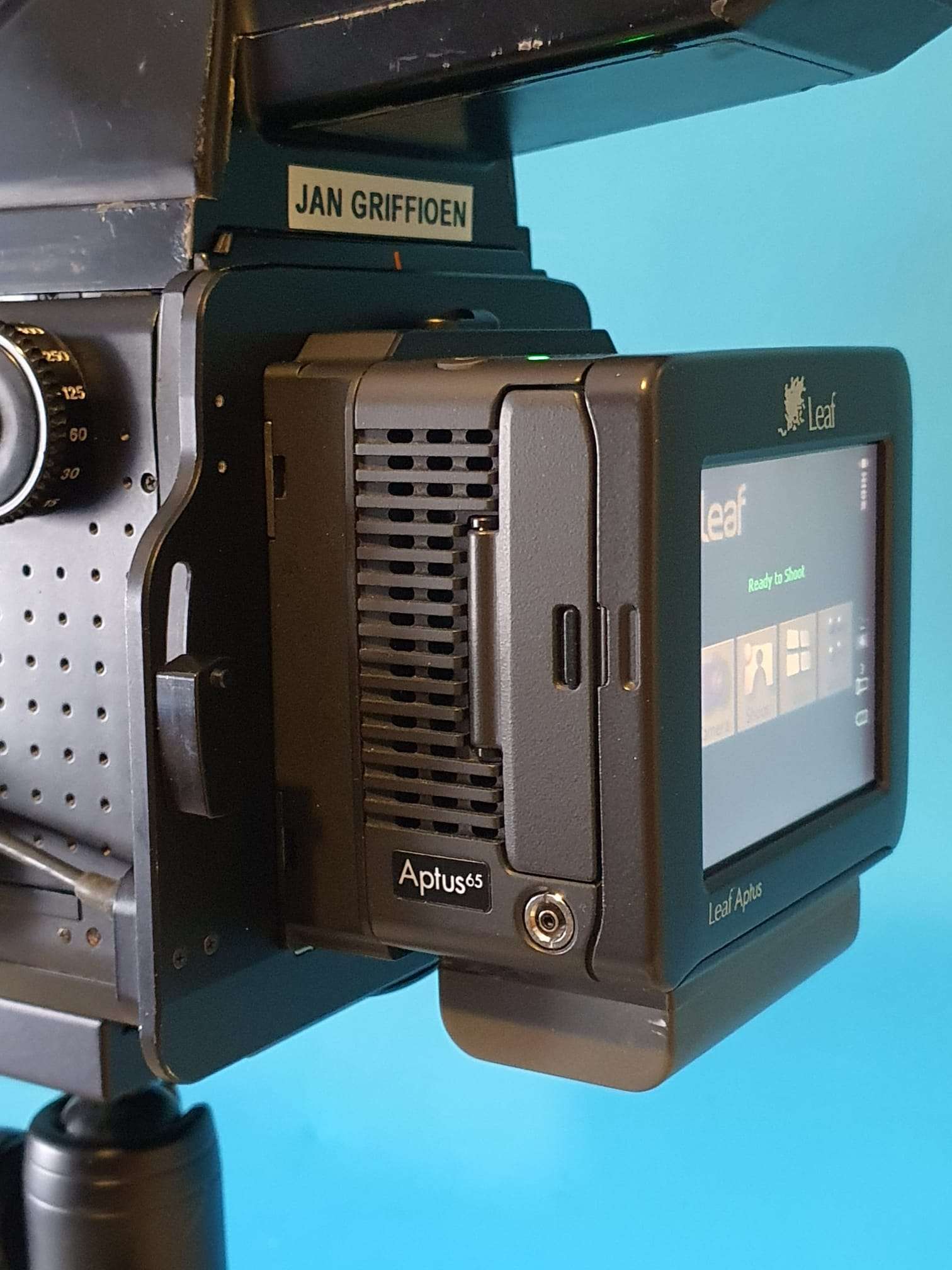
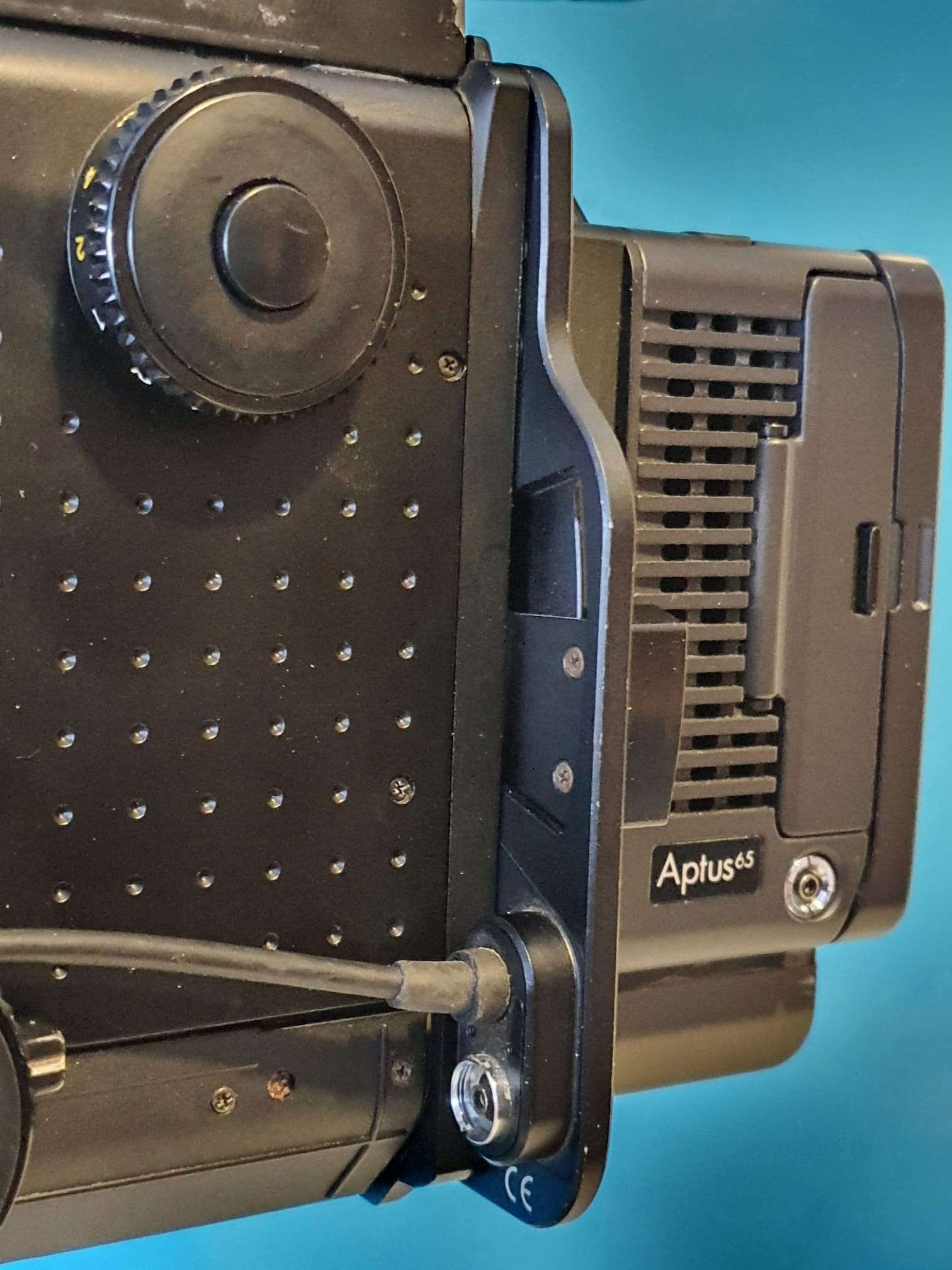
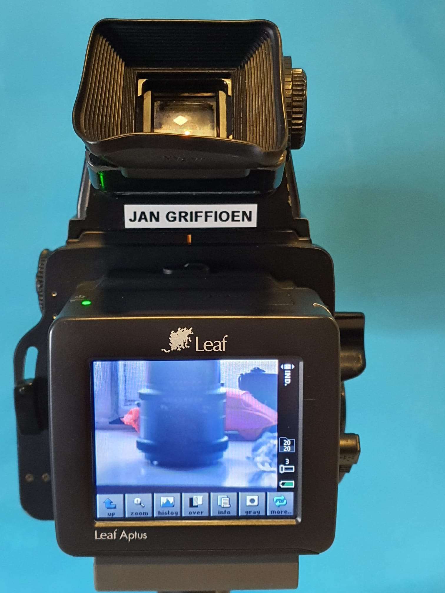
A Leaf Aptus 65 V-mount 28 Mpix digital back;
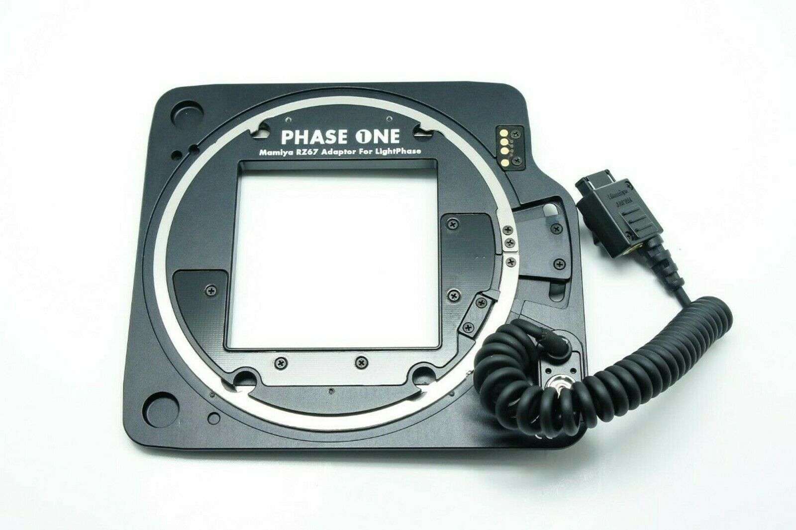
The required adapter plate from Phase One to convert RZ67’s back to V-mount;
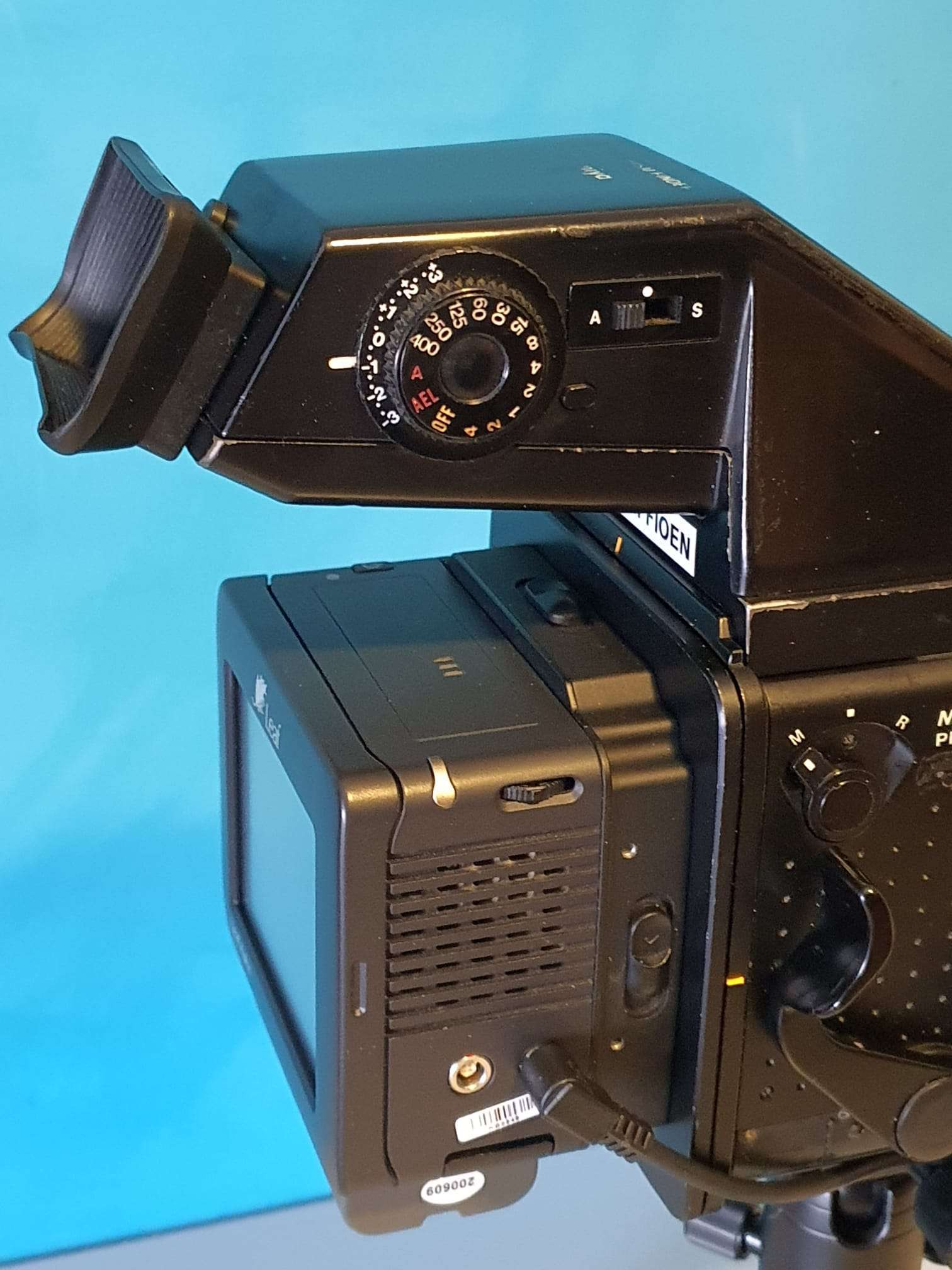
Plus a lot of accessories like a left handgrip, an AE diaphragm viewer that enables automatic lighting (Aperture prio-only where the shutter speed is automated) , belt diaphragm viewer, film back 60x70mm and so on.
I got the lenses from ebay, and two of them really need some internal cleaning.
The one that works best is the 250mm lens.
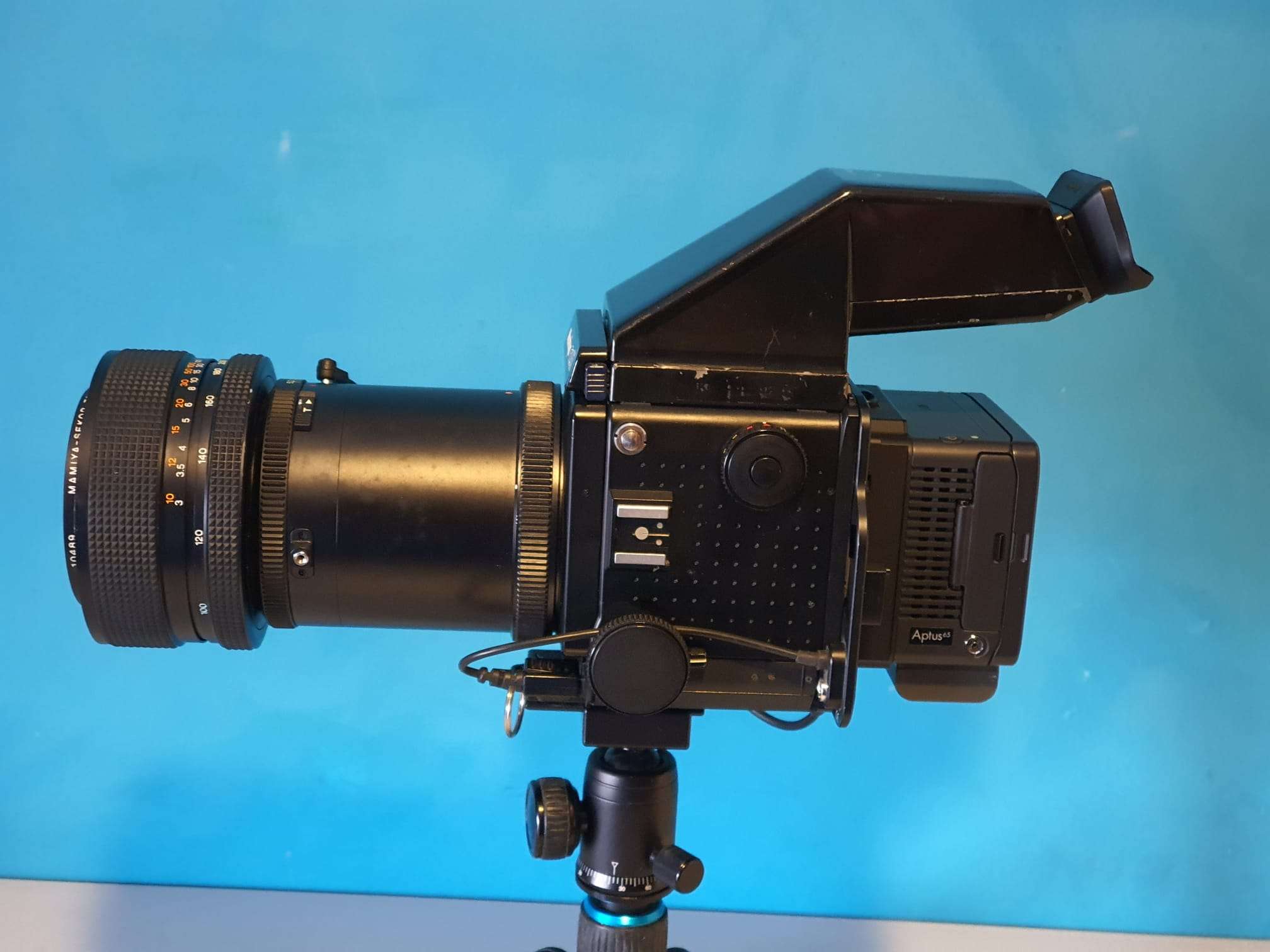
I got some pictures taken right after everything got mounted on the rig, through the window at home.
I used the AE finder on Automatic, and set the lens’s aperture at 32 to get the sharpest details.
The automatically generated (and set) shutter speed when the position switch of the AE prism viewer is set at ‘A’ in broad daylight against the clouded sky turned out to be around 1/15 second which seems quite long.
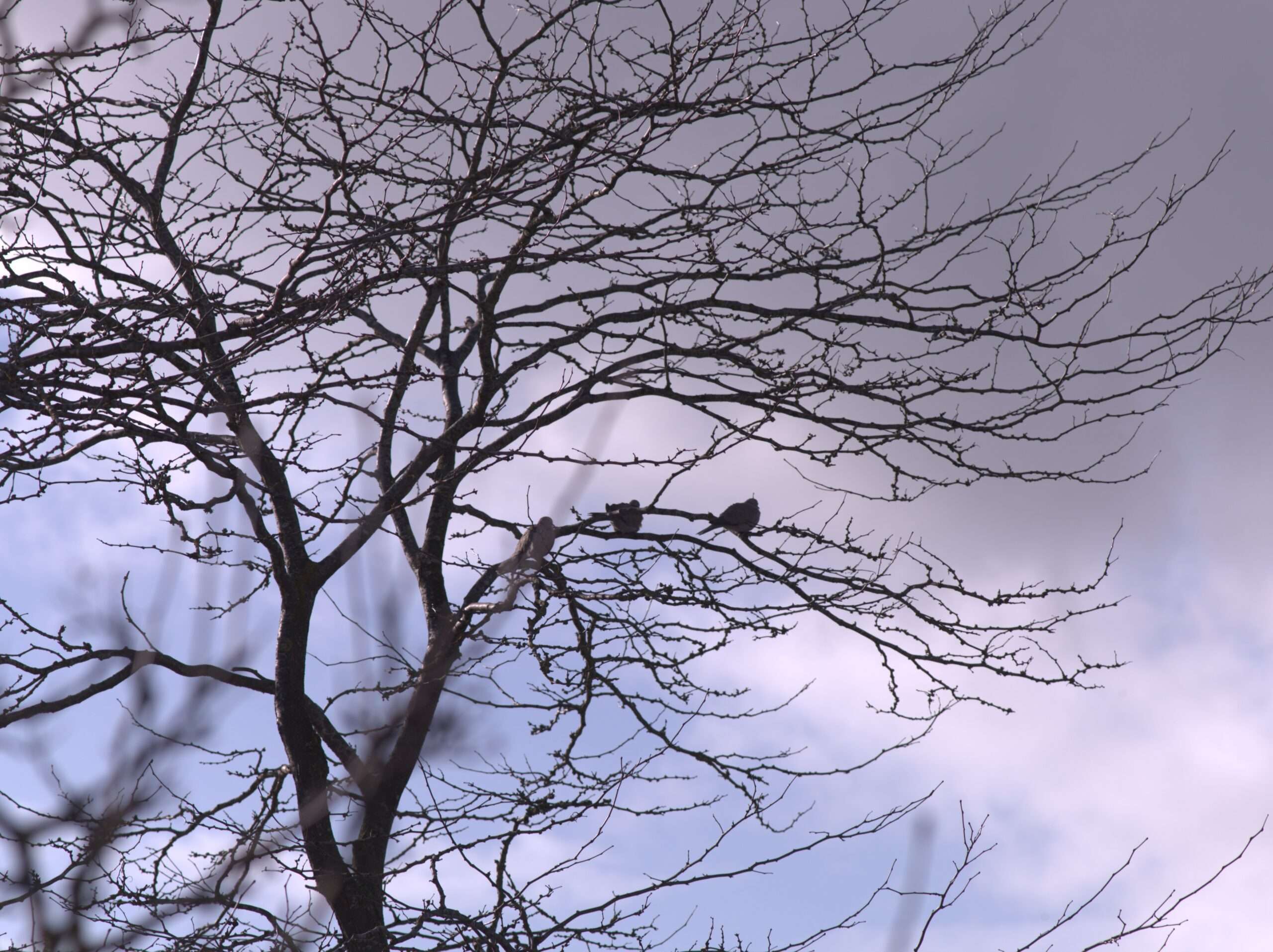
And the picture of the tree branches with some birds sitting on them turned out beautifully!
This tree is about 100 feet from my house (30 meters), and the couple of branches fill all of the screen, so the telephoto power of this combination is working very well.
This first digital photo that I made with my RZ67 digital kit and the 250mm Z- Mamiya lens is shown below:
Another thing to get investigated is that the 50mm lens does not get well into focus at all.
Like the front of the camera does not get close enough inside the camera.
The 250 mm works awesome and the 100-200 is fine as well, since this lens has its own focusing ring at the front of the barrell.
What I could not get to work -yet- is the ISO setting. If I set ISO on the Aptus to 400, the AE system of the RZ67 does not recognise this, since I get overlighted images.
I adapted this by setting the lighting correction to +3 on the AE viewfinder which made me produce OK pictures but this does not solve my original issue, since I want it to work automatically.
I really want to use this setting, instead of compensate for it so the Aptus gets less light. Still working on this.
I will measure the adapter’s electrical output on the right pin for the signal to change, like the analogue filmbacks do when you change the ISO settings.
If needed, I can hook up a small switch to the adaptor for ISO settings.
But I am sure it has something to do with settings in the Aptus 65, since you can configure almost anything and I am still finding out what I need to set for this to work properly with the Phase One converter plate.
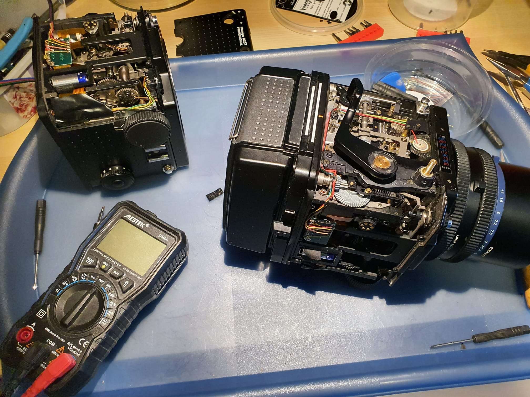
The complete setup looks like this, with the 100-200 mm zoomlens attached:
I will not be running around with this outside, since the combined weight is over 4 kilograms. Just too much if you want to seriously shoot anything that is any good.
This will be my studio-, & macro-, and architecture camera since the shallow depth of field will produce amazing pictures, both in B&W and in color.
Maybe a commercial photograph session now and then, I believe that getting a technical factory shot with this cam/combination could turn out to work very nice!
Compact Flash cards: I used an adapter from CF card to SD card that I also use on my Canon 5D MarkII, and it only accepts SD cards up to 32 GB. But that’s OK. I will try to install the wifi SD card as well, since I have that lying arouns somewhere, I will add this in a new post later. The Aptus’s firmware had a setting for this, so I will try this anyway.
The digital back adapter for the RZ67 camera is not really visible between camera and digital back, underneath is a picture of the one I use. It is commonly available but requires a V-mount digital back. V-backs from Leaf or Phase one are very rare to get by, since they are either Mamiya fit (proprietary mount for for the 645 cams) or H-Hasselblad fit. And Hasselblads V-mounts digital backs are very good and fairly easy to get at, yet they are (in my view) very expensive due to their high quality and high pixel rates.
CROP FACTOR
The Mamiya Leaf Aptus 65 has a 44×33 mm sensor of almost 29Mpix. The Aptus has been made for the 6045 line-up and therefore all specs relate to that, and not to the RZ67’s 6×7 cm format.
The maximum (theoretical) film format on the RZ67 is 70x60mm. But the picture size with a 6×7 cm back will be 56mm x 69.2mm.
Even though, most common used on the RZ camera are the 6070 film backs, although a 60×60 is also available but hard to get for a fair price. The 6070 backs are the ones without anything in size labeled on top. Any 6060 or 645 sized back will have this size labeled on the pack’s outside.
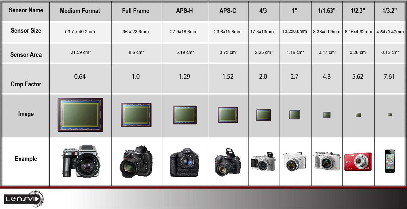
The Aptus 65’s crop of 1.3 is defined by Leaf in relation to the medium format definition and this is theoretically only 60x45mm but it is adjusted down, due to cutoffs and such. 60×45 camera size is measured in medium format picture size as 53.7×40.2mm.
The medium format is thus generally defined at 53.7×40.2 mm picture & sensor size, and its surface is 21.59cm2.
The Aptus 65’s sensor is 33x44mm and its surface is ‘only’ 14.52 cm2.
The crop factor of the Leaf Aptus 65 is 1.3 versus medium format.
The full-frame sensor against which all other image sensors are defined is 36×23.9 mm and its surface is 8,6 cm2.
So- even the fact that you won’t use the full width of the 6×7 cm range of the RZ67’s back panel’s covered projection space, the coverage of the Aptus 65’s sensor almost doubles that of a full frame sensor.
The used table is below:
I am, however, still out on the search for a Hasselblad CFV-39 V-mount digital back since it has the extremely good Sony sensor of 49×36.7 mm and it has great specs and image results. Still hesitating to buy this since the prices are above 3000 Euro’s, excluding import duties and VAT. So- adding this makes it cost over 4500 Euro’s. I am still searching for one within the EU, so I don’t need to pay additional costs before I get it.
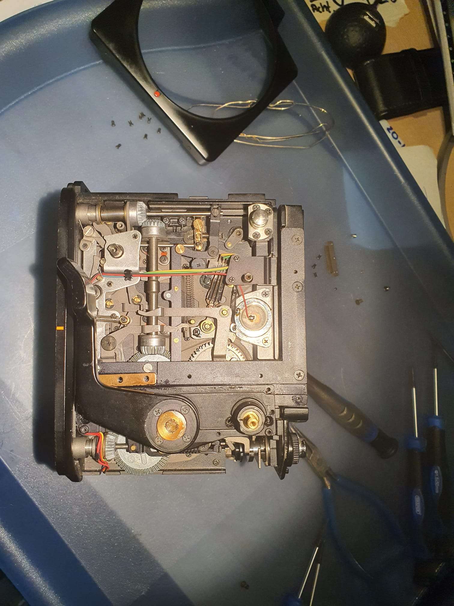
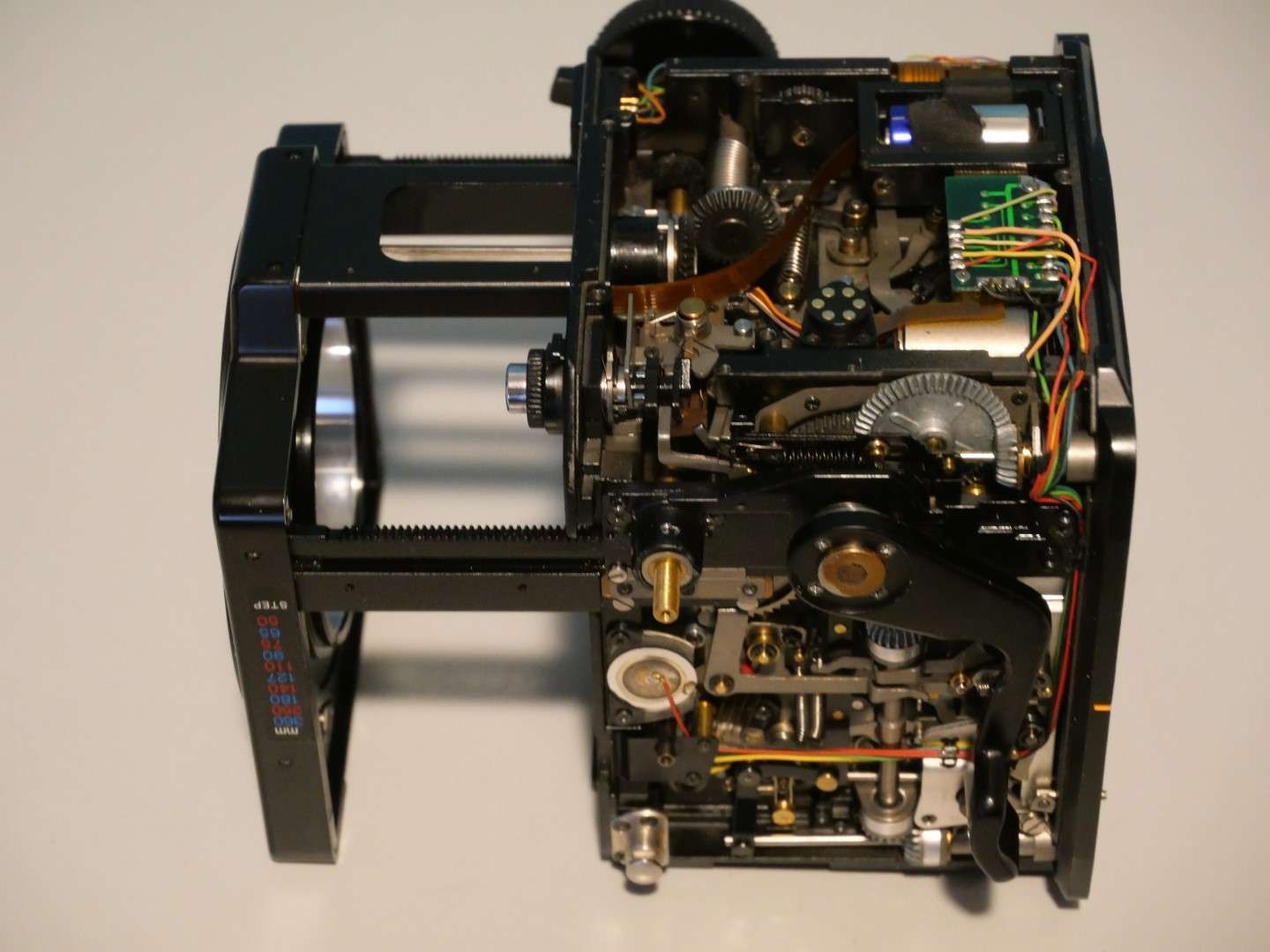
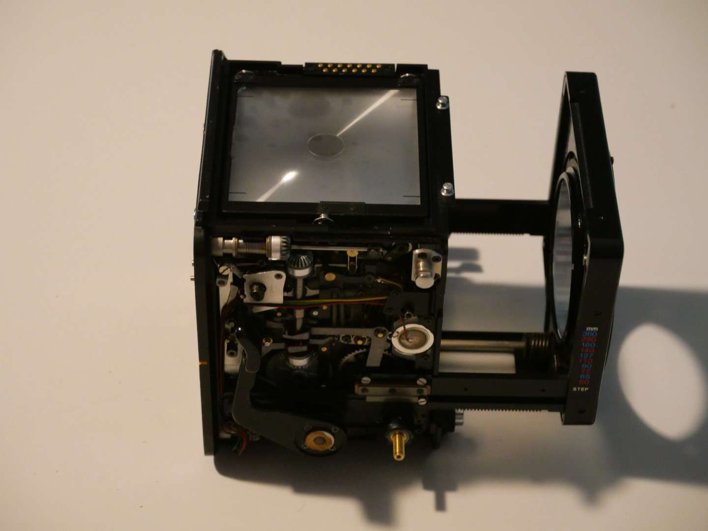
As you can see in the above MP4, the shutter cocking mechanism could not fully complete the cycle to the end of the cocking prcedure, due to play in the connection between the small flange and the rod on which it is placed.
I ended up by just using strong thread sealer, screwing it tight again an waited for 24 hours before using it again.
Together with the beneath shown repair of the external lever play, this indeed fixed the problem of not reaching the end of the cocking procedure.
And thus my donor RZ67 camera housing was working again, albeit only in emergency mode.
But I will explain the repair of this specific electrical problem(s) in yet another post.
And- also the same problem with the outside lever. The lever was easy to repair. I put it on my working table , on the flat part of my vice and used a blunt pointed driver and a dead blow hammer in the center of the small axle to punch it and this fixed the outside (big black) lever again firmly to the internal small lever.
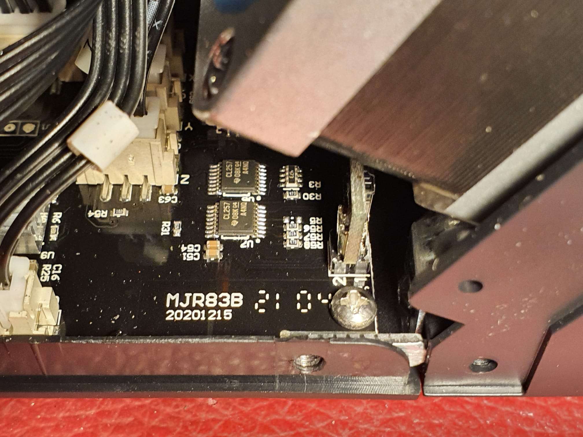
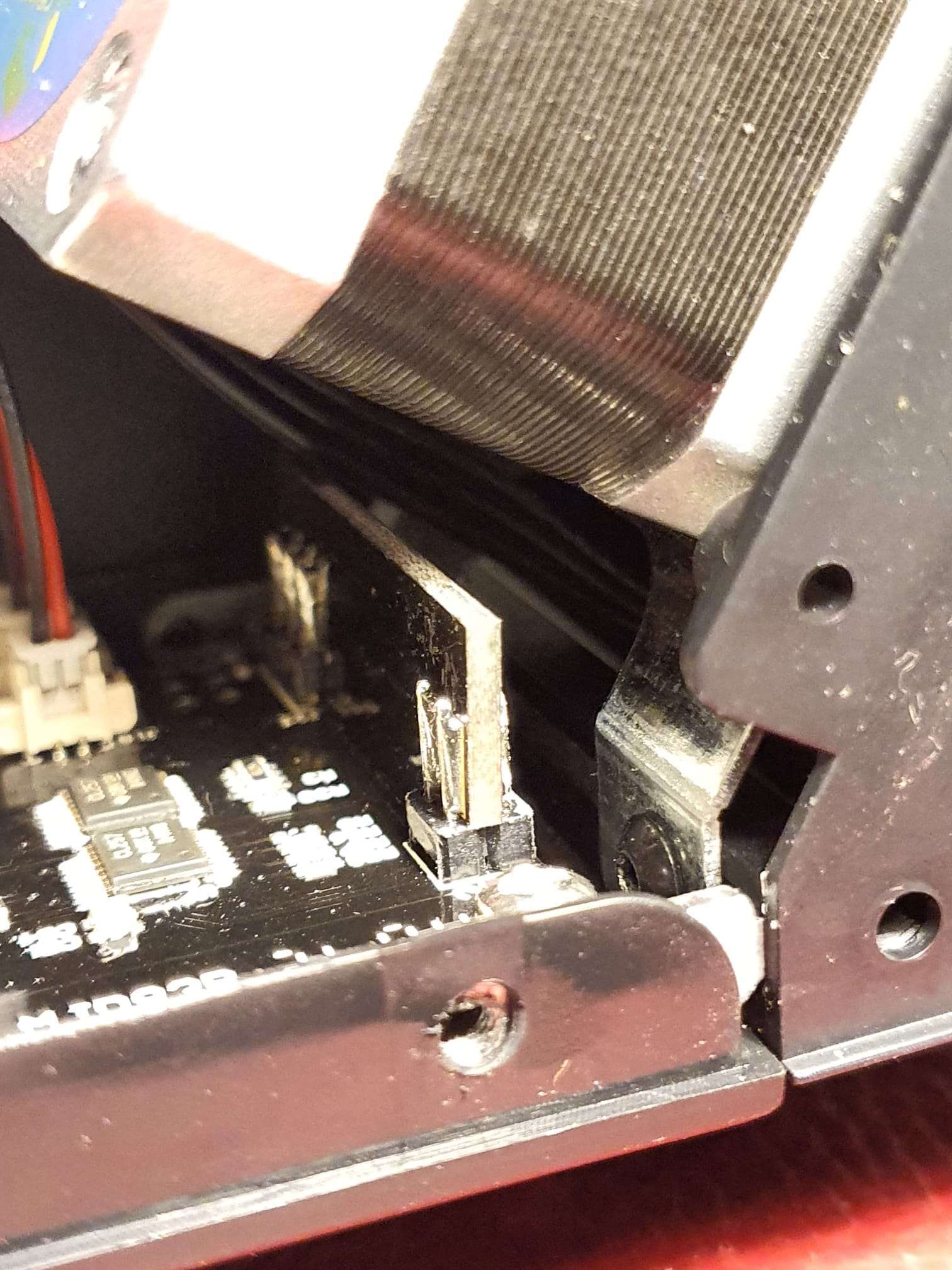
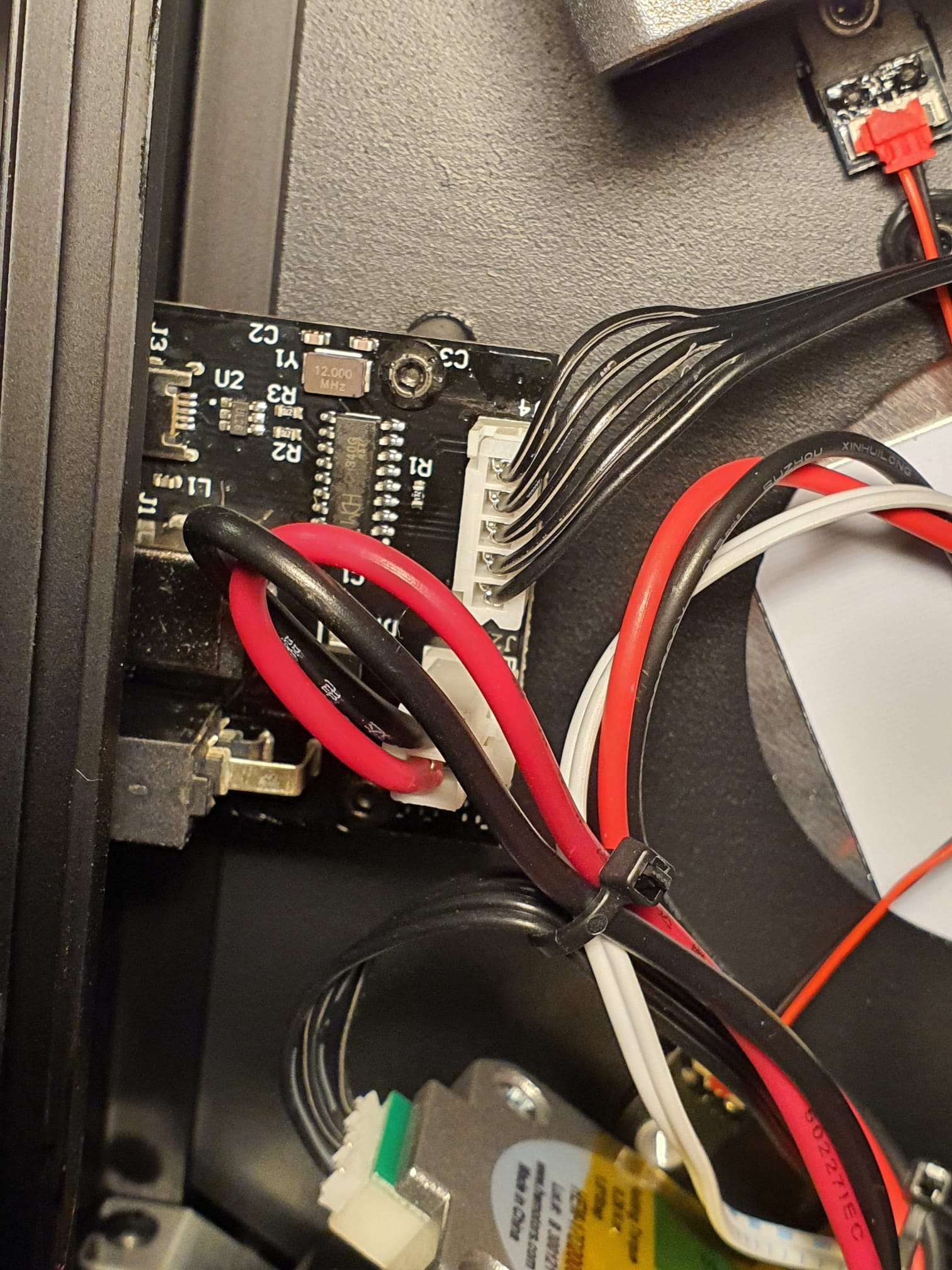
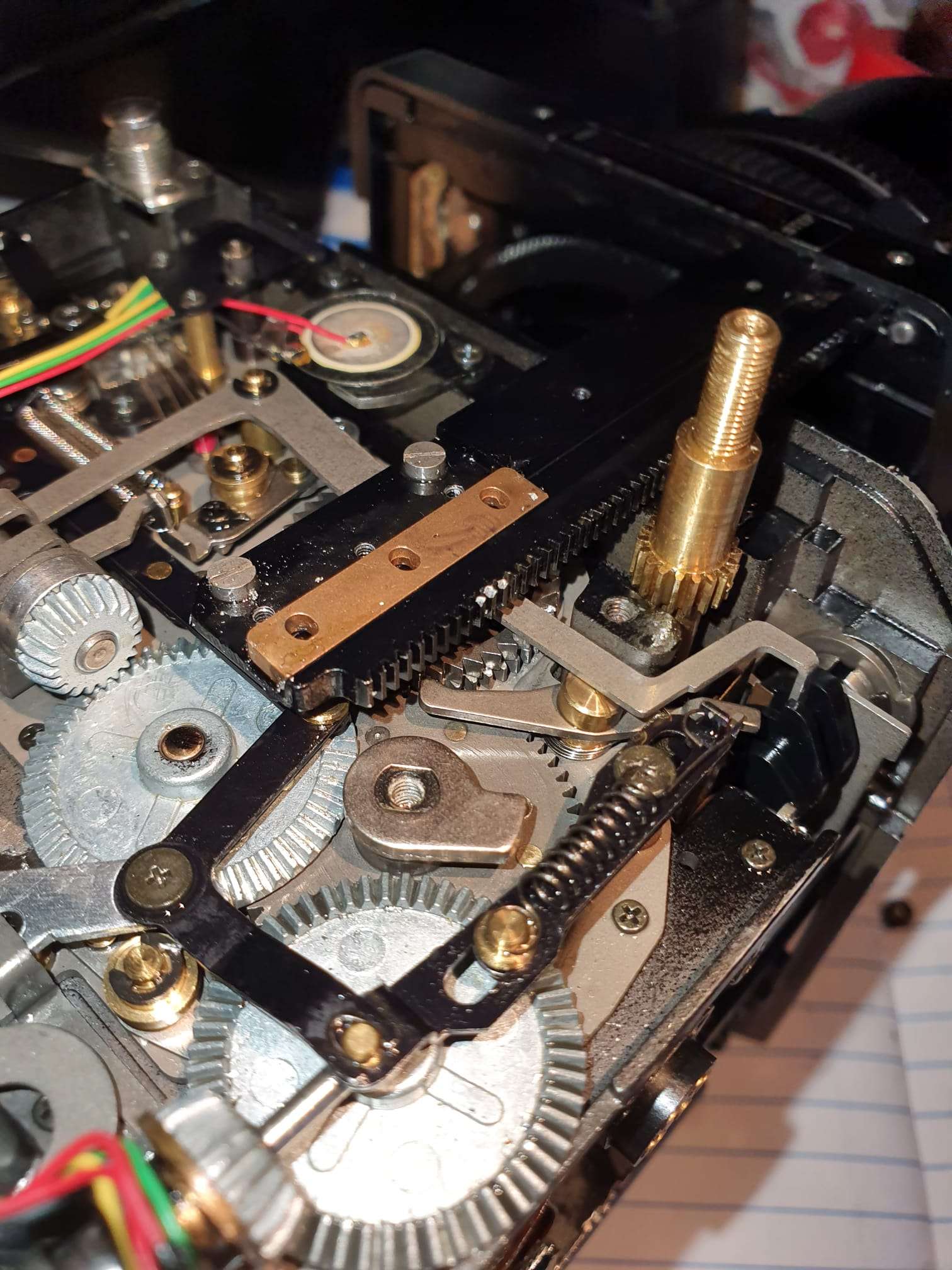
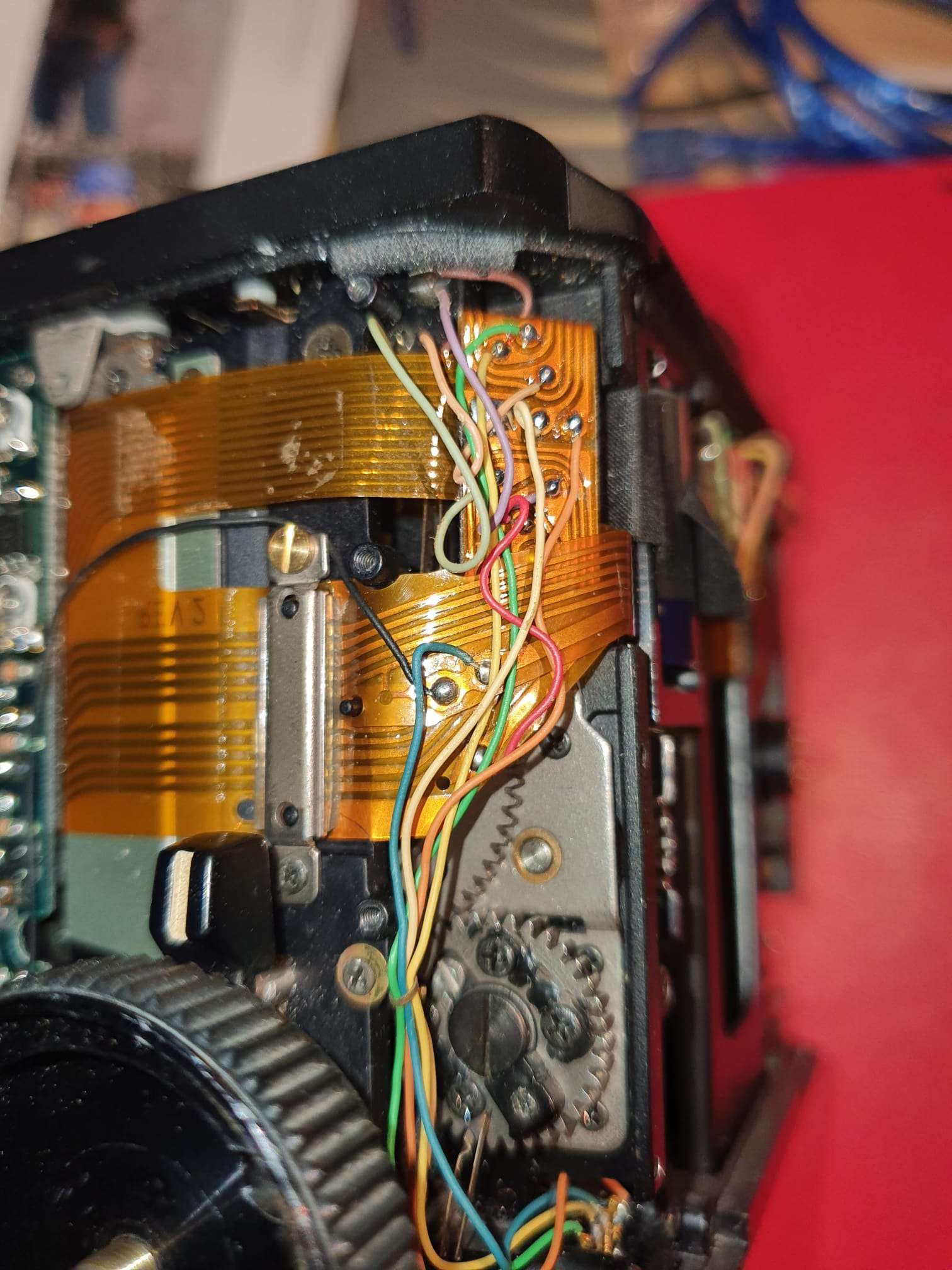
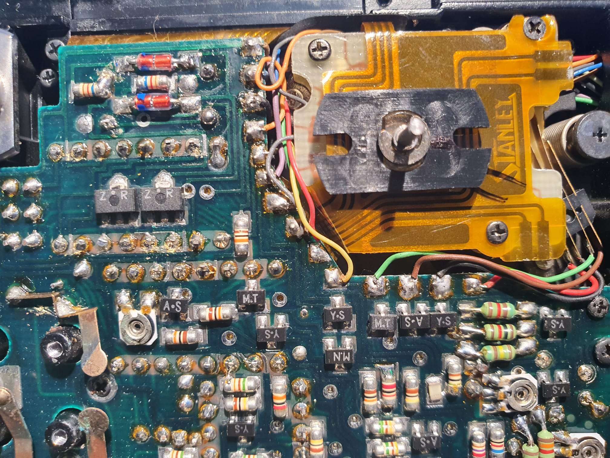
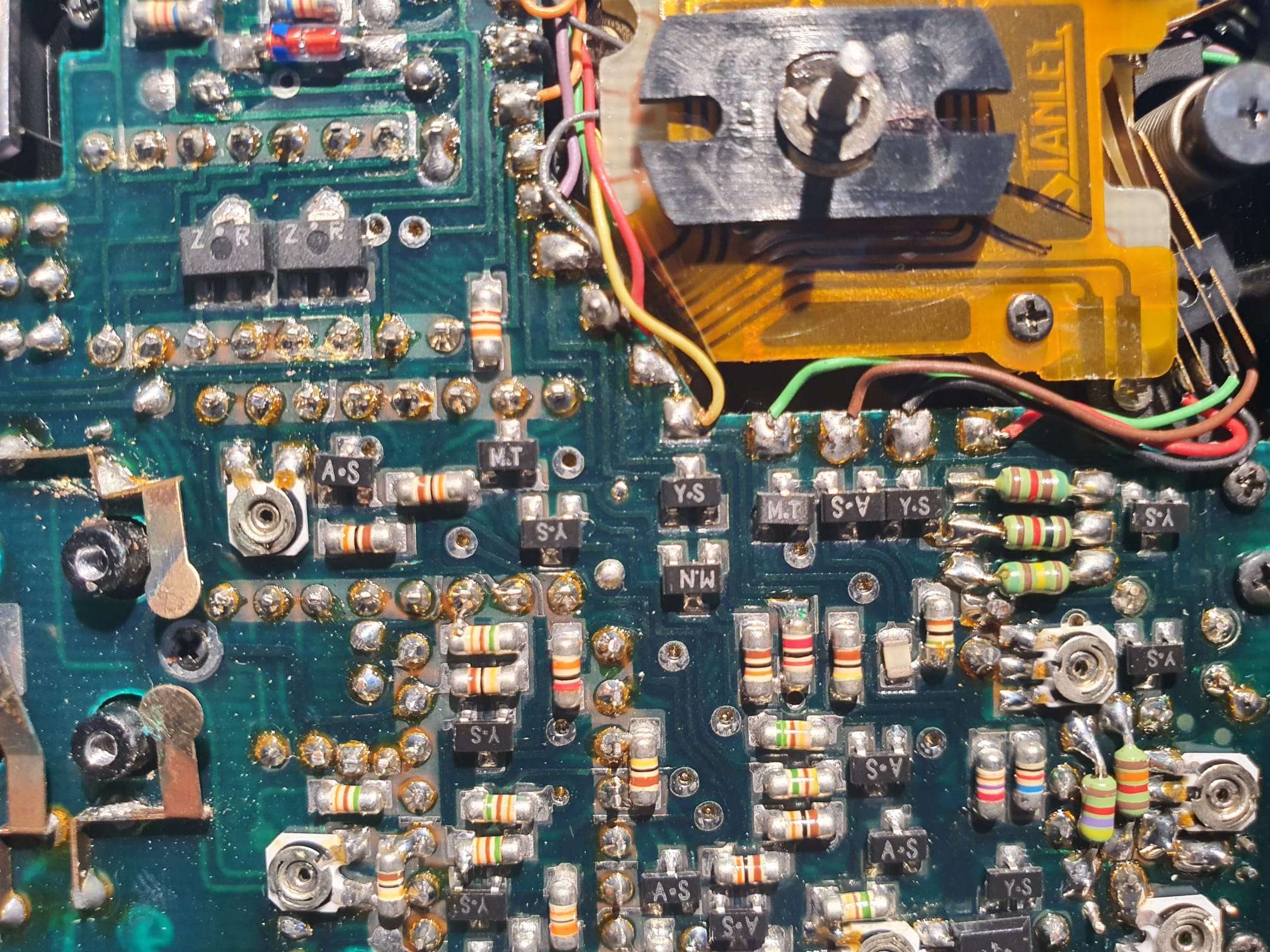
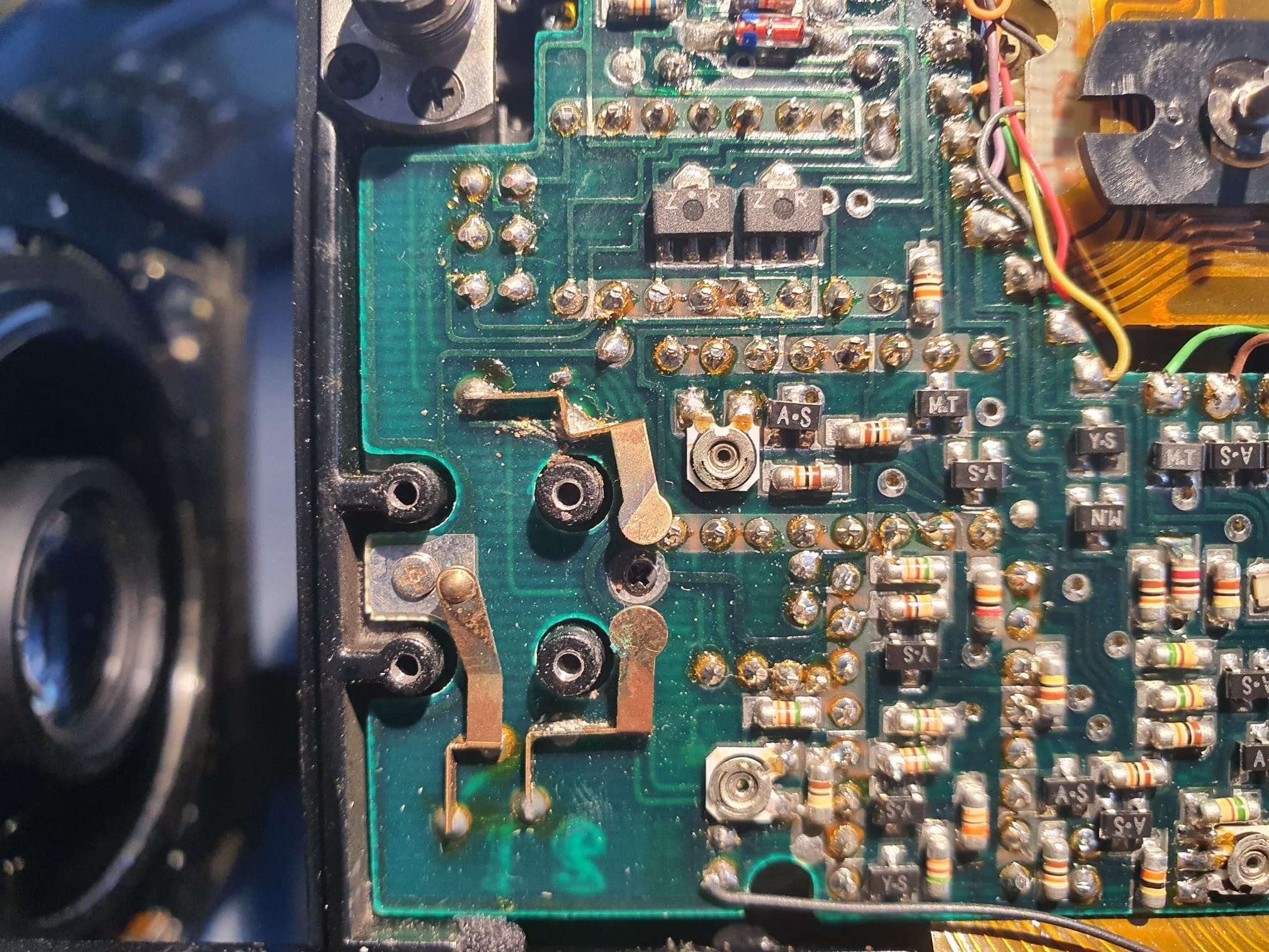
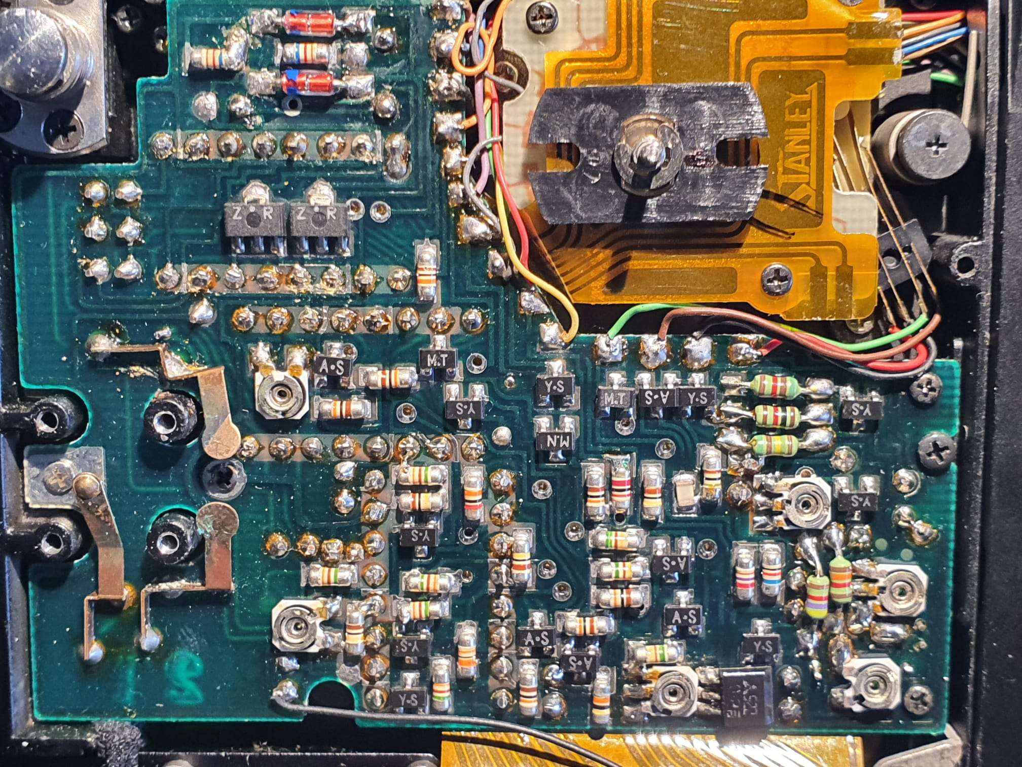
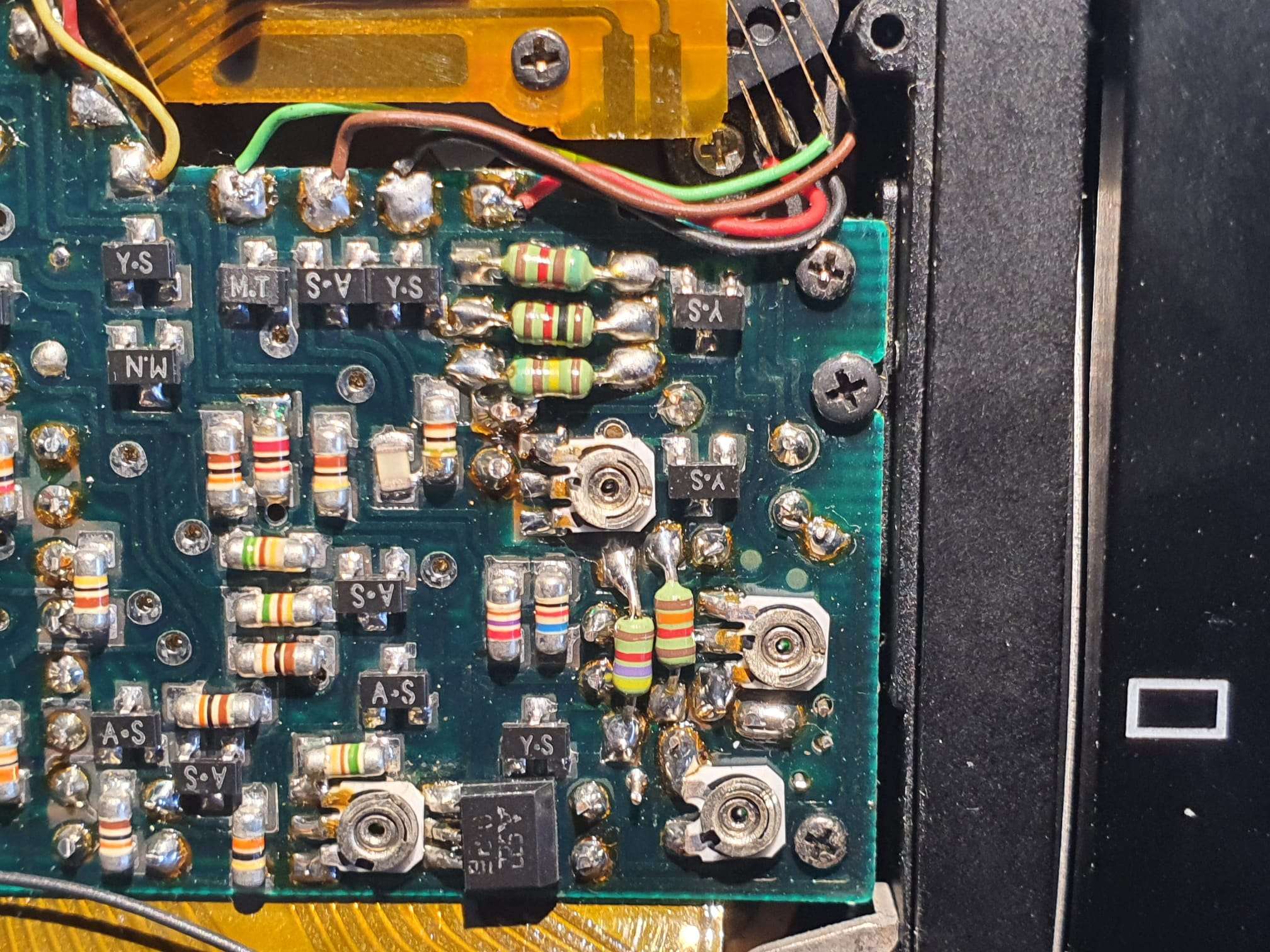
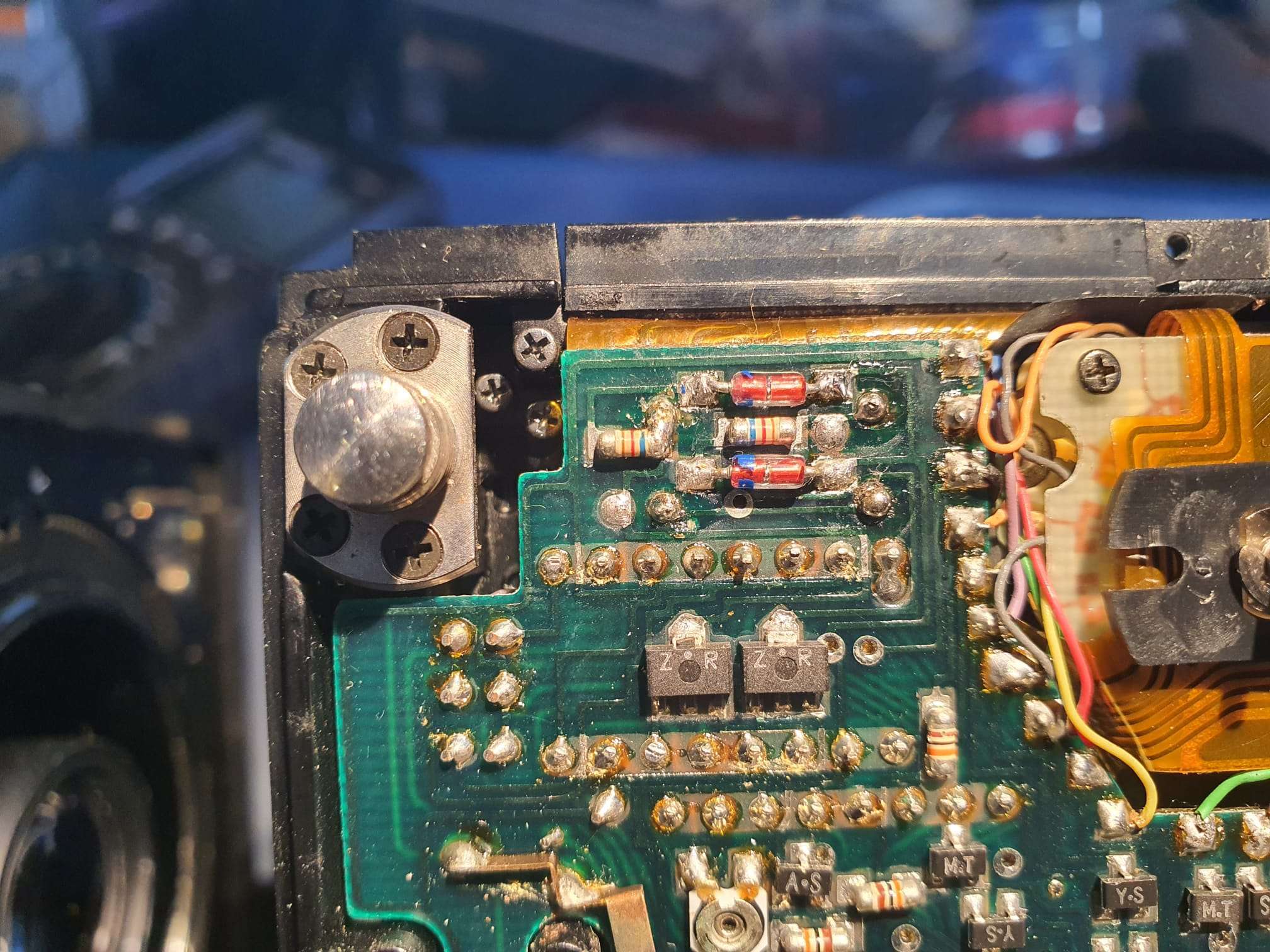
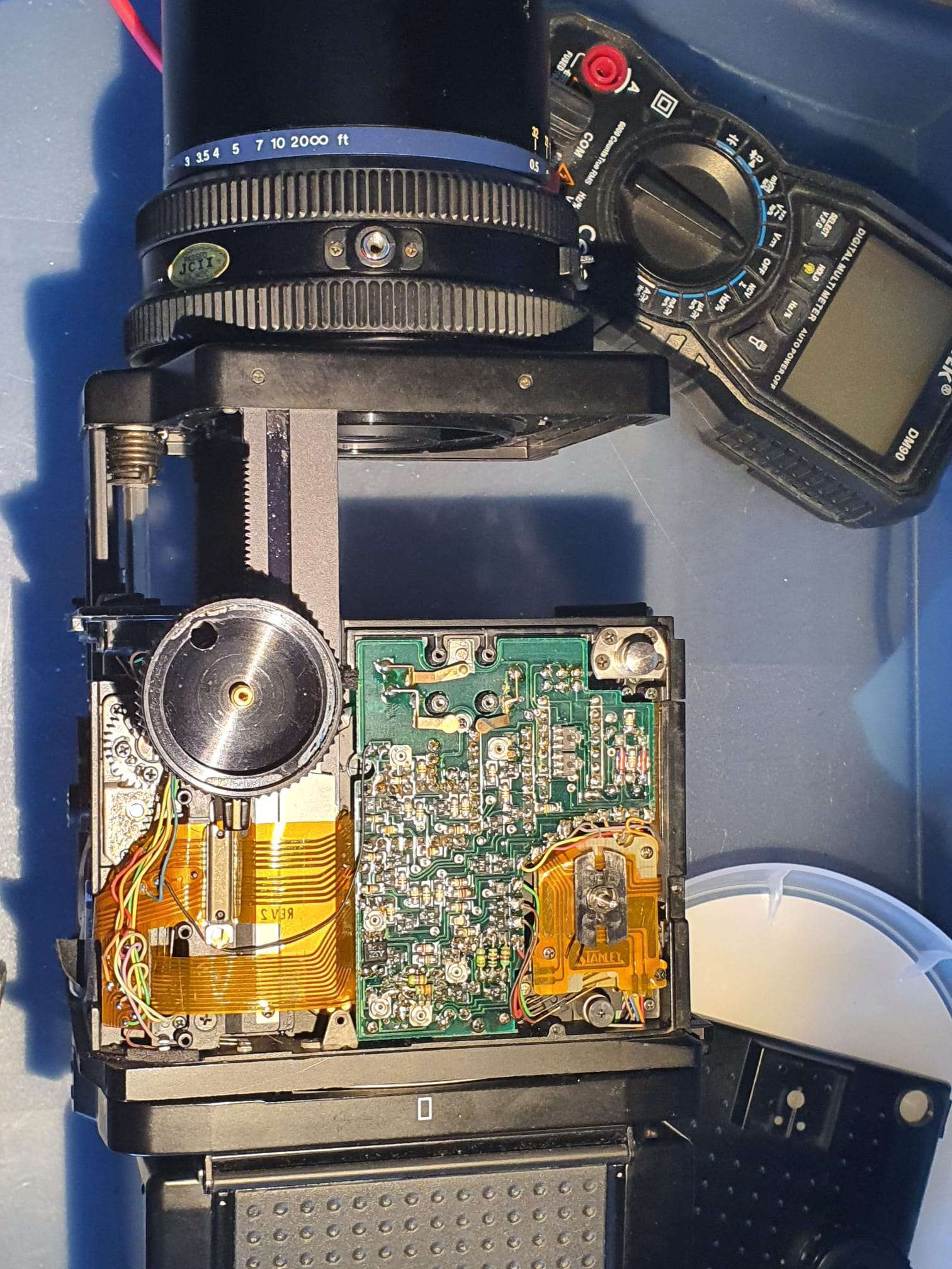
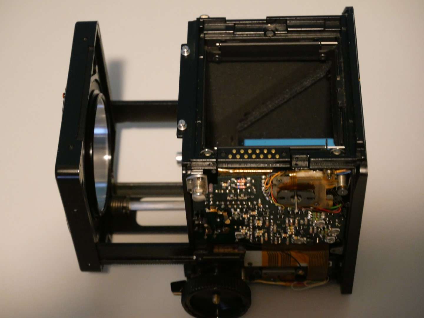
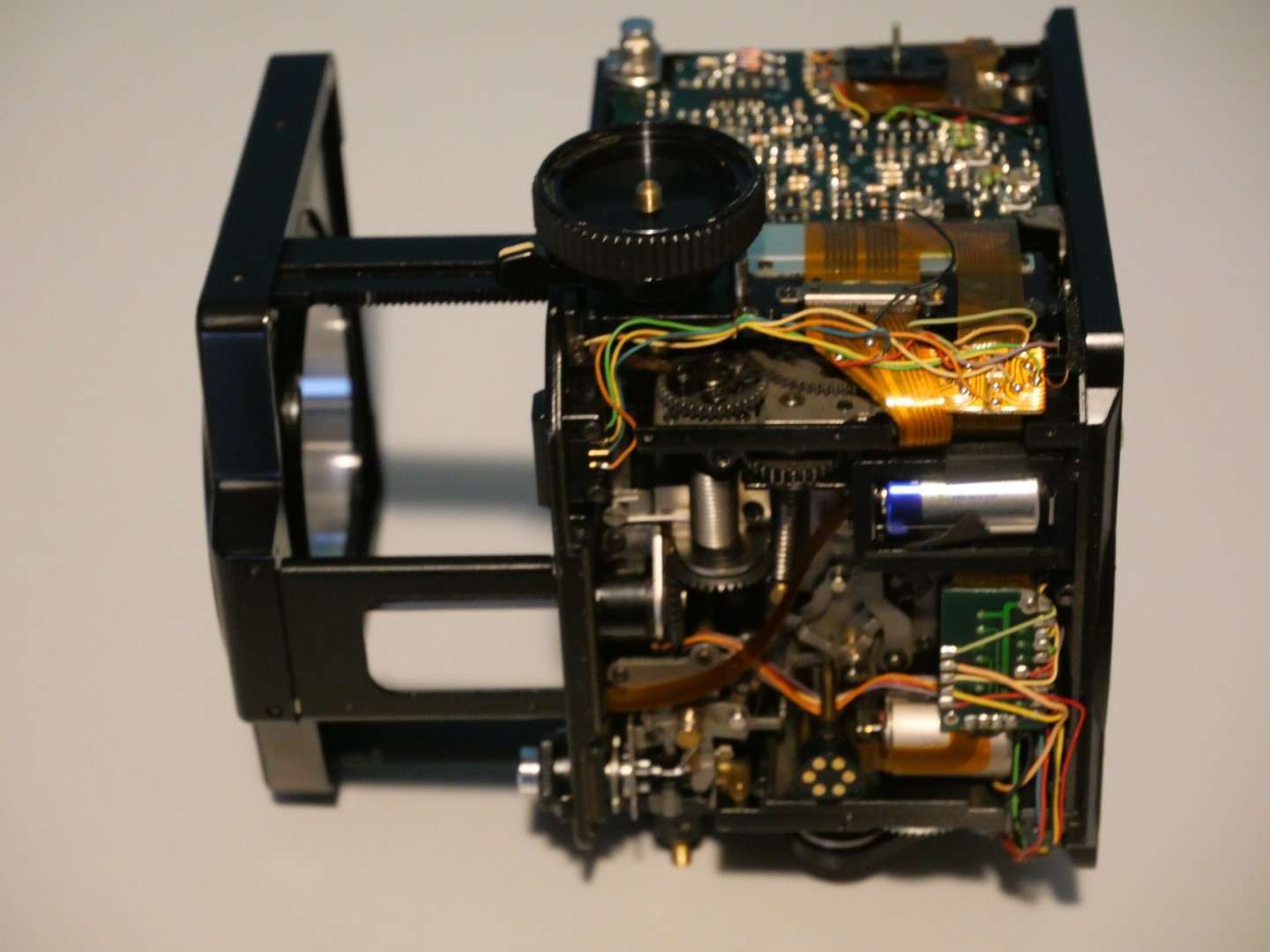
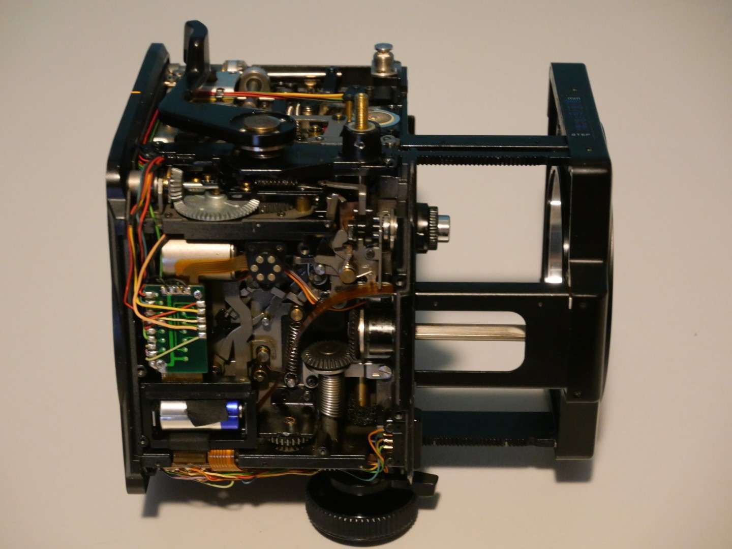
When repairing electronics, I always make a lot of picture up front. This helps especially with identifying the small components, both for the function as well for their specific value/type.
What makes this repair more difficult is the fact that, although I do have the repair manual, no schematics of the working of the electronics is available.
This means that I will have to work with the block schematics and the wiring scheme, only.
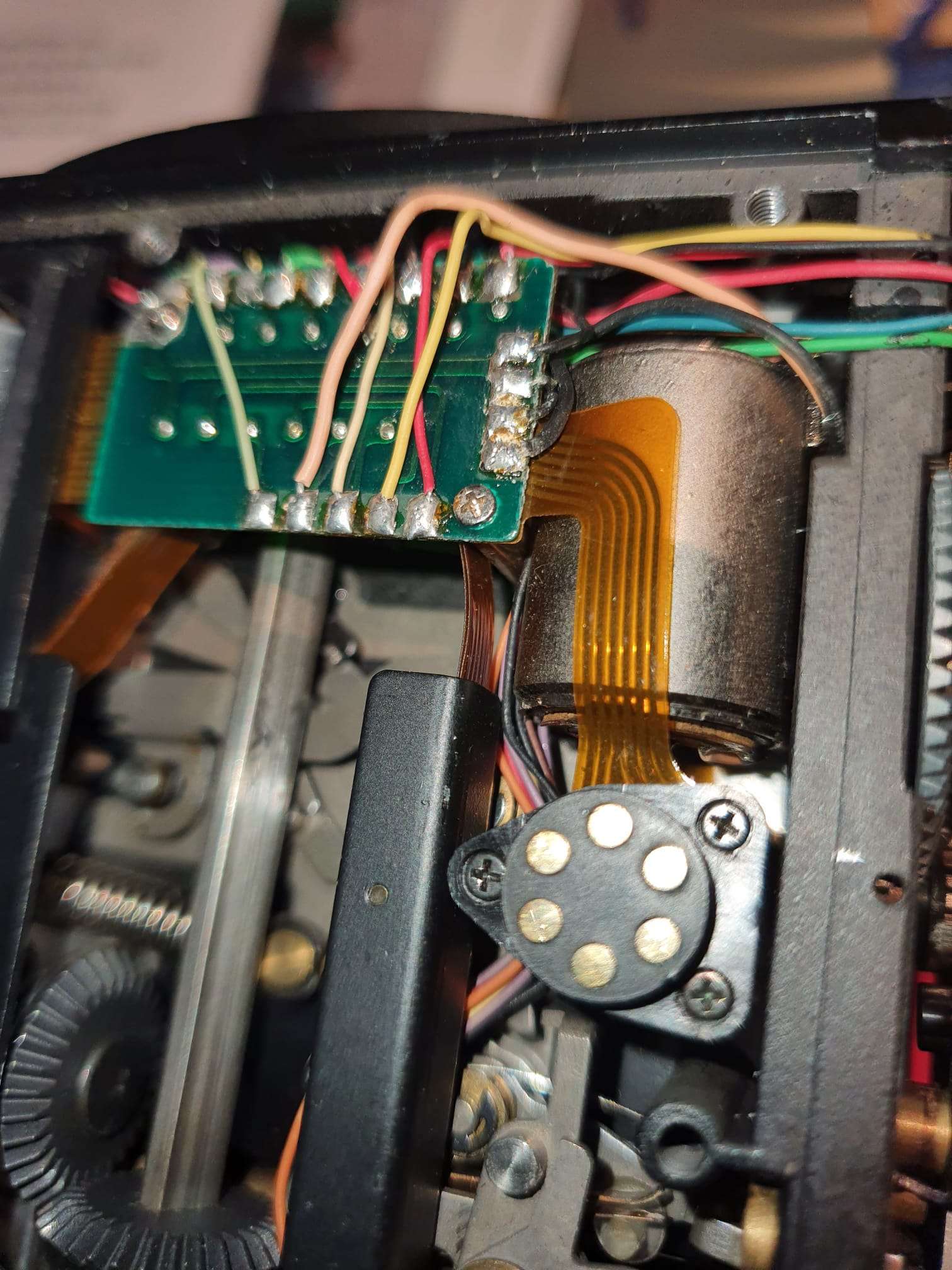
But- a reference is available for all of the voltages versus the pressed buttons at cetera. That will help, of course. And I identified all SMD components, including the transistors. Fortunately, all can still be bought online.
If you look at the added pictures, it appears that this REV2 print and its connected electronics have been upgraded- or repaired- at an earlier stage.
That could mean that this identifies an earlier problem.
First, I checked all reference voltages related to the camera’s settings and then I identified anything out of the ordinary.
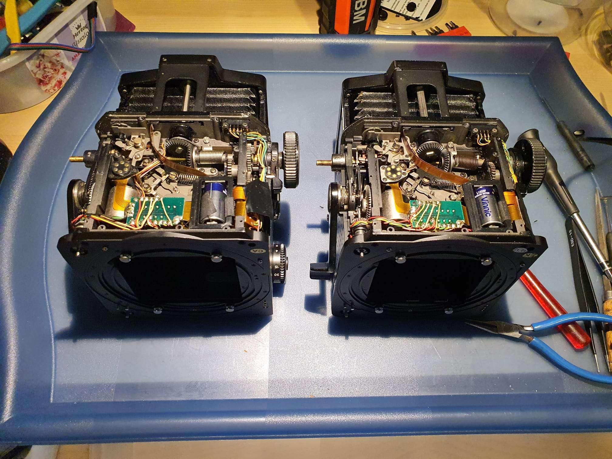
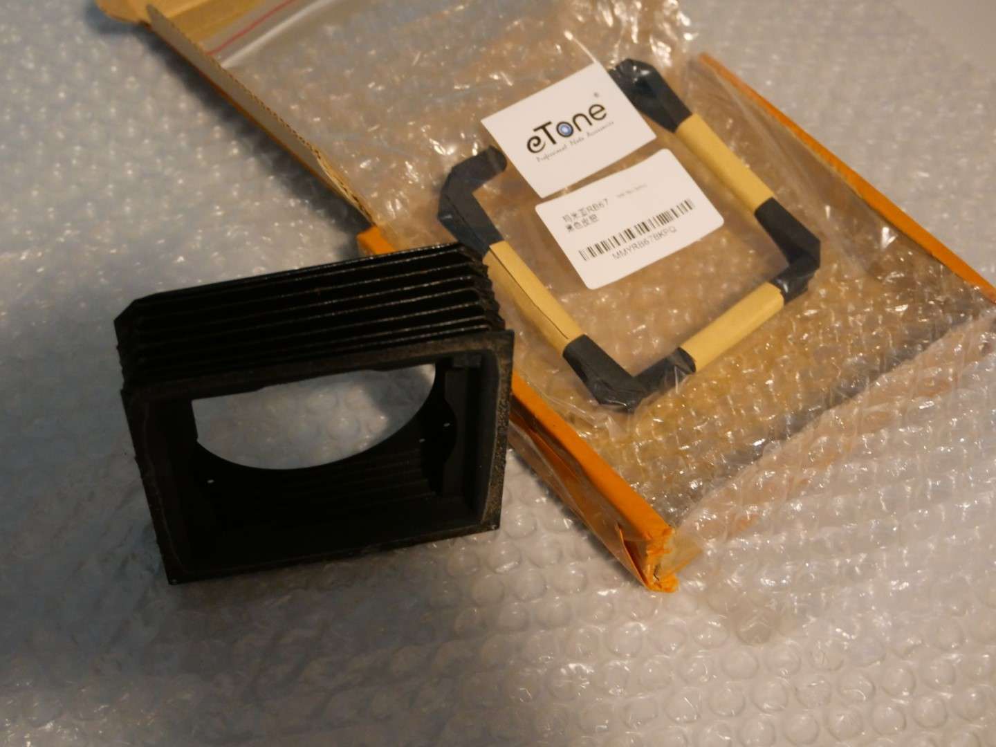
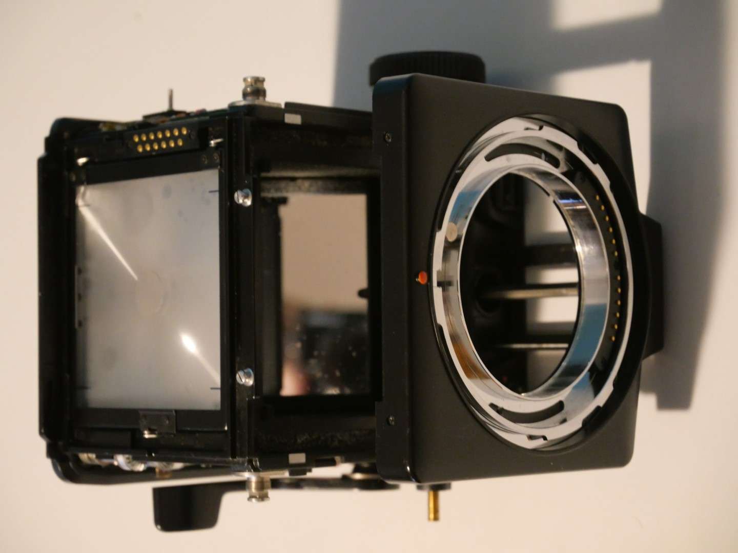
Replacing the bellows of the RZ67 camera can be broken up in two parts:
1) The actual replacing as taking it out and in again, where the steel plates that hold the bellows are taken out and in with the actual bellows attached to this. this procedure is described in the repair manual.n You will need a very long X screwdriver for this, with a small nose. And some patience, good lighting and (in my case) additional glasses. And- if you replace the internal cloth part of the bellows: You will require some special light-blocking foam when mounting the bellows back in again.
2)The more complex replacement is taking the in-between cloth part of the bellows off the steel plating and replacing this with a new bellows unit, as you can buy on ebay/ aliexpress et cetera. That’s what I will describe and show you in this post.
Steps to take:
Remove the cloth from upper-and lower part with use of dessicant, and tricloorethane or any other solvent that does not affect the paint on the steel plating. ‘debonding might do the trick here.
Clean the steel plating.
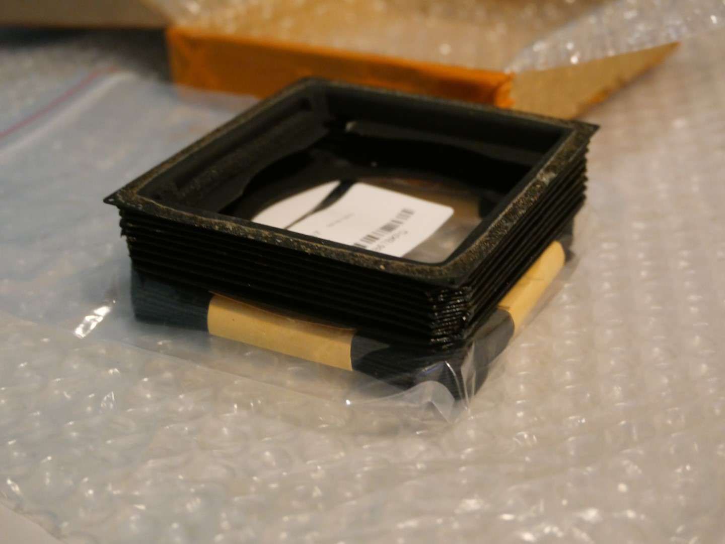
Test-fit the new bellows on the steel plates;
put some glue on the rear steel plate, where the connection was in the old situation.
Put the bellows on the glued plate and use a brush with a bit of glue to attach the bellows to the steel plate.
Let it dry.
Do the same for the other steel plate.
Let it all dry.
Mount some foam as lightshield on the connecting part of the steel plates
First, mount the bellow to the camera’s largest part with the 4 screw in the corners( only 4 screws on this side!)
Then, extend the front to maximum and screw the bellows with the 9 screws to the front, through the camera’s inside. Just screw the screws in a little bit, do not yet tighten. First do 3 or 4 on the outside, then the rest. After the last is in, tighten them all.
You’re done!
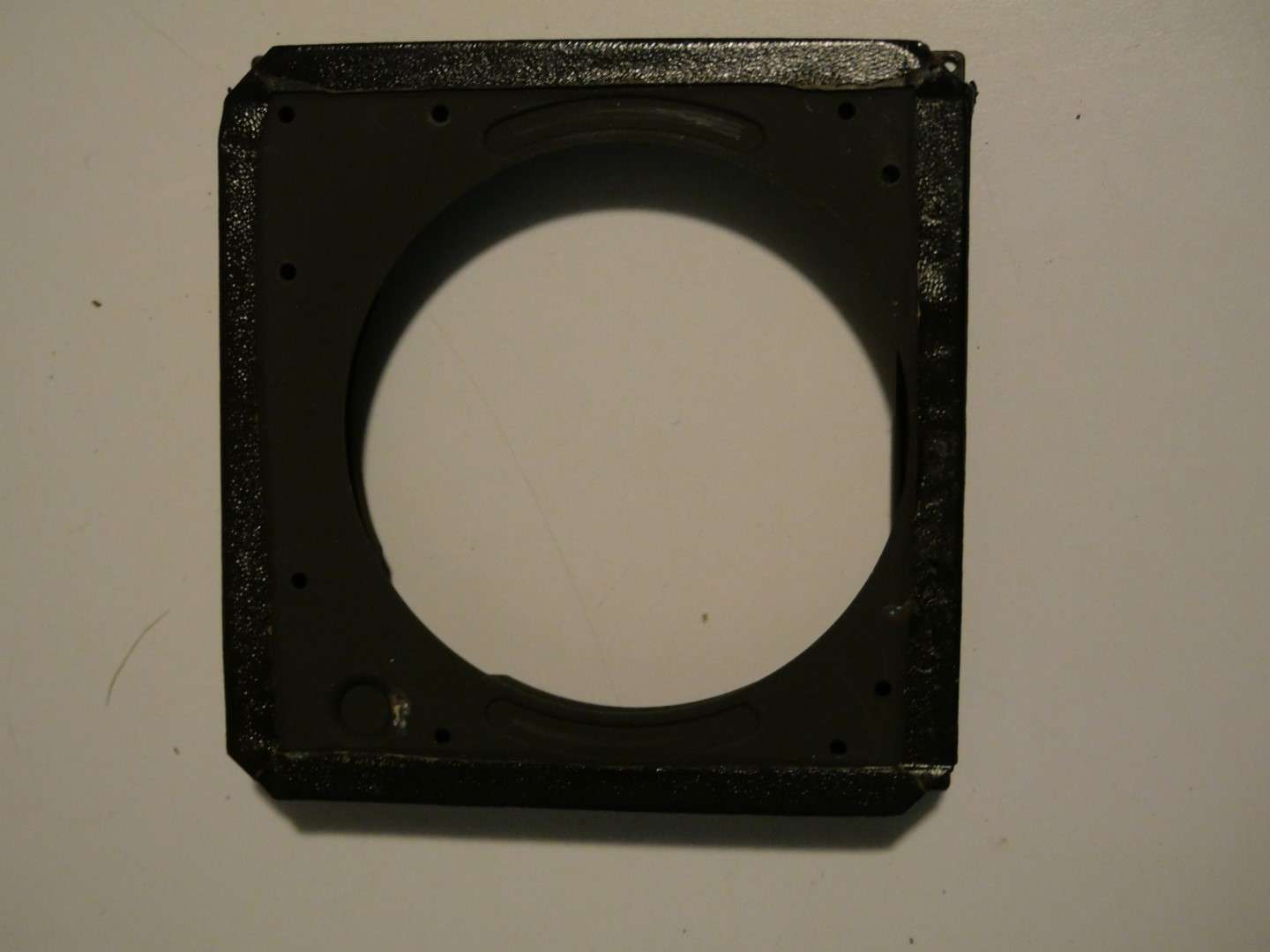
After the new bellows is glued on the steel frame, part 1 will be done.
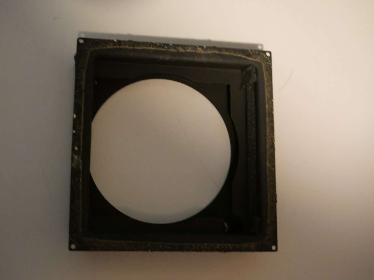
Now there is just a gap in the camera where the bellows used to be:
My Mamiya RZ67 Professional received a digital back recently.
After a long search, I decided to get a V-mount digital back (originally for Hasselblad, old version cameras) version since an original Mamiya adapter plate to a Mamiya 645 mount is extremely expensive.
And an adapter for or a Hasselblad more poular H-mount is not very well supported, electrically. I know that shutter release will work BUT the Phase One adapter plate that connects the Mamiya RZ67 Phase 1 Professional to the V-mount digital back is around 300 US Dollars and was available on eBay .
This is the adapter plate I bought between my RZ67Pro I and the V-mount digital back Aptus leaf P65
It took me some time to get everything working, since I did not have a P-P cable to connect the 2.5mm entry of the digital back to the shutter contact on the camera or lens. This is required to get the digital back triggered at the moment that the shutter opens.
The setup looks like this:
The aptus65 works with standard samsung batteries of which I ordered a couple of the largest possible.
I also bought me a 64GB Compact Flash card, which works much better than the CF to SD adapter I used before.
Getting the pictures onto my PC works easy: put the card in the CF reader , copy the files. Then the tricky part begins: You must transform the imported files with a decoding program that is fortunately downloadable on the mamiya leaf website, but it is a bit hard to find.
Then, import the required app for windows to edit the .MOS files in the regular image viewer, save a copy as jpg and you’re done.
It is also possible to use lightroom, or any other good imaging software package.
I also have a firewire cable setup that I used before for my digital8 camera’s. This also works for the Aptus65, but I don’t expect to ever use this.
Firewire is btw the only way to power the Aptus65, if you don’t wanna use the batteries. But you will need a very good power source on the USB-C connector to get this to work.
The images are very good, as to be expected. the 28Mpix sensor is more tha adequate to get good results. BUT it is a pity that the sensor is only 44×33 mm while the POV of theRZ67 is 7×6 cm. This also means that you get only half the image (more or less) of what you see in the viewfinders’s image.
I printed a mask for the viewfinder at a crop of 1.3 vs. a 645’s normal view so the view resembles the taken pictures
That is exactly what is needed here, since the Aptus leaf65 has a crop of 1.3 when it would be used on a 645DF camera (which this V-mount version cannot, obviously do) with an (almost) 60x45mm medium format.
Which in fact is quite a bit less (53.7×40.2) in real image size, see the below table.
44×33 relates to 53.7×40.2 as a crop of 1.3, as the seller states in the folder of the Aptus 65.
Negatives: Well, the rotating back does not work with the Phase One adapter plate, of course. And I still have some cleaning to do on most of my lenses before I attempt to do any serious shooting outside. And the entire setup gets quite heavy for outside use.
Positives: It helps me a lot to work and learn with the RZ67, using the digital back. I can shoot and shoot on, experimenting with light settings, flash, counterlights and so on without destroying any real film.
My intent is, though, to use the RZ67 with normal film and the full 7×6 capabilities.
And use it for architecture, mostly in Amsterdam.
I already have quite a lot of pictures, taken with my Sony A77RII &35 mm pro-lens and with my old Panasonic dual GX8 setup, but I am very much looking forward to get some great shots with the RX67 on large(r) format film in B&W!
[Update 2022-07-14: I got my Creality lizard today !
Extremely small and fast, I just tested it this afternoon and it is way faster and easier to use than the Creality CR-1!
More to follow soon, in a seperate post.]
Comparison of 3d-DIY hobby scanners versus Creality CR-1 3d scanner
Previously I built and extensively tested both versions of the Openscan scanners and the ciclop scanner. The openscan types are very different from each other but use simple firmware with an Arduino or a Raspberry PI contoller. The Ciclop is a simple 3d scanner with a rotating platform and a USB camera.
Openscan mini
The Openscan mini takes pictures with the RPI camera and rotates the camera around the object to be scanned. This indicates the limitation, you can only scan small objects. After scanning you have to import the photos into meshmaker or via the new free cloud solution from Openscan’s developer Thomas Megel. The mini is fully controllable via the web-based software available for download on Thomas Megel’s website, where you can also use it to upload and process your photos and then download the 3d files.
Openscan mini + Raspberry PI (2-4)
Openscan classic
The classic version of the Openscan scanner can handle larger objects and uses an external camera. I used my Canon 5D Mark2 for this, with a ring flash. This solution works pretty well and uses the same software as the mini for processing and rendering. In the separate Arduino unit that controls the rotors of the scanners you can set the number of steps vertically and horizontally and you have to transfer the pictures from the camera yourself to a meshmaker-like processing to construct a 3d image. Quite cumbersome but it can be done for free and gives a pretty good workable result. Provided you spend some time on it.
Openscan classic 3d scanner with on the left the Arduino controller, with small buttons you can set the steps and on the LCD you can see what you are setting. Below is the connection for the remote to your camera. It is recommended to use a good flash or at least extra lighting. The advantage of an external camera is that you can make razor sharp images, for example by using follow focus or, as I did on my Canon5DII, using continuous focus.
Ciclop 3d scanner
The ciclop scanner works with a fixed platform and no vertical movement. It is very similar in operation to the Creality CR-1 scanner but I have never had good results with it. There are 2 red diode lasers on the sides and 1 USB camera in the middle. The result in terms of photos is fine, but it is ultimately about the rendering software and the processing of the photos taken, just like with the Openscan classis. and that is for the hobby environment just in my experience not (yet) sufficiently well developed with this ciclop 3d scanner.
The Creality CR-1
I purchased the Creality CR-1 scanner in late 2021 because I saw a few projects coming up where a good scanner would come in handy, and I didn’t want to spend extra time on it. Besides, I was very curious about the results of this ‘all-in one’ scanning solution.
The scans made are very useful, and the rotating plate on which you can place the object also works well.
My experience is that hand scanning is very laborious, and you have to scan all parts of the object to be scanned carefully. This means that you have to pay attention both to what you are scanning through the screen, where you can follow the construction of your scan live, and what you are doing towards the object with the scanner in your hand. That takes some getting used to, but after a few scans it is much easier.
Very nice is the way it works with this scanner: The live-view of the accumulated scan tells you where you need to scan even better and if you forgot something you scan again and let the included stitch software make one merged scan of it. That also works very well.
What do you need besides the scanner: Saving the data is done on your PC or laptop, rendering is done via a GPU, and the control and power for rotating table and the scanner itself is done with a separate PSU.
It helps when you have a fast GPU with quite a bit of memory. I have a 3600 GPU in a Thunderbolt3 external casing attached to my Dell XPS13 i7 for on-the-go use with 5 meter extension cords for the scanner. This works very well, but really the 13 inch screen is too small for this work. Carrying an external screen is not an option so I have to make do with this. And the external Thunderbolt casing is actually too big to carry as well.
Another possibility would be to use a gaming laptop that already has a fast GPU in it, with a 17-inch screen. Might get one anyway, when more work on the go comes along. For now, I mainly use the scanners at home/business so I just use my hi-res 27 inch IIyama screen to the Thunderbolt / 3600 GPU, that works fine!
Experiences: This scanner works completely differently than the Openscan versions. The camera needs more distance from the object to be scanned and therefore the whole setup requires more space. I had to get very used to the fact that you have to have more than a meter all around to get a good view of your object, even with small objects.
I am still going to try using a front lens or zoom lens, need to check what fitting this scanner uses for the lens-to-sensor.
Summary and overall rating from 1-10:
The Openscan mini (7) works fine for small objects, is easy and good to use with the web-based software and with the online rendering service.
The openscan classic (6) works well but requires a relative amount of setup work, knowledge of and experience with the setup an you can use the same online rendering service from Thomas Megel.
The Ciclop (3) is in my opinion too immature to use seriously.
The Creality-CR1 (8) is a valuable professional solution for medium size projects up to large projects (10-200cm diameter), good local interface via PC/Laptop with fast processor and fast modern GPU.
In the Netherlands, City councils usually forbid to put charging cables for electric vehicles on public pavements.
And- to charge your electric car, of course you want to use your solar panels and connect your EV directly to your own domestic power grid.
But what do you do when your municipality forbids you to lay the charging cable across the sidewalk to your car?
My municipality has passed a council resolution whereby you can order a charging station through an external party, and so then you can have a public charging station installed nearby. Provided there isn’t already a charging point within a reasonable distance. In my neighborhood there are hardly any charging points, and the only one I have been able to find niche about 400 meters away, consisting of 2 AC charging points where two cars are always charging.
In my search for possible solutions to still make it possible to get to the car via the public sidewalk so that I do get to charge the car at home, I have come across several solutions. Of those solutions, only one is really useful, because all solutions with cable trays or cable protection over the sidewalk can still lead to liability issues if someone trips over the cable or is otherwise inconvenienced by the cable over the sidewalk.
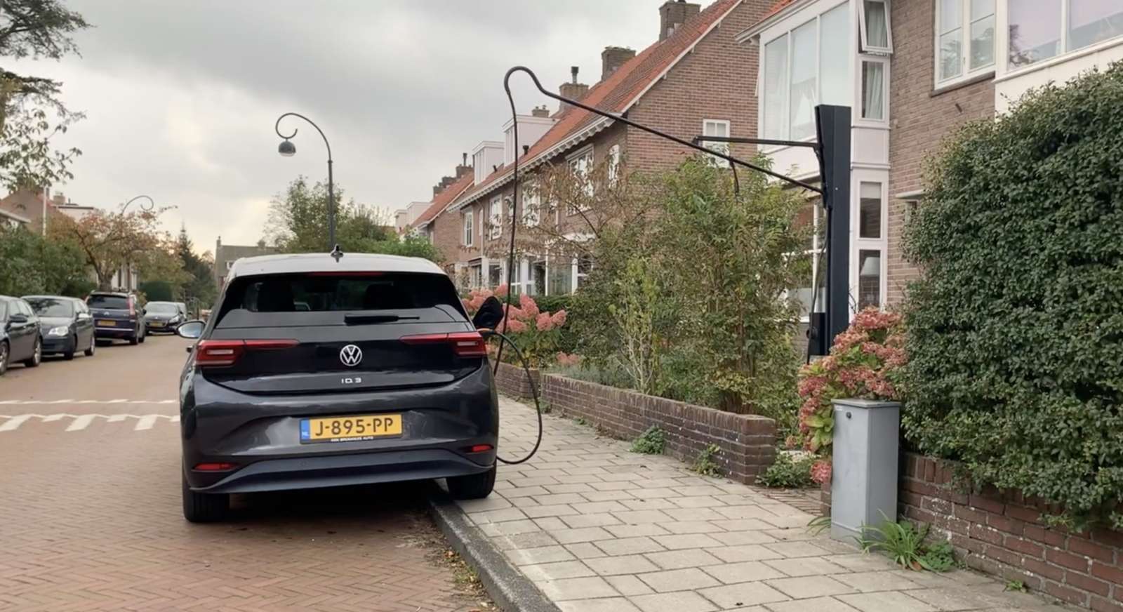
The solution of using a hinged cable tree placed high on your facade to get the cable across the public sidewalk directly to your car is a pretty eye-catching solution. But- the sidewalk remains free of obstacles and no one is bothered by it. Except perhaps for the fact that it doesn’t look very pretty. I wonder how the municipality would want to and can- prevent this solution. After all, similar things like flags on the public sidewalk at a sufficient height are not enforced either. If that is even possible by law.
In terms of principle, it looks like this:
The lever can be moved upwards after use. Then the whole tree falls away into the vertical holder. Very nice, just a pity that the link to the supplier doesn’t seem to work anymore.
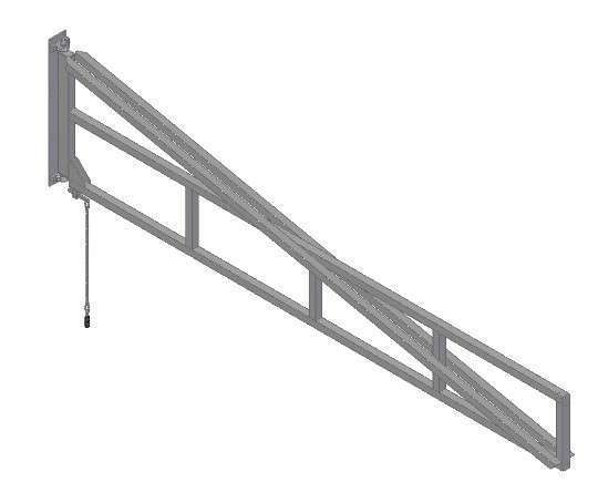
For my home situation, I prefer to place the lever on the facade. With a hinge point, the lever can then be moved away nicely against the facade after use, where you can attach the lever.
Below is an example of a company that makes these levers for hanging welding shields in factory halls. They also exist in extendable versions up to a length of 6 meters.
When you create such a solution, it must of course comply with all the rules and regulations, and the design must be such that it fits in with the surroundings. The choice of color and material is also a matter of concern, and it must not cause any inconvenience, such as clattering against the facade, etc. And the structure must be professionally grounded.
I do expect resistance from the local authority because they assume that electric vehicles are still in the minority and that there is therefore no need for a serious solution for home charging in public parking spaces.
The world is changing so fast towards electric personal transport, the sale of new cars already consists for 10% of electric cars. Of course the subsidy schemes help with this too, but all those cars sold are just going to drive and need charging spots.
Given the fact that people that already installed solar panels at their home are also the first people to drive electric cars, these people also want to use their installed solar panels for their electric transport. And as long as the net metering regulation for the return of energy is still in force in the Netherlands, the pressure on necessarily wanting to charge the electric car at home will not be very great. But with the rising energy prices suddenly making public charging much more expensive than charging at home, the pressure on wanting to charge at home using one’s own solar panels could become much greater.
VEHICLE TO LOAD
In addition, the latest development to run your home on your car battery is suddenly serious, because all brands now supply electric cars with a vehicle to load connection, which means that you can also use your charging cable to feed energy back into your home. This means that during the day you can charge your car from your solar panels and in the evening you can use the energy from your car battery. An average family consumes 8kWh in the evening and the car usually has about 50-70 kWh available. Most private solar panel installations start at 8 panels and that is exactly enough to fully recharge the car for the use of 8kWh per day on an average day during the 8 so-called sunny months of the year. And the months of November through February? You will still have to ‘buy’ electric energy during these 4 months. Preferably with wind energy from a green supplier, of course. When you drive your electric car to and from work every day, recharging your EV from your solar panels for those days is obviously not true. But when you regularly work at home, the story does apply for those days, as well as the periods during the weekends when you are plugged in at home.