Web hosting at home with a DS718+ Synology Web server

The performance of my larger sites left a lot to be desired, and the costs are running up considerably.  I had over 10 sites running, all with the same provider and the costs per site vary between 185 Euros per year and 65 Euros per year.  For the large sites I have 5GB storage and the smallest is 200MB.

HOMESERVER: Previously I hosted a few websites from home, on a Zyxel NAS with a cheap domain provider.  That all worked fine then.  Based on my previous experience I have bought a Synology DS718+ web server, a few fast SSDs with mirroring in it and up to RAM.  The cost is about 800 Euro.  As a backup I have a DS218 play with a couple of big harddisks in it and extra RAM as a normal local NAS with an extra mirrored wordpress server for emergencies and maintenance on the main server.

So now you see this post from my home server.

My experience is that it is always better to be the only one on your own web server than to rent shared hosting, regardless of the so-called SSD hosting et cetera.  That’s what larger companies do as well: Just a fat server on a fast internet connection.

Just to be sure, I do have a backup (UPS) with battery for the 230 Volt power to the internet modem/router and web servers, and a data connection backup via a mobile connection, in case the internet connection goes down. The autonomy of the UPS is about 6 hours.


And… whether I like it?  Actually, I’m mostly very happy with the merging of my various sites into 1 overall site because of its clarity.  Because of my diversity of interests I had just too many sites running which resulted in insufficient attention on the sites.  Now that I only have one for my hobbies and one for my business everything has become much simpler.

And how to proceed? I will cancel my webhosting and I have to see which domains I want to keep.  That also depends a bit on the costs.  If only the costs of the domains are not too high, I can keep 6 or so. Which I then redirect (fixed, 302) to my home server.  Eventually only 1 domain will remain, but which one should that be…?  And then I can make my URL unambiguous again!

That’s it!

Traction avant 1955 big trunk conversion to wheel

Recently (9-2021) I was able to buy me a tailgate and wheel cover from a wheeled TA version.  This was the start of my project to convert my 1955 Citroën Traction Avant into a wheeled version.

It’s a matter of taste of course, and I just think a wheeled version is much nicer than such an imposed trunk.

Below you can see what my car would look like with a wheel instead of a trunk:

And, for comparison what my car looks like BEFORE the conversion to wheel:

Picture  dates from 2007

The trunk hangs from the part of the body directly under the rear window.

On a wheel version, there is still a section of sheet metal under the “kink” in the sheet metal that is under the window.  That is completely missing from the trunk model.

And the underside in terms of sheet metal runs all the way through (gray) , including under the trunk lid (gray lid with black wheel cover).  This should be constructed anyway, and connected to the existing trunk floor plate. Everything under and behind it has to be removed so also the spare wheel well and the existing extra extension of bumper brackets and the ‘standard’ extra bolted-on sheet metal.

The fender points L and R are connected with a piece of sheet metal, under the fixed body (grey). This sheet metal part is still readily available as an aftermarket part.

THE APPROACH – is planned for mid 2022, after finishing the ID20 –

LPG tank out, gasoline tank out from under it.

OUTSIDE THE CAR:

First, a fender edge is made that follows the exact shape of the trunk lid of the wheeled version.   Then a sheet metal edge is made that fits in the hole created when removing the existing boot lid.  After that, it’s going to be a lot of fitting and measuring.  Temporarily the new sheet metal part with sheet metal edge for the lid is fixed with U-strips instead of the lid.  This makes everything a lot easier to handle.

ON THE CAR:

Next, the new sheet metal part is fixed in place and secured with small MIG dots.
Then mark where the excess material needs to be removed.
Grinding off the new sheet metal, and
everything to size, strip the edges and reposition the new part
Welding the new part in place, measurements and dots.
Weld in the 2nd round of dots.
Then fit the valve.
Mount the valve and fix it (by MIG welding the dots to the edge of the plate).
Then weld the plate to the body with a few spots at a time, and keep cooling with air.
Weld in further and further until everything is welded in, and wait and cool with compressed air.
Then without heating grind flat with flapper wheel and
Then use fiber 2-K waterproof filler to seal the weld and immediate area.
Then bondo over the whole, and
flush with 60 grid.
Filler primer over it,
spray contrast on,
manually level with 200,
then spray again contracts
and flatten with 400 etc.
Remove pinholes and again after
Contrast spray and sand with 800.
Waterproof sanding with 1200 and
then to the painter.

CAUTION to use light gray filler, bondo etc. of the same hue/color, this will save possible misery afterwards when spraying.

DIY windbelt for simple and free energy

A magnet is set into vibration as the wind brings a tightly stretched string or tape into resonance. The magnet is attached to the tape and moves in a coil of copper wire.  The coil is connected to a rectifier and provides energy as the magnet moves back and forth.

That’s the principle of the windbelt.

There have been some initiatives with windbelts around 2010, but you need quite a few of them to make a little energy.  And, of course, it has to be blowing….

Solutions have been made with large numbers of windbelts mounted in windows, in vineyards between fields, and also in areas where there is no electricity at all but the wind does blow.

If you combine a number of windbelts with a solar panel you can make fairly off-grid calls…. -)

Example of a window setup with windbelts:

Example of another DIY kit:

(We can supply this kit on request, we always have 10+ kits on stock)

Other DIY examples:

The theory:

Resonance theory with the famous narrow bridge @ Tacoma narrows that collapsed in 1940 , November 7th, due to the wind :


And another setup of a working windbelt:

Citroen ID/DS 1970 front door repair with new door box inside and outside half door plate DIY with description and photos

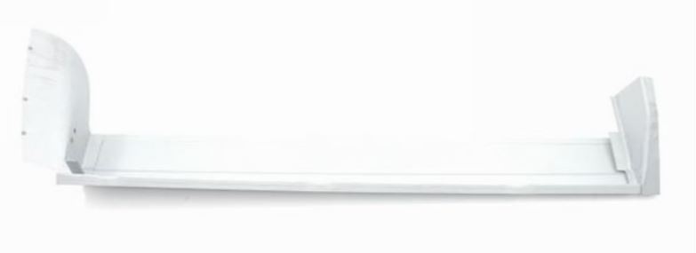
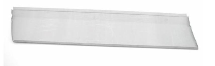
2021-09-24: This morning my new sheet metal ordered from Cit’art for the left door of my DIY Citroën ID/DS 1970 convertible was delivered: A half door plate and a 3-piece inner tray.

For my ID Berline, I’ve previously fitted doors with new half outer plates and door trays a few times so by now I know roughly how to go about this.  Because the Citroën ID/DS has not been very dimensionally stable over the years (understatement!), there is one thing you should always remember: Always fit the tray and then the door plate AT THE CAR and don’t make it all pretty on the workbench only to find out later that the door doesn’t fit!

I might be going a bit far as most people assemble the door body on the workbench and then place the half door plate on the car, but I first align the door body properly using the removed plate as a jig and then weld the new door body in place with a few dots.  Then fit it to the car, possibly aligning it with the hinge points attached to door and car so that the top and side top and middle are perfectly between front screen and rear door/ Perfect means here: In the same place as BEFORE this action.

If everything is as desired, also try it on with the door plate.  If something doesn’t fit, measure the difference in height or depth and remove the door.   On the workbench: Loosen the welds where necessary and correct what is needed. Place the door back in the car and repeat previous steps until everything fits perfectly.

Another important tip: The side pieces of the turret can be placed in different ways: On the intermediate plate, under the intermediate plate or partially under and over it.  I now choose to make the side pieces fit exactly to the door and NOT weld any plate at these side pieces on top of each other.  That means you won’t see a transition when you open the door.  I like that better and it gives less chance of rotting in the future between the places where sheet overlaps.  There’s always going to be moisture in between there.  By the way, I did have the half door plate and the tray intermediate piece cross over where these plates are welded to the old door.  This also has to do with sturdiness, but it is also almost impossible to finish neatly when you don’t want the overlap.  Moreover, you can easily seal this overlap with special seam sealer.

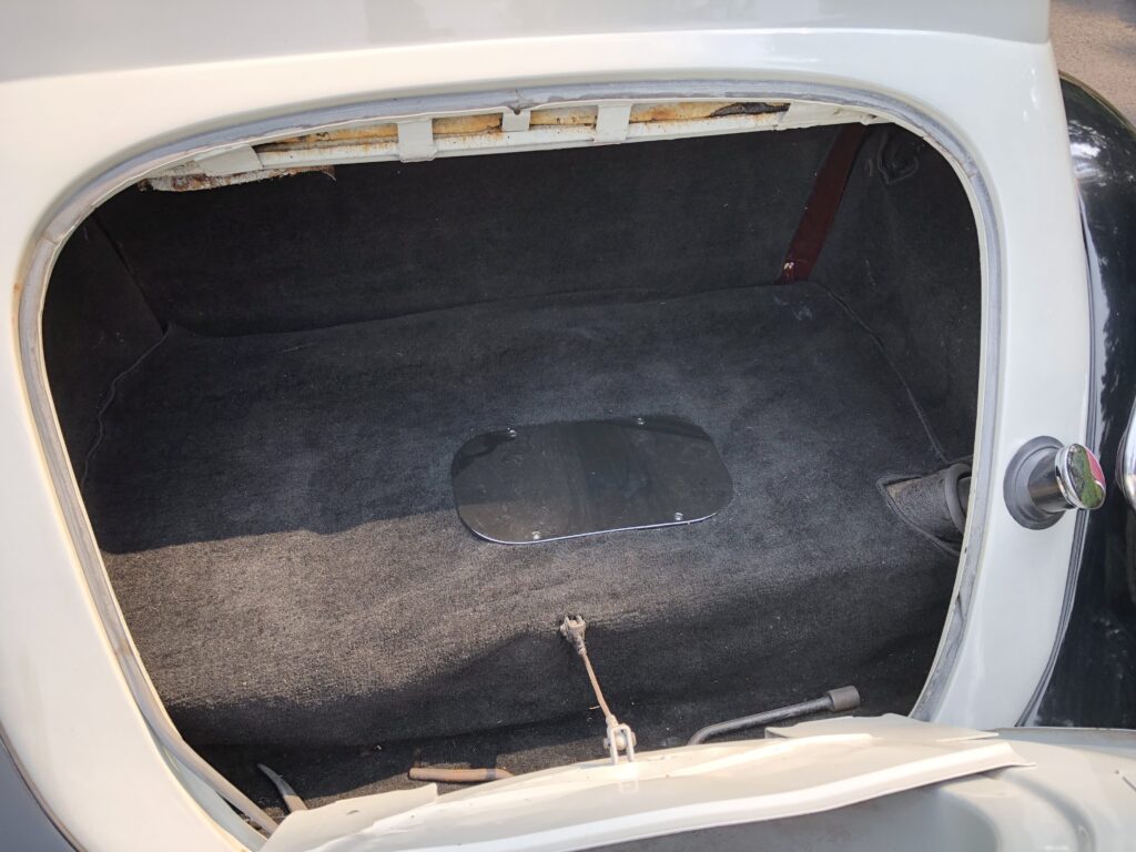
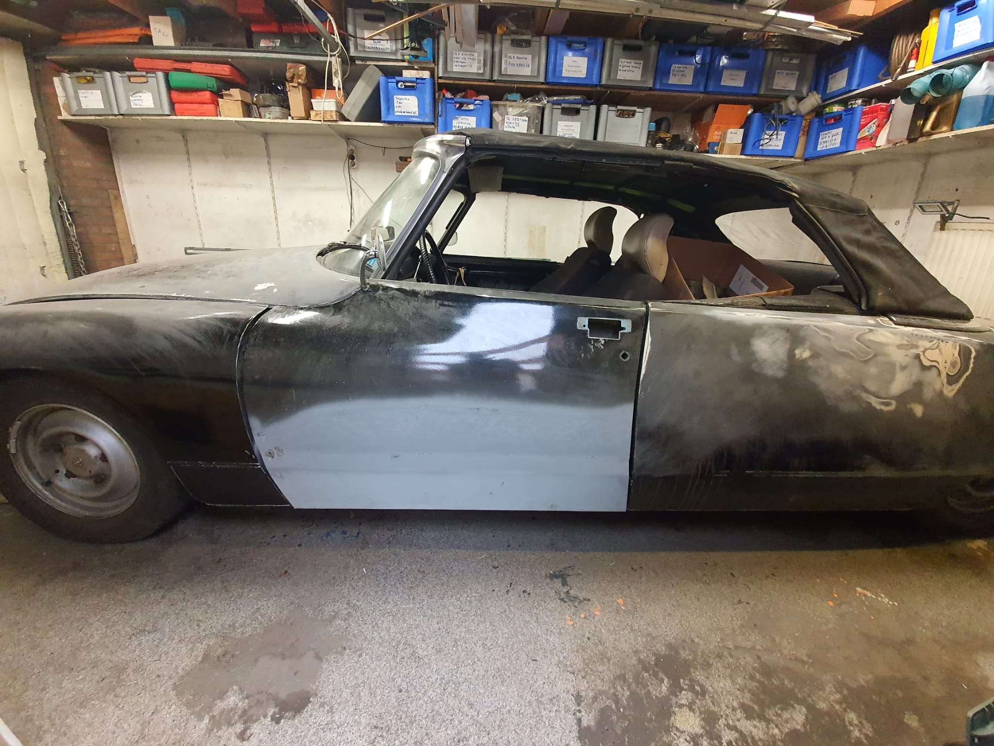
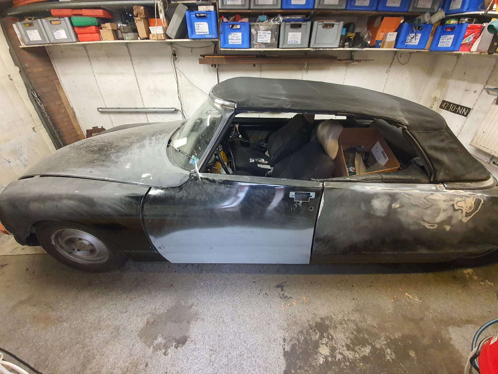
The pictures speak for themselves!

UPDATE 1-2022:

I finally made time to complete the welding on the left door mid of January, 2022.  First, I put the electric heaters in the garage on for a couple of hours, and then I welded the inside part of the new plating fully to the inside of the door.  I also welded tags every 3 cm on the seem in the inner part of the door. After this, I grinded all down so it will later be invisible, at least on the inside of the door since this will not be covered by anything.

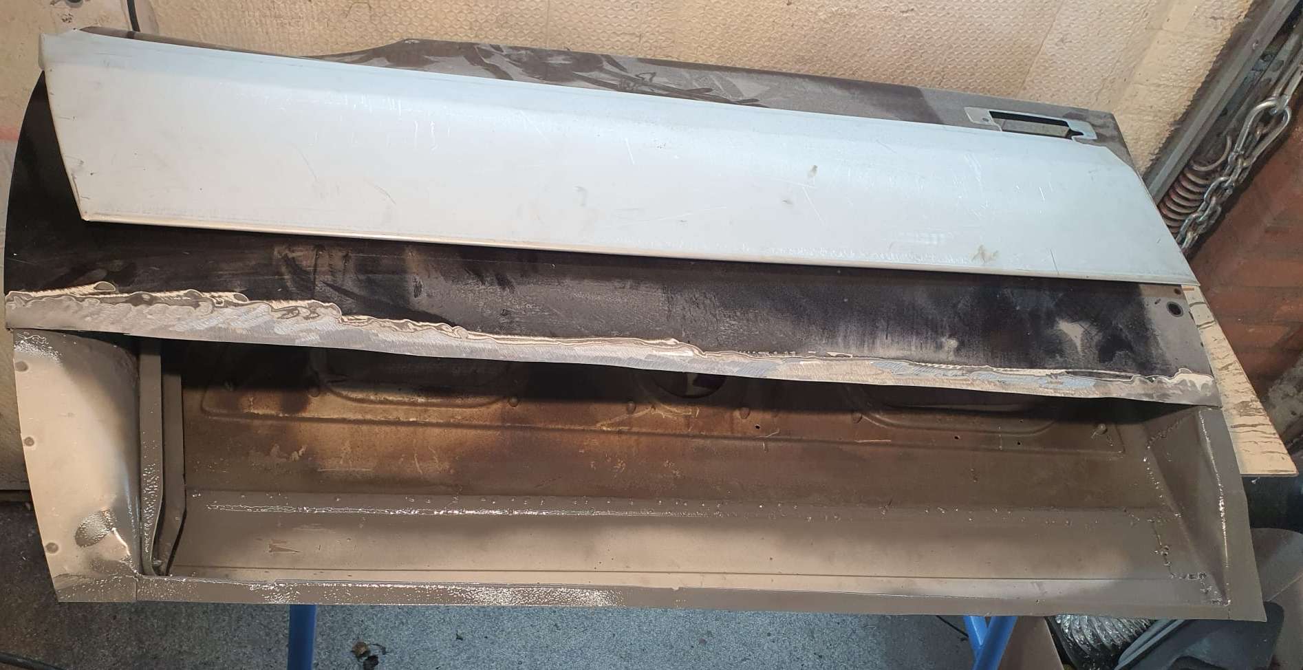
Then, I put the door back in the car, put a lock in and set the door at the correct height- and depth.  Then, I fitted the outer plate on the door and adjusted the cutout and the inner angle of the plate I earlier welded on the inside.  Also- the sides were adjusted and I ended up cutting some 4mm from the rear plate’s lower horizontal part.  The outer parts was just too low for about 4mm. I also had to get 4mm off the cutout of the existing door plate.

I took all parts off that were in the way or made the new plate stick up.  Then, I spotwelded the new plate at its final position.  After this, I took the door with spotwelded plate out, put it on the welding table and used spotwelds every 5cm (2inch) at first, cooling the welded work with compressed air and moved on to slowly weld around until everything was closed.  Then, I tapped the edges at the bottom, left end right around until it almost closed (used thin sheeting to prevent them from getting too tight).  Grinded the weds nicely off, all aound and putthe sinc spray everywhere, including inside the door.

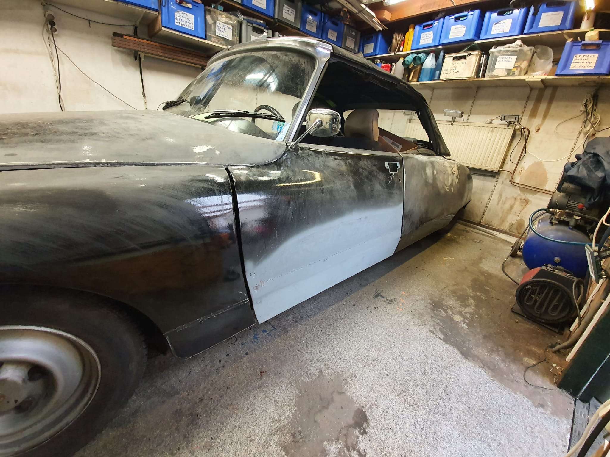
Remounted the door and it all fits beautifuly.

Some mudworks still to do, but that’s all for later!

Welding tip: I use a Gebora 160 MIG machine with 0.6mm wire and mixed gas.  I use the following settings for spotwelding: wire speed to 6 and power is set at 2, that is the 2nd position of max 6.  I found that spotwelding sheet metal when oe of the sheets is around 0.6-0.8 mm,, the setting of power 1 is just not enough to get a spotweld that sinks a bit in, I always get uplifted welds, also if I lessen the wire speed.  But- at power 2, all goes well.  Welding the Citroen’s plating can, however, NOT be done at position 2.  That burns right through the thin plating.

Actually, that is the main reason I always use a bit thicker repair plate so I can at least make decent connecting welds.  You do have to start the spotweld from the thick plate and then move gently just towards the thin palte and stop.   There’s just no other way to do this, imho.

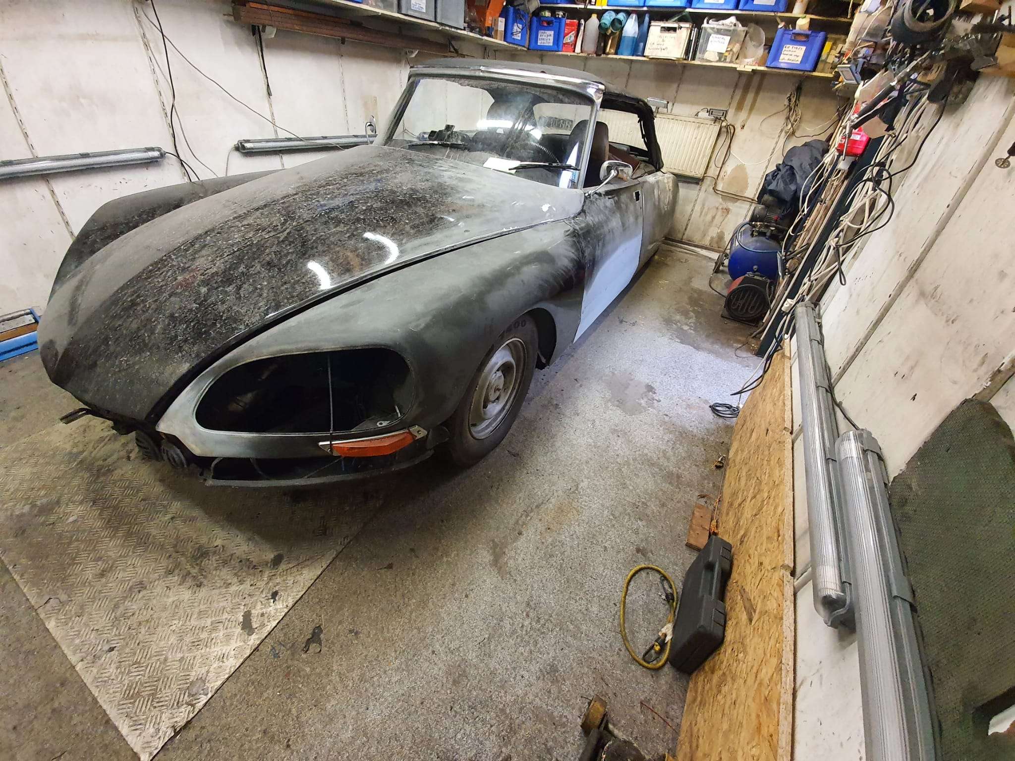
Now, the welding is done. I also welded the connecting hooks of the front fenders already with new connecting pieces for mounting onto the chassis and that also turned out OK.  Next chapter will be the finishing towards 2K primer, sanding and hopefully also painting!

[Best_Wordpress_Gallery id=”71″ gal_title=”Front door repair Citroën ID/DS 1970″]


MACH-3 integrated driver board USB-CNC-MDK2

My main supplier of parts is Aliexpress, and I also buy a lot from Banggood.

At Aliexpress, I recently discovered a board that will interact with Mach3 and has onboard drivers for larger stepper motors like Nema23.

This board takes 24 Volts,  has a USB connection to the PC, an SD card slot and 2 x MPEG/control connectors 15-pin/3-row.

I ordered me 1 of these boards to test it on my CNC mill:

Usb Cnc MDK2 4 Axis TB6560 Stepper motor Controller with Mpg Interface 100Khz Driver Breakout Board

I have this tested with Nema23, 24 Volts and the accompanying firm- and software.

It was quite some puzzling to get the drivers installed and I discovered I had to switch off the Windows 10 security feauture that prevents unsigned drivers to be installed.  You can set this off via a procedure which restarts your PC via a series of keyclicks and restart options in the Windows menu. It can all be found on the Internet.  After this, the board worked perfect.

I also bought a handwheel set, which has a male 15 pin VGA connector, as does the board.  I ended up ordering me a female-to-female 15 pin VGA unit from Ale, will see if this works.

The other 15-pin connector (also male) can be used for simple switches to direct all axes up/down or forward/backwards.  I will use this to make auto toggle swtches directly at the machine, next to the Nema steppers.  I have some nice jogging handles that will fit perfect for this.

Also, I bought e a 4th axis unit hat will get connected to this boardon the Minimill.

chicun

4

5

6

Toolmania WBM16LV Mill with X-Y-Z1 en Z2 reading

GO TO MY CNC CONVERSION PAGE

So, after a long search I finally replaced my very old column drill for a small model column mill from Toolmania.  I had the last one still available from this series.

The old drill -)

It is a model WBM-16LV with an indirect belt-driven spindle with a 750 watt vario motor.  Even at low rpm there is still quite a bit of power on the motor.

This model is actually largely a standard model but with a more powerful motor, with a small LCD for the Z-movement of the 50mm Z-handle and with a wider bed.

The working space with this column router is: X:330mm , Y:140mm and Z:180mm

The spindle has MC2 inclusion with a pull/screw of 10mm.  With this, at least a cutter, drill or head will never fall out.

Toolmania’s standard delivery of the WBM16LV, in use with a drill bit in the drill head supplied as standard and a piece of iron in the clamp
With the two screws you adjust the play. Not too tight and just loose enough to turn smoothly without play. Adjustment can always be done later, when needed.

In addition to buying tools, I always notice that you need at least the purchase value of your tools in consumables and additional tools.  No different for the mini mill.  The glass scales, collets, milling cutters, CNC conversion, gas spring, holders for the table, indexer and so on together cost much more than the cost of purchasing the column cutter.

I immediately replaced the standard 1-16mm rack and pinion drill chuck that came with it with a standard 1-13mm manual-open chuck.  But really, I only work with the fixed spindle heads, collets, and the fixed sockets for both milling and drilling.

The associated stuff like an ER-25 collet holder with 15 collets, boring cutter MC2 and so on are from HBM.

You can see nicely here the X-glass ruler, mounted in front of the X-slide. The X transducer is mounted on the Y slide.   On the left below the bed, you can see the Y-axis glass ruler mounted on the base of the mill. To its left (out of sight) is the Y transducer mounted with a bracket to the Y slide.

The table has been adjusted for play on the X and Y axes.

The vertical column has also been adjusted for play, and screwed very tightly again.

Besides the conversion to CNC I have mounted 3 glass scales of respectively 170 (1x) and 370 (2x).  Because my old display module didn’t work with the ordered glass channels I ordered and mounted a matching new module, this one works with an LCD.

The mill with the OLD display module

For converting the column router to CNC, I have already prepared everything and ordered all the stuff I don’t have in stock.

The column router will be used mainly for milling keyways and occasionally some milling work on ball bearing housings and the like.

The column cutter will also be used for drilling and occasionally for aluminum milling, and then a CNC setup is useful.  The CNC setup will be identical to my Indymill.  It will have Nema23 stepper motors with 1:2 belt drive for X and Y and 1:3 drive for the Z axis. I am going to try to merge the handwheels with the gears and then reuse them so that it remains possible to operate manually. The electronics will again be wifi-based with Duet web-based controller and a cloned motherboard from Mellow (FLY) with 2209 stepper drivers.

The limit switches will be inductive: 2 pieces for X, 2 pieces for Y and 1 for Z-top.

The Z-min (or Zero) will be a probe module for the toolbit, which can be put in a fixed place on the table.  It would be nice if the column could be electrically isolated from the spindle so you could really do the zero setting on your workpiece.  I’m still going to figure that out.

For the Z axis, I ordered a 600mm long gas spring, with an operating stroke of 250 millimeters so the column can move more easily.

Examples from others for my CNC conversion:

This will be pretty much my own solution, only I’m using 10mm base plate aluminum. And I’m going for Nema23 motors. The setup will otherwise be identical to this example for X and Y.
Dit wordt mijn Z-setup. Een gasveer om de druk op motor en spindle te verkleinen en een vlakke plaat op de top van de kolom met een rieaandrijving en de Nem23 motor. . Ik ga voor 1:3 (72 tands op de spindle en 24 tands M3 op de steppermotor.). Als het allemaal past komt het handwiel weer bovenop.
Voorbeeld van de basisplaten met 10mm aluminium.

GOTO the X axis CNC adapter

GOTO the Y axis CNC adapter

GOTO the Z axis CNC adapter

DOWNLOAD ALL MY CNC ADAPTER DESIGNS  as STL, .nc and  OpenScad!

Minimill CNC conversion Toolmania WMD16LV endstops

2021-10-30:  When converting (or upgrading, depends on your P.O.V.) a mill to CNC, it is absolutely necessary to have end stops on all ends. Except the low-end of the Z-axis, an end stop at the Z-axis low end is practically impossible.

On the Z-axis low end another solution has been established by using a Z-stop from the milling toolbit on a fixed X-Y position, OR by testing with the toolbit in place on the matrerial by sight or electronically.

I bought a Z-position sensor for this, which is nothing more than an electrically insulated round pod with a flexible brass top. It is with one wire connected to the Mach3- motherboard as Z-probe and triggers when the tooltip touches the top of the Z pod’s brass top.  Therefore, this trigger is defined as ACTIVE when it is conected to Ground.  Since the mill will be grounded and thus also the tooltip is always connected to ground.  You MUST ground the mill, by the way.  Also for your safety.

Leaves us with the 5 enstops for which I have bought the thinnest available inductive sensors. These are M6 size round and about 8 cm long. These sensors require power, ground and since they are NPN type sensors which means Normally OPEN when NOT active, they will  ground the output pin when activated at reaching the the stop position.  To activate these inductive sensors,  a carbon- containing metal would be best to use and bring the sensor close.  The trigger moment depends on the connected power voltage.  The higher the voltage, the more sensitive the sensor becomes.

I will use 12 Volts or 24 Volts, I will experience a bit with these settings.

NPN and PNP proximity sensors - OMCH

On the net I was unable to find any plug and play sensor holders for my mill, so I developed these holders again from scratch in OpenScad.

Fortunately, I have a lot of starting material in OpenScad from my previous projects.

The X axis left:


The X axis right hand side:


The Y axis front:


The Y axis rear:


The Z-axis top:


Minimill CNC conversion WMD16LV Y-axis adapter for NEMA23 direct drive

While I was making my CNC adapter plates with teethed wheels and belts, I discovered that not much exists that is ready to use for these conversions.

I am therefore also making direct drive adapter parts, to try this out.

This is the first one, starting with the most difficult one.  The rest will be added soon.

Version 1.2 which is 15 mm shorter and much more robust:

The leadscrew has an outside part for the handwheel we will use for CNC that is 10mm, and some thread 8mm.  The thread is needed to be bolting the angular bearings (not meant for side torque) with some torque to the bearing holder.

If you do direct drive, you need a special coupler that can be split in 2. Then, you first mount one part on the leadscrew with some rings between the mill and the coupler part so that the nut can be place in the coupler.  If the thread is too long, grind some off.

Then, put the rubber (with centerhole)  back in the coupler’s mounted part and push the other part in the rubber, so the coupler is complete.

Then, mount the printed adapter with already mounted Nema23 motor on the Y-axis and push the Nema shaft in the coupler.  Use the adapter’s right hand side working window to torque the connector on the Nema shaft and you’re done!

Should you want to have a handwheel as well, you will have to buy a stepper with an axis that is both at the front as the rear. (this is called ‘double shaft’ but is actually a longer shaft, obviously.

OR- my latest design works a bit different: first put a couple of  10mm rings on the leadscrew’s 10mm axle, and then screw a  threaded RVS tube with an outer diameter of 12mm, 25 mm long and internal 8mm thread on the axle.  This goed into a 12 to 8mm coupler and this coupler connects to a NEMA23 stepper motor with an 8 mm axis.  It does get a bit lengthy but it works very well.  Just threadlock the RVS threaded tube to the leadscrew’s 8mm threaded end and it will run OK!

This is the last version, based on the above setup:

GOTO the Dirext Drive X-adapter

GOTO the Direct Drive Z-adapter

DOWNLOAD the latest version of the STL printfiles 

Please donate $1 to my paypal account if you use (parts of) my developed materials so I can continue to share nice stuff for you to download

CNC conversion of my Toolmania WBM16LV (TM BF 16) mill with NEMA23 steppers, 3dprinted adapters, teethed wheels and teethed belts

Before My Toolmania WBM16LV milling machine was delivered I already had plans to convert it to a CNC milling machine.

I do have some experience with 3d printing, and I have 2 CNC routers up and running, like the Indymill.  So, the conversion of this mill will not be difficult in the Technical sense.  But- making the perfect designs for the adapter plates of the Y- and X- axes proved to be a lot more work than I expected.

The column cutter is already equipped with glass scales with digital readout.  Furthermore, there is a gas spring mounted on the Z-column so that not all the weight is in the way when moving back and forth.  Also an automatic lubrication system for the slides of X, Y and Z-axis will be mounted.)

DOWNLOAD ALL MY CNC TEETHED ADAPTER DESIGNS  as .STL files

The electronics will become OpenCNC + wifi + wireless controlbox. I received the kit and will put it together the coming weeks.  For now I am going to set the mill up with my all-in one USB-CNC-MDK2 board.  I use this for all of my routers and mills to get it set up in first instance since it is very simple and sturdy. And- you can run it instantaniously without any PC or programming, just with the handwheel or from SD card.  And from the laptop, of course.

GOTO the X axis CNC adapter

GOTO the Y axis CNC adapter

GOTO the Z axis CNC adapter

DOWNLOAD MY CNC ADAPTER DESIGNS  as .STL files

LATEST NEWS:

After this all worked well, I also made designs for  NEMA direct drive adapters on my Toolmania MiniMill:

Direct drive adapter for the X-axis
Direct drive adapter for Y-axis

Above: Direct drive adapter for the Z-axis

left top the Z-axis adapter, right the X axis adapter and at the bottom the Y-axis adapter

What makes it tricky is the choice to make: Will I replace the spindles with ball bearing spindles or not?  Not for the time being, first let’s make everything on CNC and then I’ll see how it goes.

error: Content is protected !!