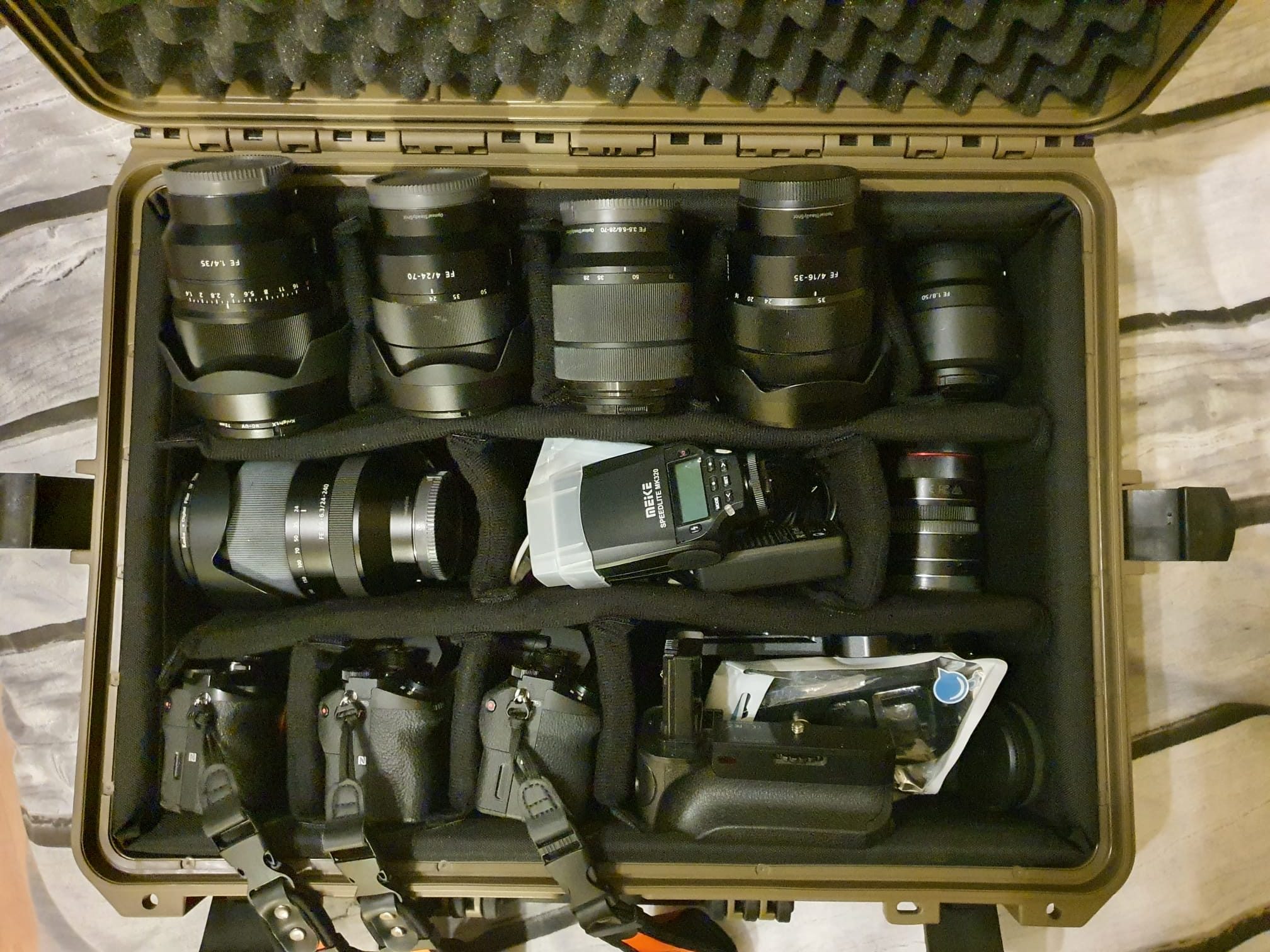
Every now and then I still use my Sony A7-RII , A7II en A7I set and accompanying lenses for outdoor shooting.
But mostly for city use I take the small bag with the Canon RP and the short zoom lens.
It’s just a bit easier to handle.
And for sports work and fast recordings I still stick to the M3/4 format cameras from Olympus , with the pro lenses attached. Also very nice for 4k video!
Due to growing demand of raw materials, required to produce large capacity batteries for electric vehicles, prices are rising and the development of batteries that require less expensive materials is growing.
Lithium-Ion is almost always the basic component for existing EV-batteries.
The way that the current is brought to the Lithium is via a cathode and an anode. The used materials for these cathode and anode differs, and this has great impact on stability, life span, kw/gram thus maximum current and deterioration behaviour of the batteries.
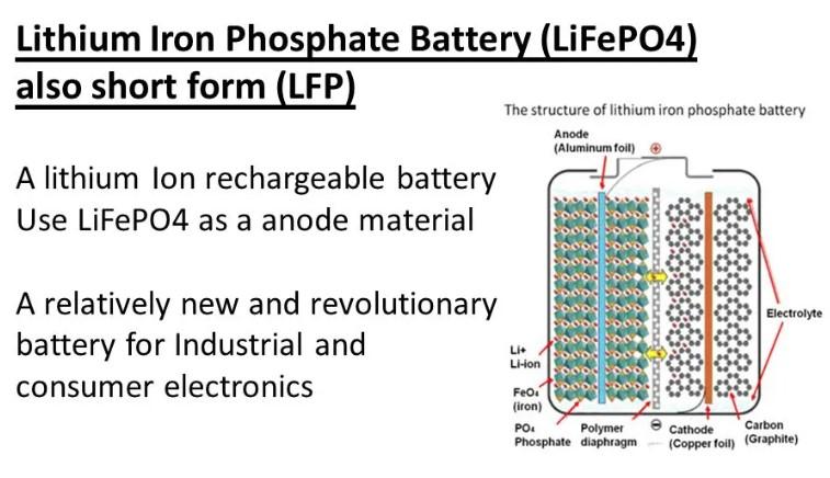
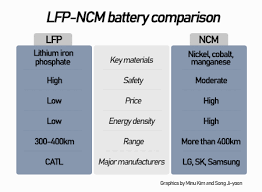
LFP batteries
Recently a new type of battery has been developed, using another type of materials for the anode and cathode than NMC batteries:
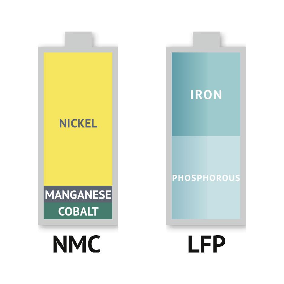
The difference between NMC and LFP anodes
The lithium iron phosphate battery (LiFePO4 battery) or LFP battery (lithium ferrophosphate) is a type of lithium-ion battery using lithium iron phosphate (LiFePO4) as the cathode material, and a graphitic carbon electrode with a metallic backing as the anode.
LFP can be cycle-charged to 100% at least 2000x.
But LFP batteries (and -by the way- NMC532 as well) are less compact than NMC811 and NCA batteries. That is because LFP batteries have less electrical capacity per volumetric unit than NMC811 and NCA batteries.
The result is that smaller to medium sized cars will not be able to carry more than an 50-55 kWh LFP battery pack.
It is expected that LFP batteries will become cheaper than NMC type of batteries in the long run because iron phosphate can be made without material availability restrictions, while the required raw materials for NMC and NCA batteries will become even more expensive over time.
NMC (or NCM) and NCA batteries
The mainstream of Li-ion batteries, however, is currently NMC (and Tesla’s NCA long range and LFP standard range), with different types of battery composition.
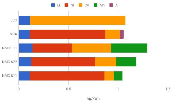
Tesla’s NCA development of batteries for the Tesla3 long range and new Tesla model S long range types has its own kind of composition for the batteries as is also shown in the below raw materials overview:
Raw materials per type of battery: Lithium, Nickel, Copper, Manganese, Aluminium
NMC811 batteries
The latest development within the NMC type of batteries is NMC811, which has more power in a smaller pack but requires a very strict producing method and a very tight Battery Managment System.
NMC811 batteries will deteriorate quickly if they are repeatedly charged at their max power capacity and it is recommended to charge the battery pack as little as possible above 80% of its maximum capacity.
And- it is recommended to only charge to maximum capacity when the charge will be used immediately after charged. For instance when a large trip is made, before heading off and in between the trip.
NMC811 has a maximum full charge cycle of 200-300x, when performed according to the recommendations. This might be the main problem with these type of batteries, but in practice it might mean a lifespan of over 8 years. Provided that you only charge to 100% for the holiday trips.
NMC811 makes it possible to equip a small/medium sized EV(SUV) like the MG ZS EV (2022 version) long range with a 74 kWh NMC811 battery pack.
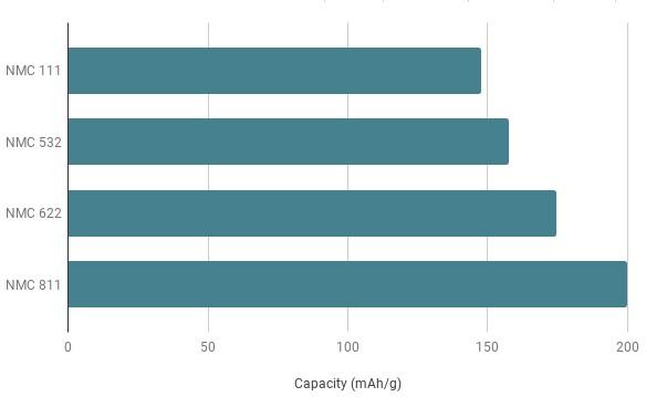
Capacity versus weight (and also related to volume) of NMC type of EV batteries
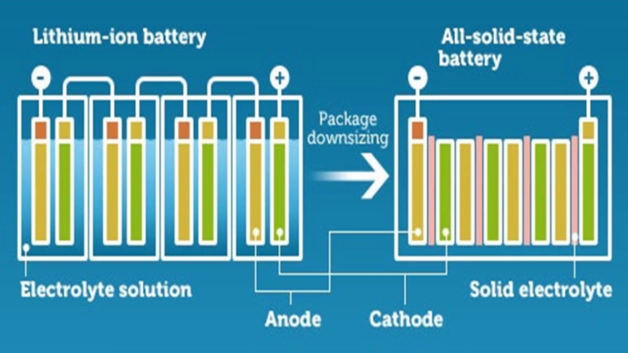
Solid state batteries
Solid state batteries are also becoming available, and these batteries provide the best performance in a similar – or possibly even smaller build volume than NMC811 batteries.
But Solid state batteries are still quite expensive and are not commonly available.
Toyota is one of the main developers of solid state batteries and will equip their hybrid cars with these batteries.
It will be interesting to find out wether solid state batteries will outperform the older//existing type of batteries in the long run, since hybrid cars make maximum use of the charge/recharge cycles.
Summary
For small EV’s, LFP will be the best choice. (less range required, usually city cars. USP of LFP: 2000+ times possible to chargecycle @ 100% full capacity.
For the mid-to higher segment, NMC811 and/or NCA will be the best fit. USP of NMC811: more capacity makes longer range possible, with requirement of a very good BMS. Due to less usage of expensive materials in NMC811 (less cobalt&manganese) the price for NMC811 is within affordable range.
For the highest segment EV’s, solid state will be the best option. Solid state is more expensive, smaller, more capacity, recycling to full power is no problem.
For Hybrid EV’s either LFP or solid state can be applied, but not NMC811.
If you look at the current rules for noise and noise pollution from motorcycles, it seems like a jungle that you can’t get through.
What is clear is: If you do not meet the noise standard, there is a chance that your motorcycle will get impounded OR your registration of the bike gets invalidated and you will no longer be allowed to drive on public roads.
Noise and older engines
For older engines it is in usually not known what the maximum noise allowance in dB(A) is.
This does not mean that you can produce an unlimited level of noise.
Therefore, general guidelines for this type of vehicles have been drawn up y the Dutch government.
The cylinder capacity of the motorcycle is leading in those guidelines.
These sound values are of course always dependent on engine revvs.
For example, in the Netherlands the sound of engines built before 1960 should be measured at 2000 rpm (4-stroke) or 2250 rpm (2-stroke). For motorcycles built after 1960, these rpm’s are respectively 4000 and 4500. For a Harley, at 4000 rpm it is actually only possible to stay under the standard of 106dB(A) with well damped exhausts.
Measuring motorcycle noise by the police
The Dutch police measures sound output stationary.
The microphone is placed at 50 cm from the exhaust mouth at an angle of 45 degrees (may deviate 10 degrees).
The rpm sensor is placed on the spark plug wire. If that is not possible the police measures the pulses of the ignition coil.
The RPM is entered into the measuring equipment.
The law-enforcer then turns up the gas three times and the highest noise level counts.
Just to average: If you get above 110 dB(A) with a heavy engine at 4000 RPM, it costs money.
An after market exhaust may (according to the rules) not produce more sound than the original exhaust.
But in practice, especially in the past, many open exhausts were sold and mounted.
And with such exhausts it is impossible to get below the legal noise standard with any kind of dB-killer.
And now what?
If you want to avoid all this misery, it is better to make your exhaust system meet the required test standard or at least the standard that applies to your bike.
This can be done in various ways:
Either you mount on your motorcycle an original exhaust system, as present at the original delivery and stay within the license plate related standard;
Or you make sure that exhausts are mounted with the E4-Dutch approval standard, appropriate to the year and type of motorcycle and stay within the vehicle’s registered standard;
Or if there is no testing standard for your motorcycle: Make sure the exhaust meets the ‘general’ Dutch testing standard of 106 dB(A) at 4000RPM (for engines of more than 1000cc).
My solution for less noise:
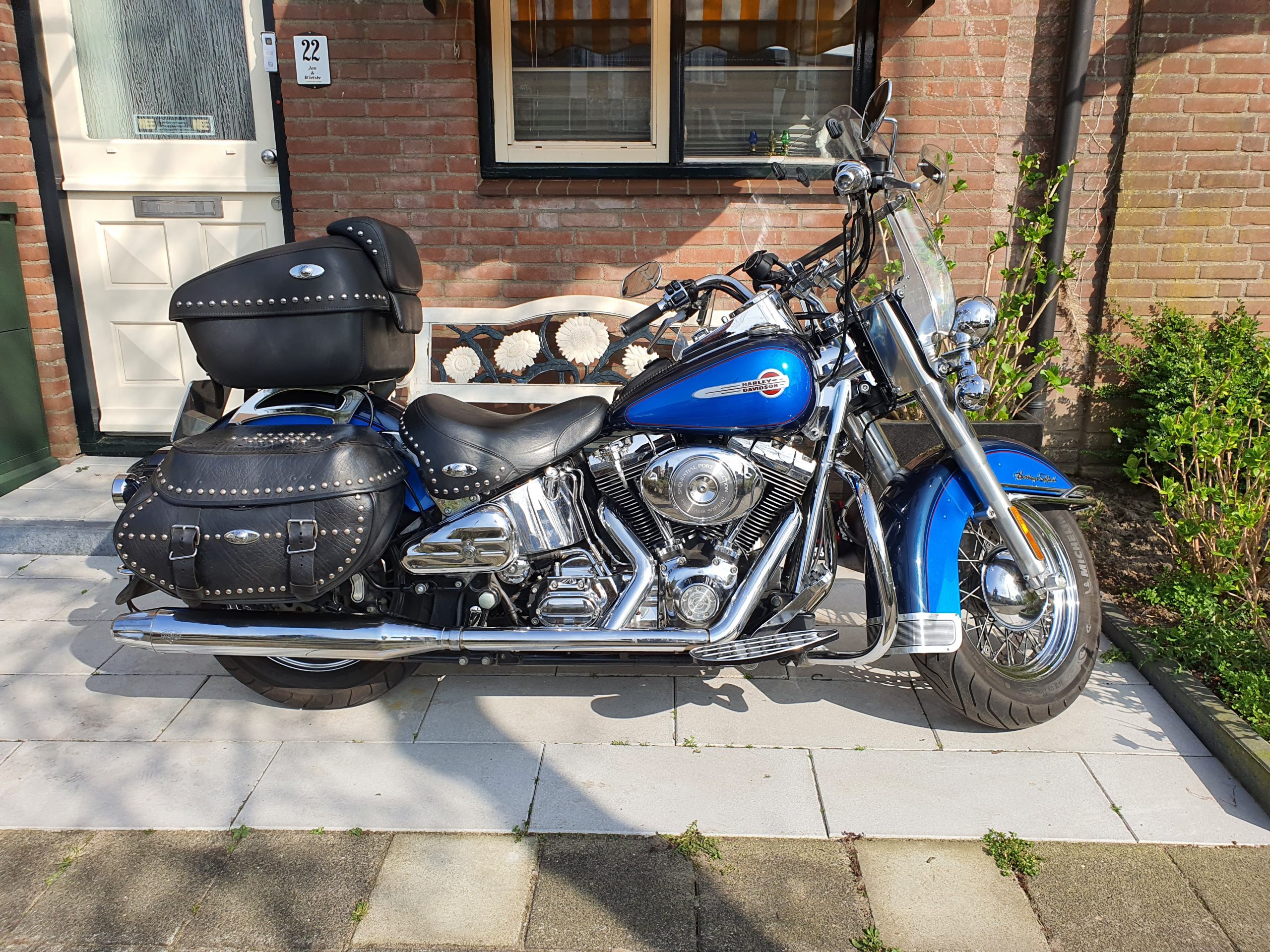
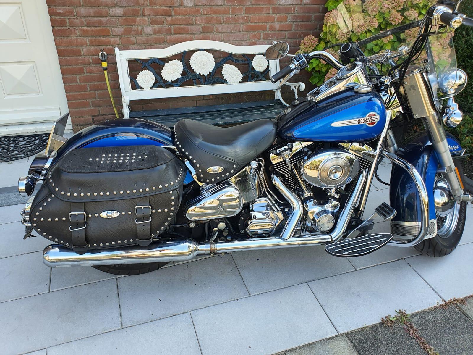
My 2004 HD Heritage FLSTCI originally had European approved exhausts with E4(NL) approval when delivered.
But when I bought it in 2019 it had an aftermarket ‘real dual’ V&H eliminator 400 open exhaust system mounted without baffles:
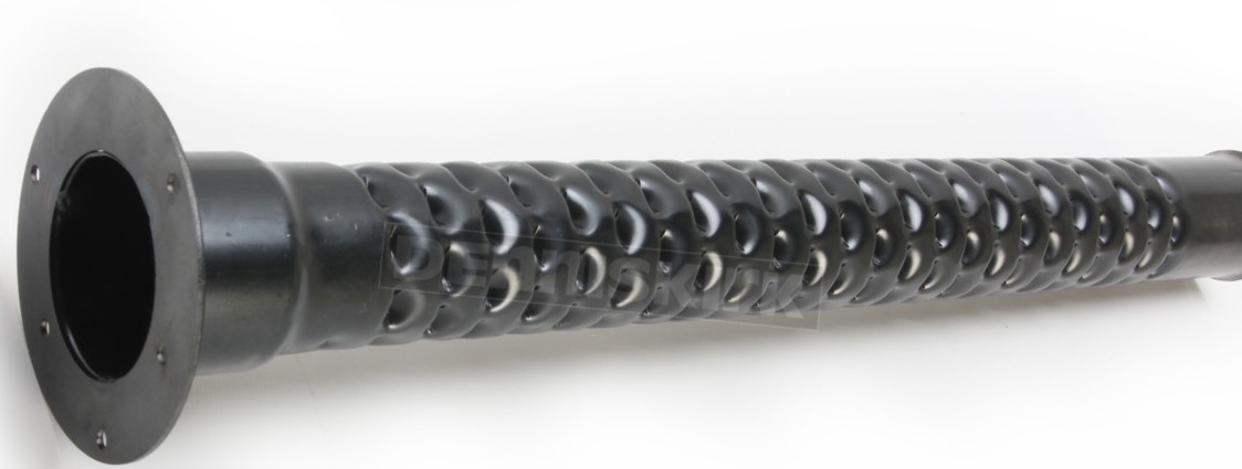
I tried reducing the noise by mounting an original baffle set from V&H with silenced baffles, including a damping pack with fiberglass mat, rolled up around the baffles.
Then I mounted everything and indeed much less noise, but above 1000 RPM still much more noise than the allowed 106 dB(A) as stated in the licence papers of the bike.
So, this did not solve the noise level in the end.
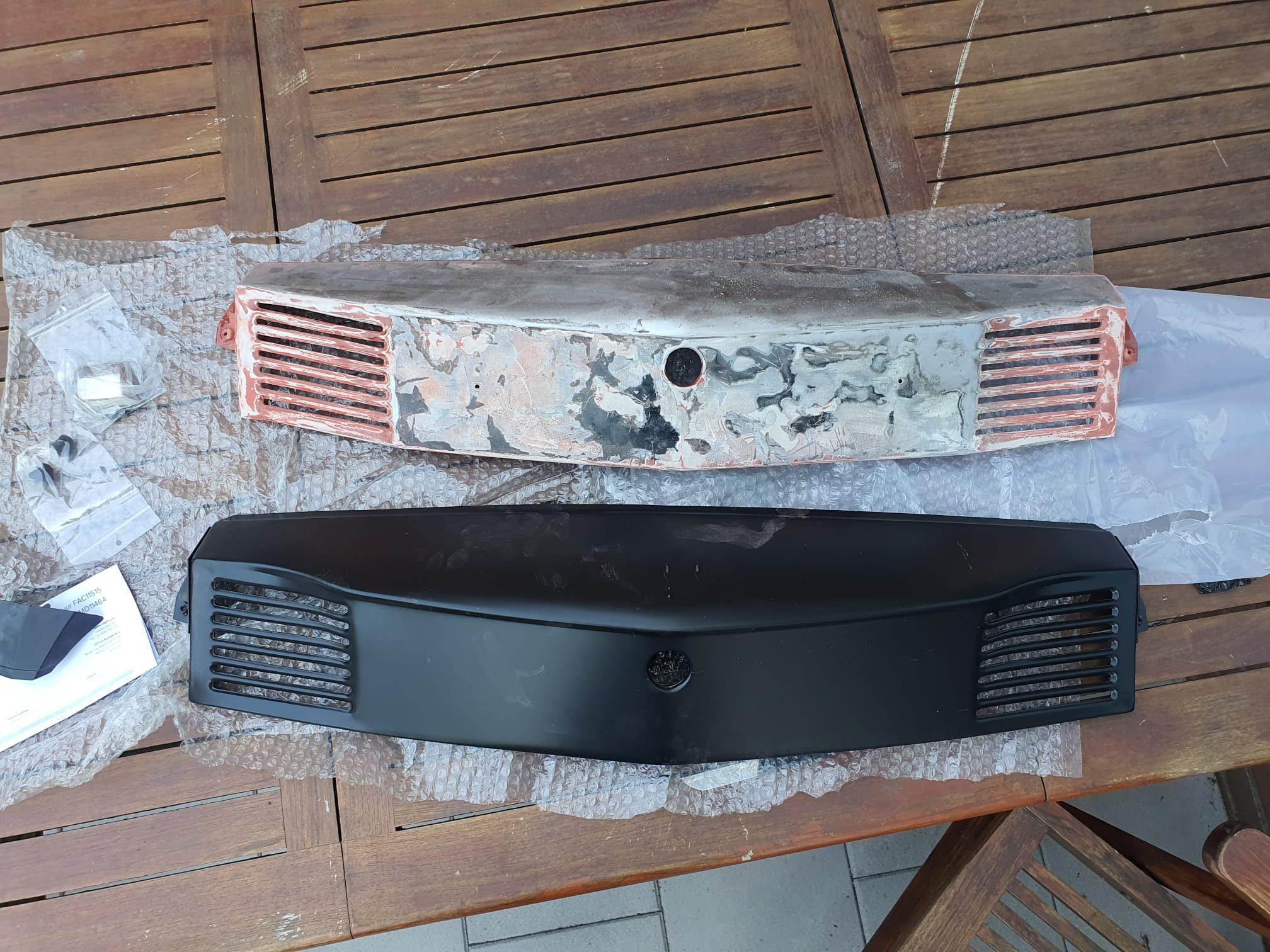
Final solution
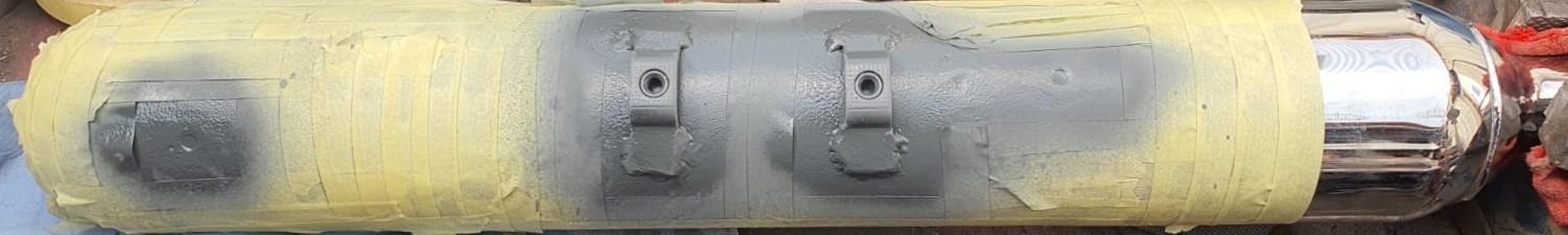
Finally I was able to get my hands on a used set of original HD cruiser exhaust silencers, one of E1 (German origin) and one E4 (Dutch).
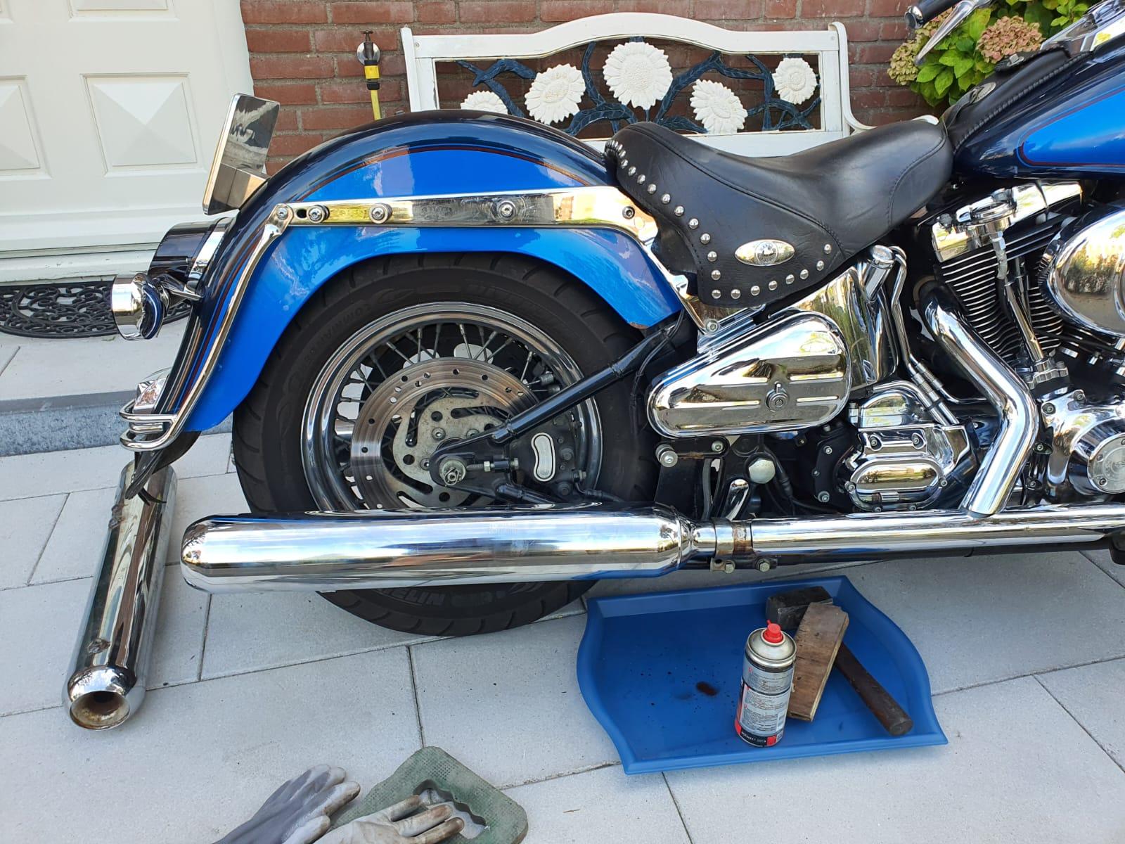
These I will mount, even though the mounting brackets have to be moved on the silencers.
Many of these silencers have been intentionally demolished internally, so you should be careful what to buy!
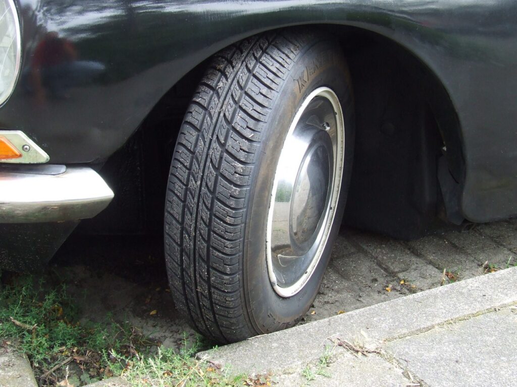
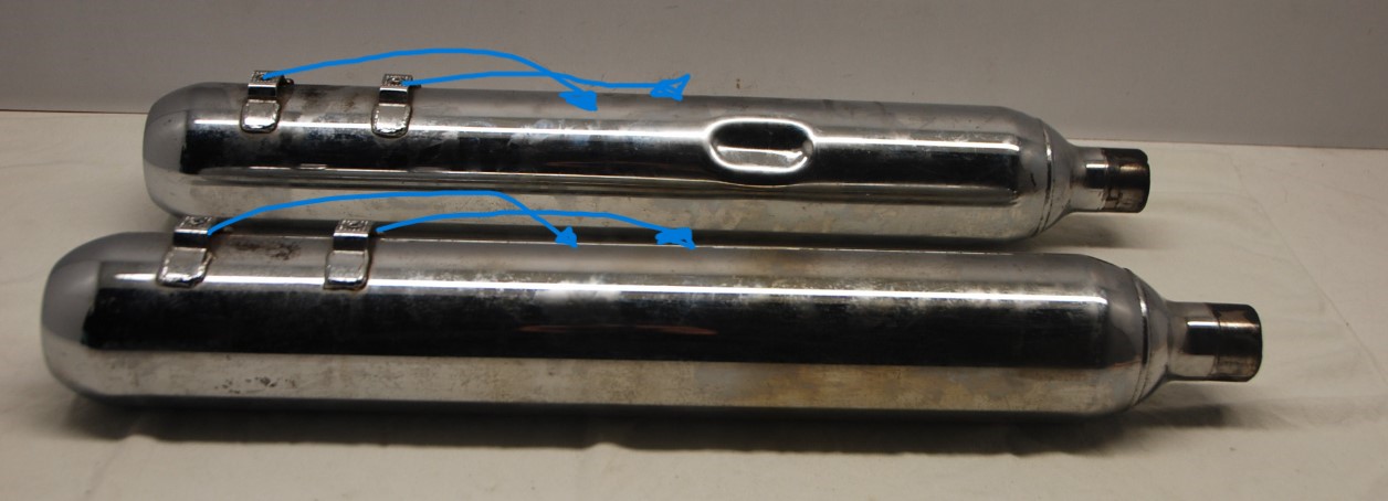
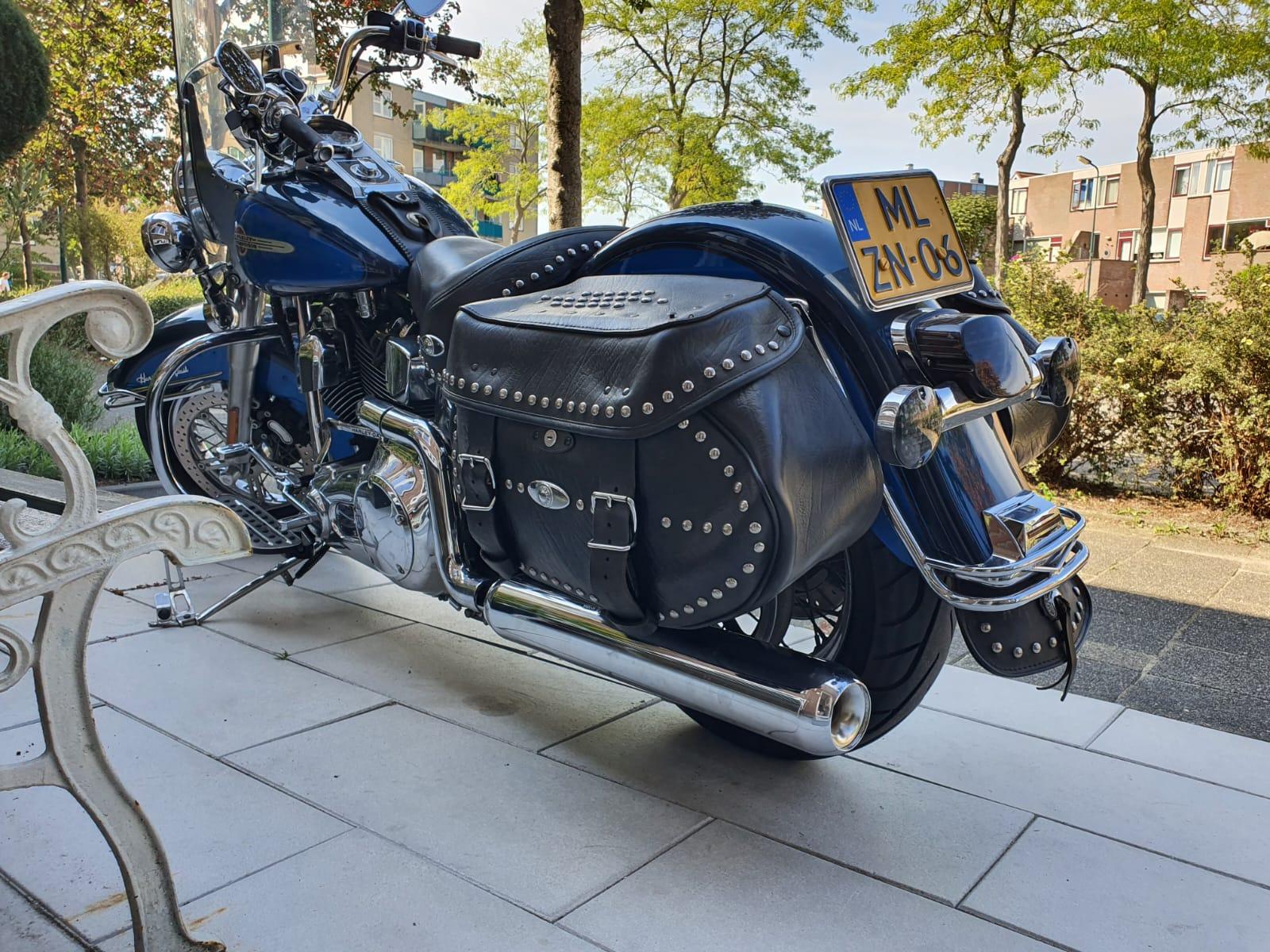
The bike, still with the V&H silencers mounted.
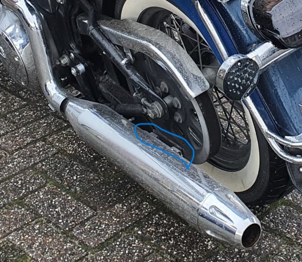
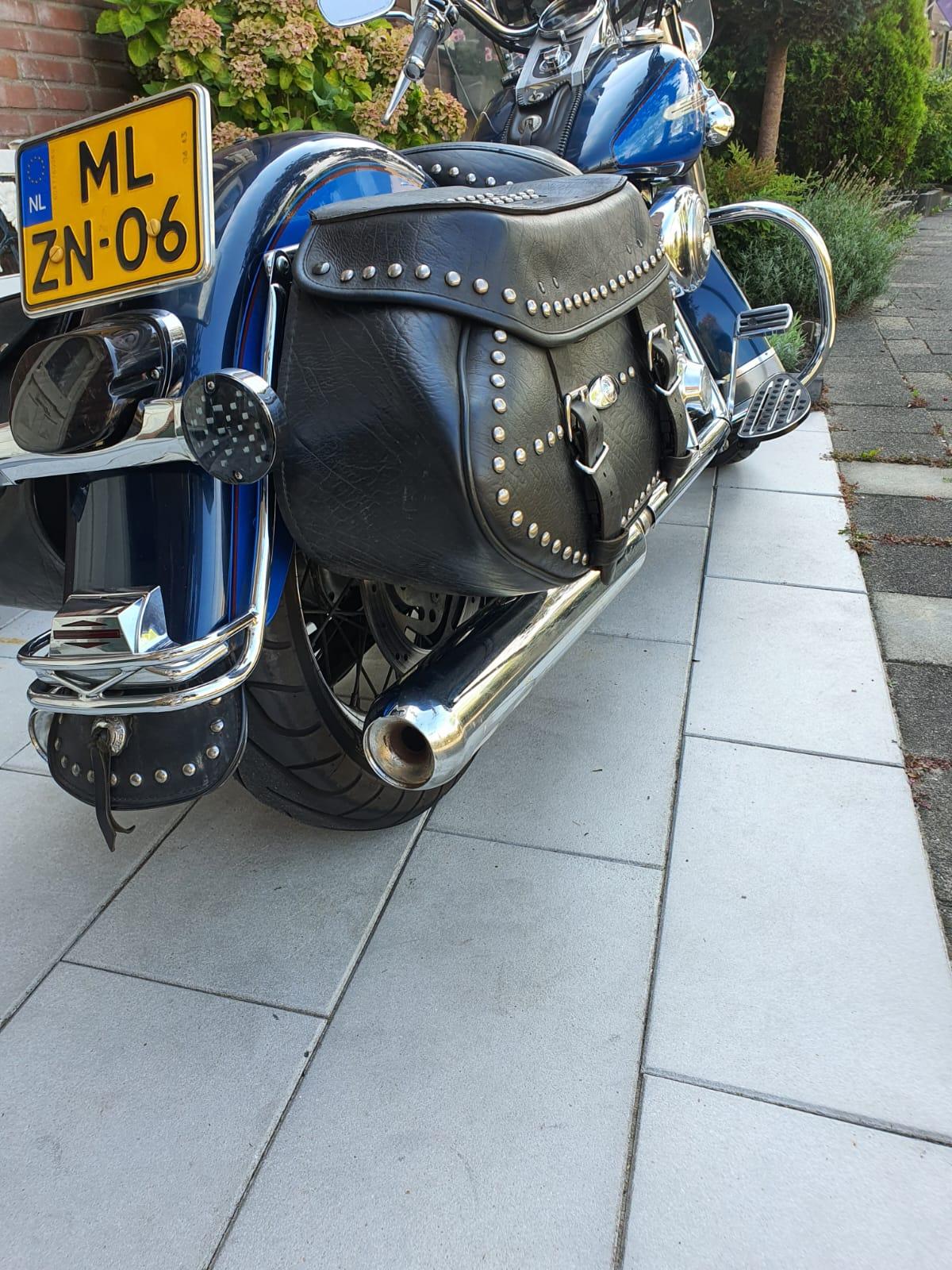
Below the existing mounting points of the Vance&Hines Eliminator 400 brackets and mufflers are shown:
With these HD Catalist E1 marked exhausts I am now in whisper mode, which is very much appreciated when driving through big cities
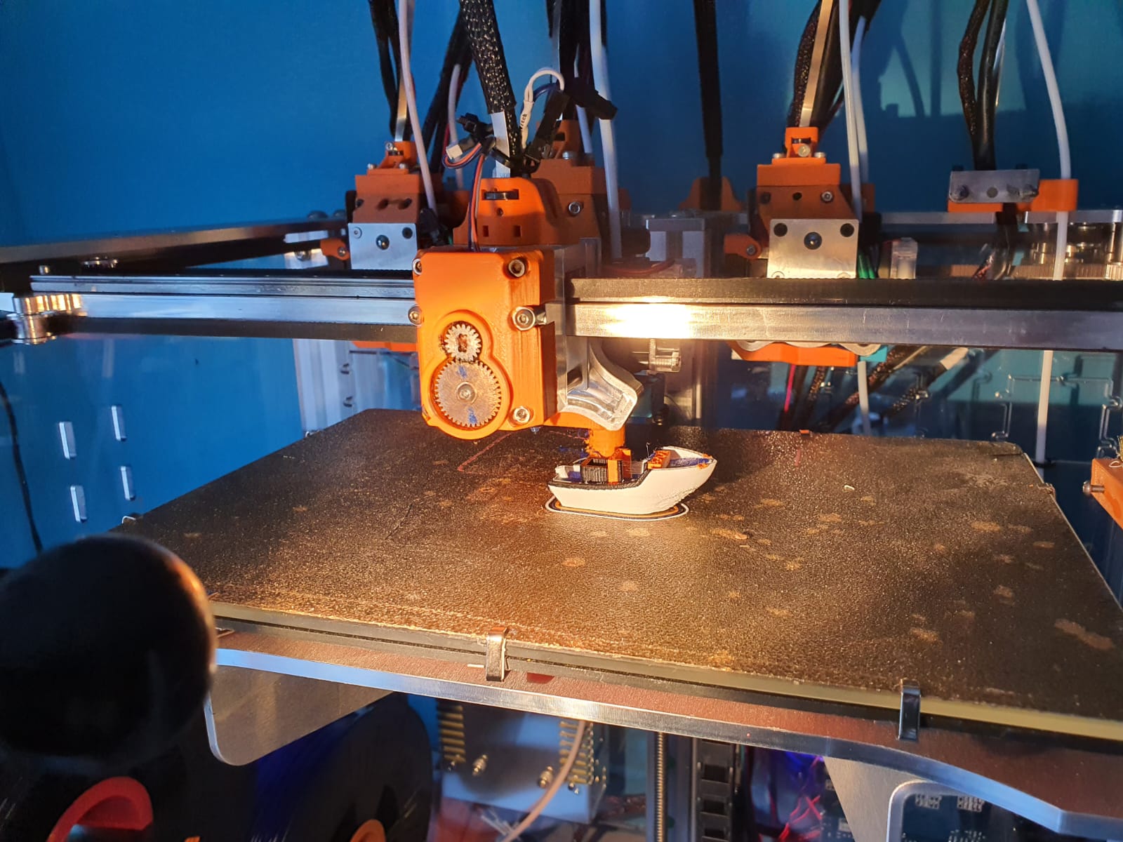
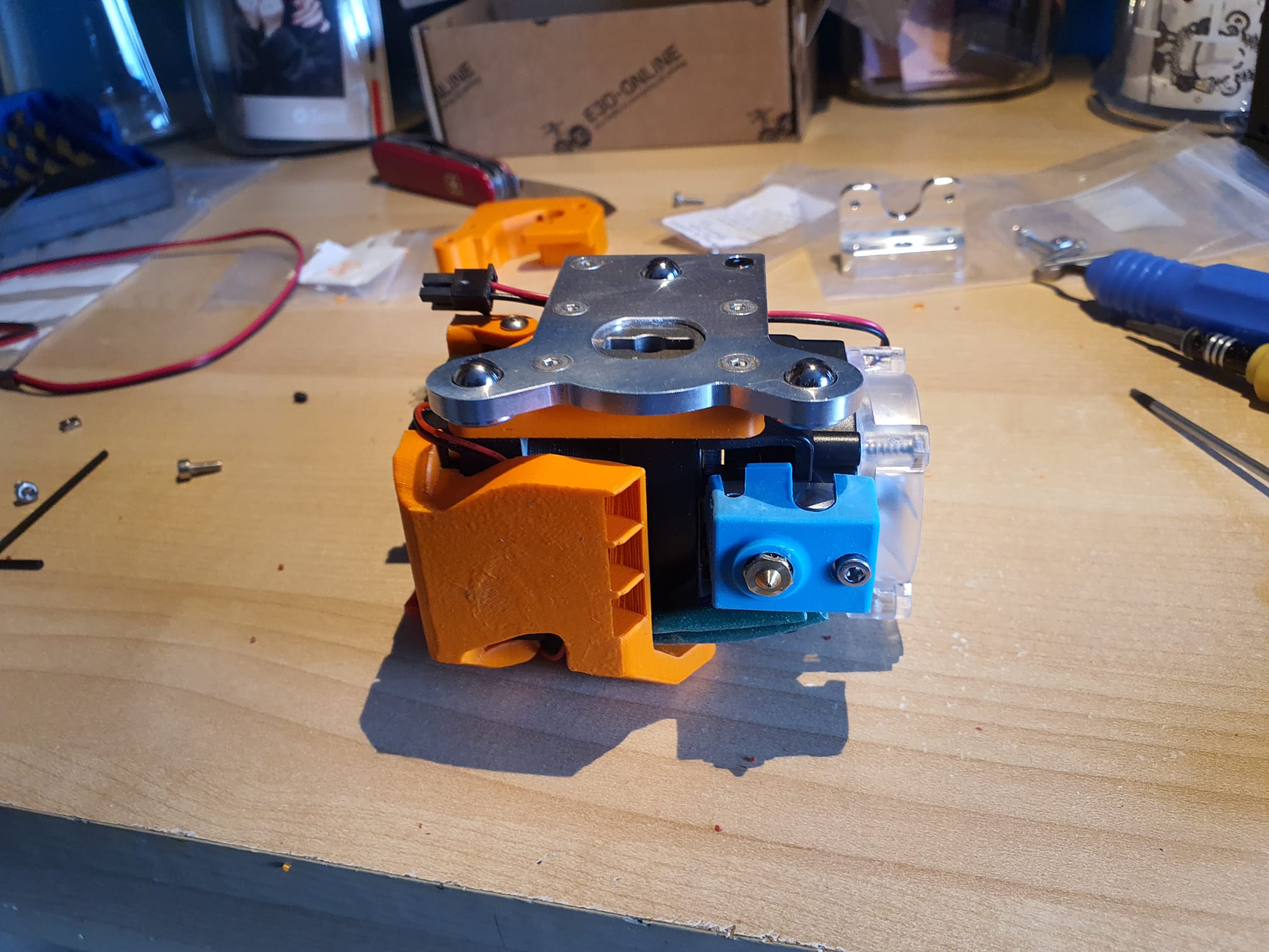
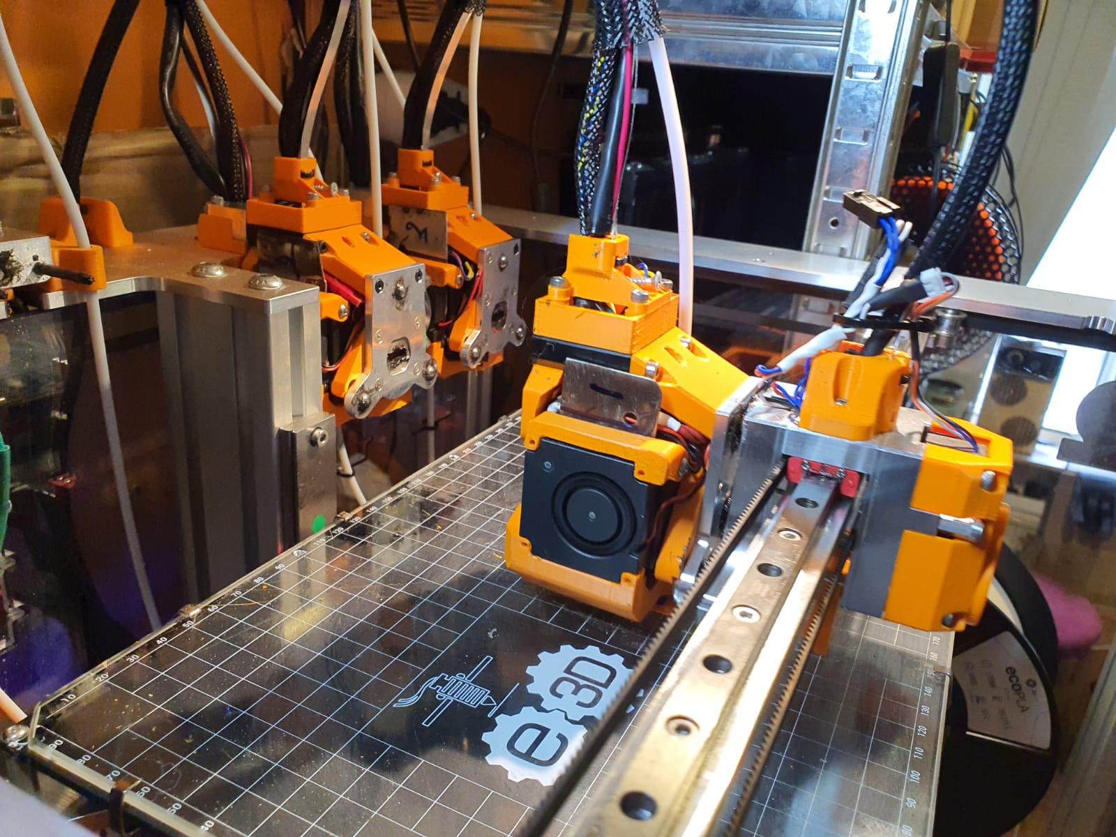
In the end, the solution to my intermittent on/off problem with my toolfans on the Hymera direct drives was extremely simple.
The picture shows the solution, as the Hymera stepper driver obviously interferes with the 40mm fans. The problem was that these fans 2,4,6 and 8 not always started spinning.
I tried to exchange the fans which did not help, tested the Voltage, current , settings and so on. Everything appeared to be OK.
Strangely enough, when testing the fan off the Hymera tool, even including the duct attached, everything woked fine. Just did not work when mounted on the Hymera.
Finally, Just trying some things, I pushed a thin steel plate (NOT RVS) in between the fan and the stepper motor, and now it always works, even at 5% PWM! Problem solved!
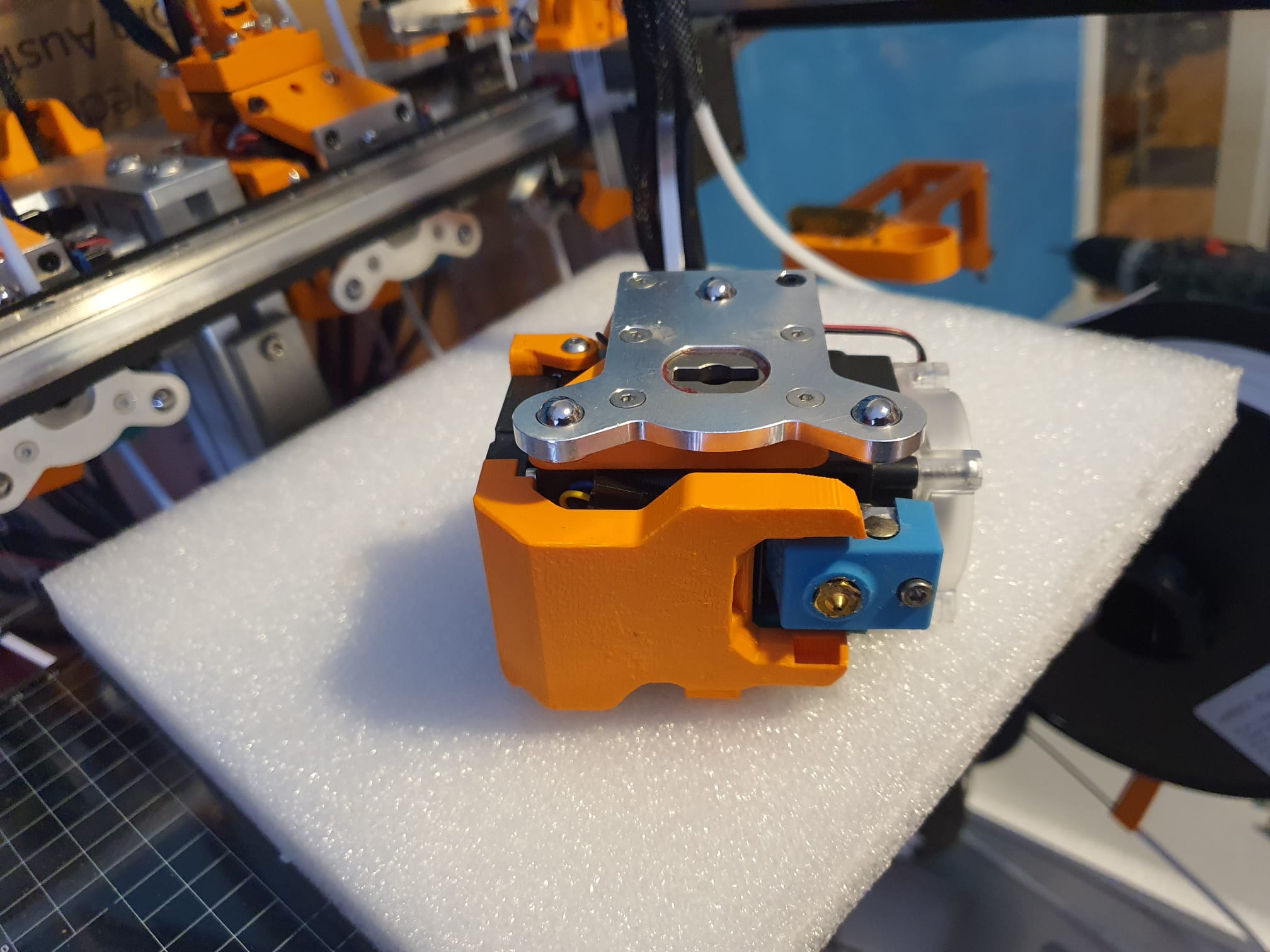
After testing at all tools, I made 4 better fitting thin plates and mounted these at the 4 tools and no problem exists anymore, ever since!
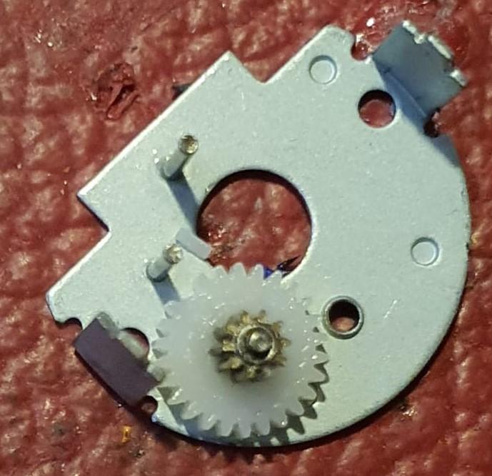
The toolhead stepper of my E3D toolchanger system suddenly broke down.
The cause was a failed tool pickup move, due to which the rotating axle of the toolhead pickup system got blocked.
After exchanging the stepper I changed the Duet’s settings so the C-drive will not be able to generate too much torque.
This will prevent the last teethed wheel to break whenever the driven pickup axle gets blocked under extreme circumstances.
After opening the case of the failed reduction box, I discovered 1 broken tooth of the final gear.
I ordered me a new one, and mounted this. And I changed the C-drive’s settings to make use of the stall mechanism. It took some tweaking to get this to work properly. After all, picking up a tool must still work as this is the base intention.
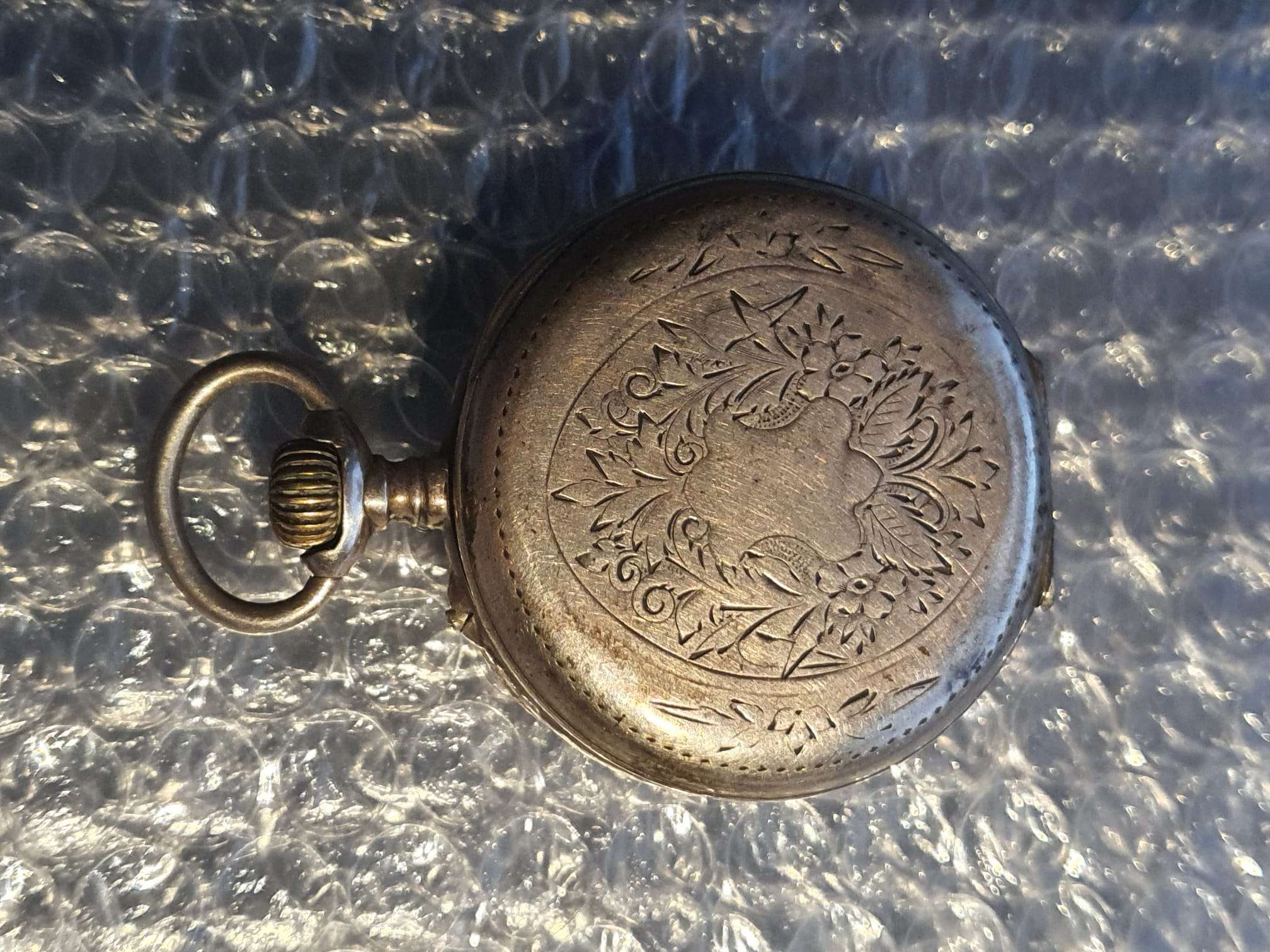
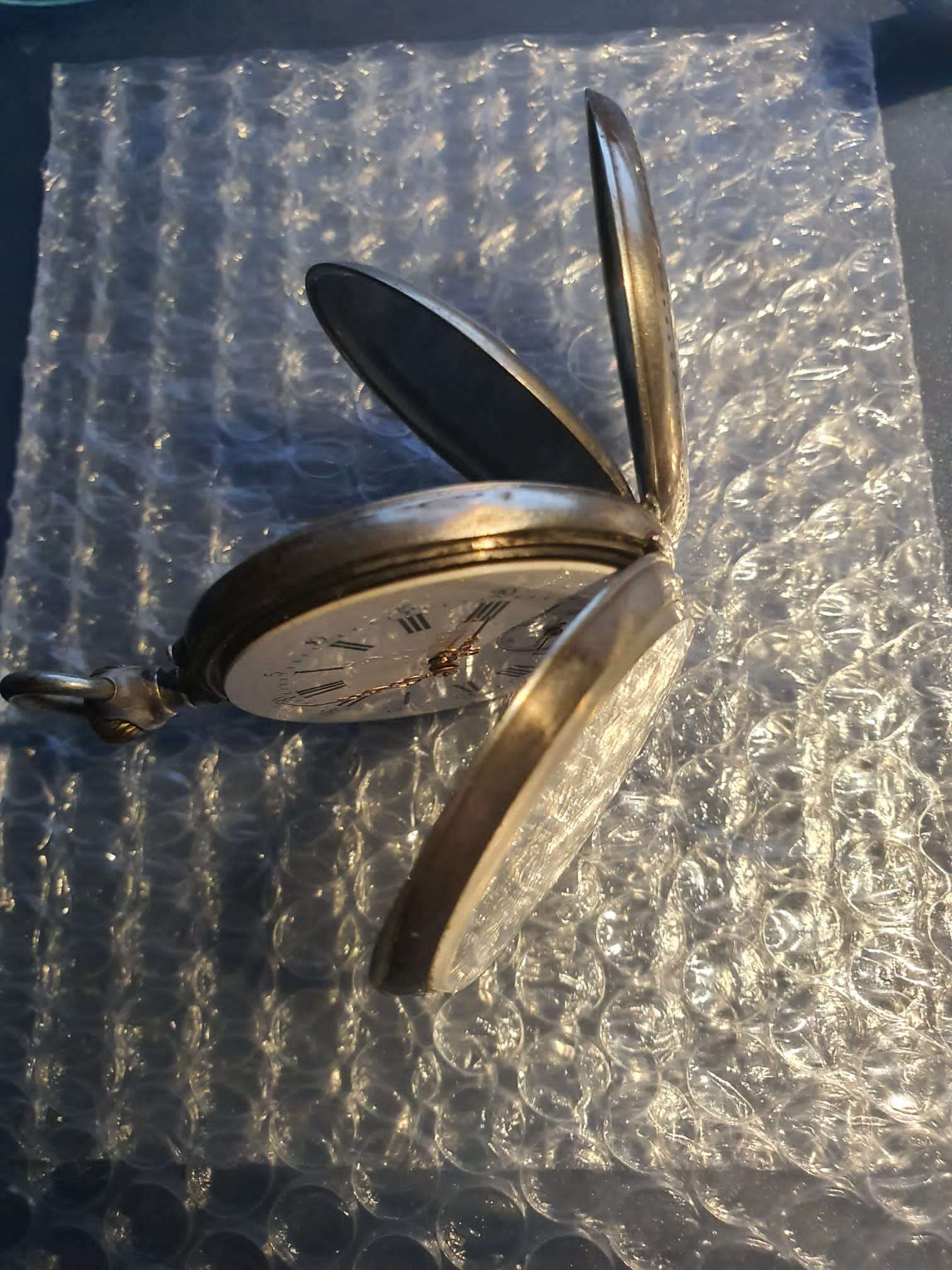
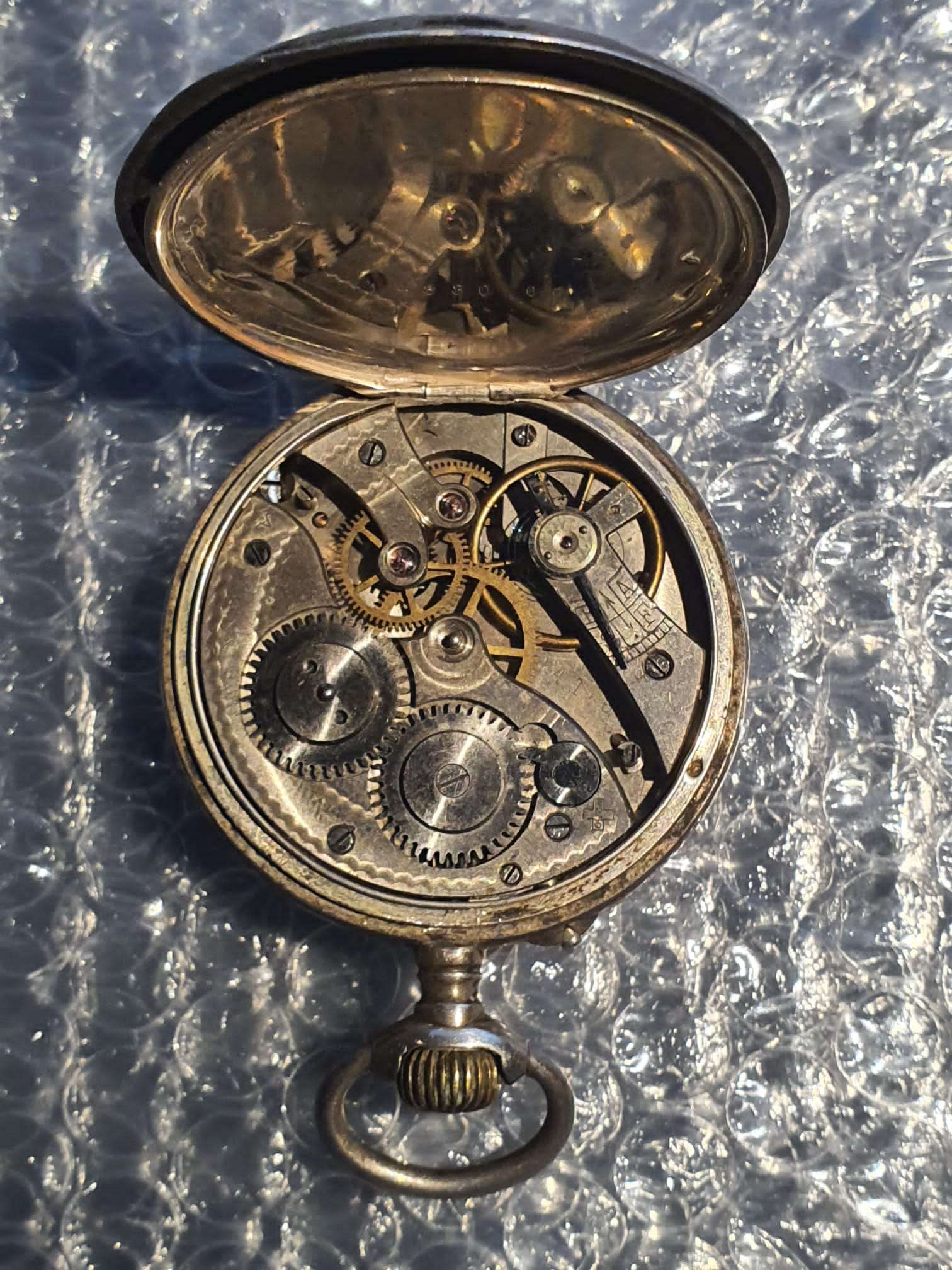
I bought this watch on eBay, state to be a pre-WW2 pocket watch.
It does not run and the main spring appears broken.
But- it is in a repairable state and everything moves easily.
Most importantly- it has not been tampered with.
In my search for similar watches i could not find any with identical inner mechanics, all watches that appear to be alike have different gears and so on.


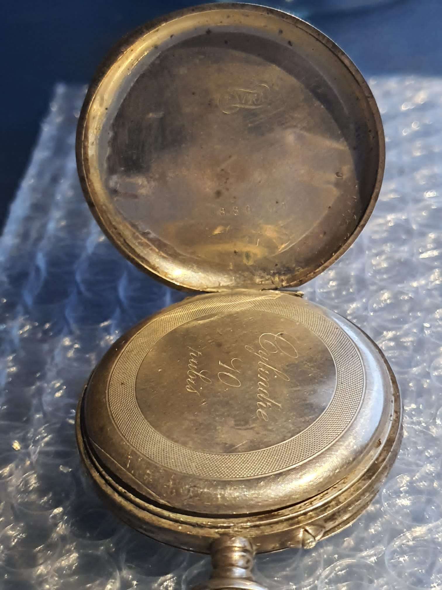 Pocket watch ‘Cylindre 10 rubis’