Disc brakes for my Citroën Traction Avant

October 2021: Since a few weeks I have been in contact with Pierre Duperrey, and bought his brake disc kit for the Traction Avant 11BN/L.

THE INSTALLATION MANUAL FOR THIS KIT IS AT THE END OF THIS ARTICLE!

Also, Pierre was so kind to guide me to the sellers of the brake calipers, -pads and -discs.

Pierre has developed a system to get disc brakes on your Traction Avant.  And the way he made this, it will not be visible on the outside of the car, nor in the motor compartment.  Only when you look under the car it becomes apparant that it is not what you would expect to see.

The developed kit is extremely sturdy, and the developed 2-part saddle that is mounted on the inside of the existing mounting sleeve that is in the old situation carrying the brake mounting plate of the drum brake system, is very solid.

From Pierre you can buy a set that fits to your existing stub axle bowl and the brake calipers are attached with a newly made saddle at the points where the brake anchor plate of the drum brakes is now attached.

The main part of the saddle exists out of 3 laser-cut parts that will need to be machined into 1 part, that attaches to the 2nd saddle part to enclose the mounting plate on the axle bowl.

Pierre communicates in French only, and I established a good understanding between us by using Deepl.com to translate French to Dutch and vice versa.

The right hand sided disc brake construction including the new brake line

Pierre supplies all the hardware that you can’t actually make yourself, unless you can do the laser cutting of steel and make the necessary adapters for the hub to the discs yourself.

This means that you have to buy the brake discs, calipers and pads yourself anyway.  You need to have exactly the right types because otherwise it won’t fit in the narrow available space.

You do have to disassemble your existing brake drums and re-use the inner part ( the hub) that sits on the drive shaft.  This is where the brake disc is attached to this reworked part with an adapter ring.  The adapter ring is one of the parts Pierre can supply.

Connecting the brakes to the existing brake system requires a new flexible brake line between the metal supply line and the brake calipers on both sides.  Pierre also fabricated these lines for me, including the adapter to the calipers.

Because Pierre relies on an external supplier for the specialized laser cutting and machining work and he works to individual orders, it may take a while for everything to become available.

If you add it all up: the brake discs, the brake calipers, brake pads, brake lines, adapters, brake saddles, bolts and nuts it will set you back some 1400 Euros.  If you also want to do something to the master cylinder or make diversity brake circuits, it will obviously set you back some more.

This modern installation must be used with a brake fluid that is not aggressive, and the continued use of the original brake fluid is for a number of reasons not recommended.  It is better to change everything at once to DOT3 or DOT5.  I advise not to use DOT4 because this may cause swelling on specific type of rubbers and it has been proven that DOT3 and DOT5 does not influence any kind of rubbers in the long run.

I am using DOT3 for over 5 years now and I have only positive experiences.

One of the characteristics of DOT3 is that one of the additives in DOT3 is a greasing ingedient that helps the existing steel calipers and pistons not to rust onto each other any more.

Of course, you will still have to do normal maintenance like exchanging the brake fluid every so many years, like with all cars.

There are already some satisfied Traction drivers using these brakes developed by Pierre!

In the accompanying pictures you can see what Pierre can do and how everything is put together:

The parts I received from Pierre as delivered. I have 1 more brakeline that was a little  later delivered. The upper parts are laser cut steel, the lower 2 parts are the rings to connect the PA’s  center part of the wheel hubs to the brake discs
And the parts I bought at Pierre’s proposed addresses

The old drum brake shoes and brake mounting plate. To get the brake mounting plate off, the big round nut at the right must first be removed.


The old flexible brake line at the ‘fixed’ mount on the upper triangel of the fron wheel suspension.
The right sided axle bowl, with top and bottom pivot points BEFORE the disc brake construction gets mounted. This is a picture from my car at 2006, before the rebuild. Still with the original axles.
Here, the saddle is complete and mounted to the brake mounting plate at the rear. The ringed nut is aff and you see the outer axle bearing exposed to view. This is the RIGHT hand axle since the caliper mount is facing to the right hand side, thus forward.
Left side mount of the car
Left side mount with the caliper towards the front of the car
right hand side mount. The saddle is in place, at the rear of the brake mounting plate
One of the brake discs
Detail of the saddle, still with the stubs connected. These will be removed before continuing the work.
Example of a possible brake pad kit. I ordered a different set.
The main part of the saddle, ready to use including the welding at the sides to keep the 3-part construction firmly tied together.

Actully, I would prefer a caliper saddle that was available in the 1990’s but this does not appear to be available any longer, nowhere.  This saddle could be mounted on the outside of the brake mounting plate and was made in 1 piece of machined steel.  It looked like this:

The ISSLER company from France produced and sold these kits at least until 2004, but cannot be found any longer.

Brake mounting plate for the drum brakes removed, left side of the car

Overview of Pierre Duperray’s mechanical parts. Right the 2 rings are shown, left the caliper sadlle parts (4 in all) and at the center the mounted construction is shown
Completed construction in detail. Left the hub without the old brake drum, then at the center the ring and at the right the brake disc.
Rear view of the mount, the saddle (at the right) is connected to the Wilwood 4-piston caliper with bolts that have rings under the heads.

TA DISC BRAKES ‘Version Pierre Duperray’ INSTALLATION MANUAL

If your saddle (bracket) came pre-assembled then please do THIS first: Assembly procedure of the laser cut bracket

Mounting the new disc brakes is described below, please also check the published pictures in the top of this article.  Using both, it should not be very difficult to perform this job.

  1. Get the car jacked up at the front, put stands under the car on both left and right of the CHASSIS and remove the front wheels.  Do  not put stands under moving parts
  2. Bleed the front brakes and get all brake fluid removed, including the entire content of the brake fluid reservoir
  3. Also bleed the rear brakes
  4. Use a suitable flushing fluid like cleaning spirit and flush the entire brae system clean. After this, use clean air to blow all of the spirit out. Make sure that the calipers at the rear drum brakes are entirely empty.  This is needed because we will refill the brake system with DOT3 or DOT5 brake fluid after assembling the new disc brakes
  5. Check that you have all materials (BOM) and tools for the job
  6. Special tools needed are a special tool for getting the ring nut loose -and fix it later on- that is on the outer side of the pivot assembly and you will need a hub puller for the front hubs since they can come off very difficult at times.  Heating will help and letting the puller just stand for an hour (or a night) under pulling pressure might also help sometimes
  7. The following is described for 1 wheelside, you will have to do this for both sides:
  8. Remove the outer hub nut and remember that the thread is counterclockwise on 1 of the sides
  9. Remove the hub including the brake drum (this is or appears to be 1 piece)
  10. First, remove the little sealing plate that is held in with a little bolt to hold the big ringed nut at the end of the axis holder in place. (keeping the outer bearing of the axle in place)   Then, remove this special ringed nut since this prevents taking off the anchor plate. Use the special tool for this, otherwise the aluminium nut will get horribly damaged. Or, alternatively, make a special tool yourself that can grip arount the whole of the ringed nut.
  11. Take off the flexible hose from the drum brake caliper.
  12. Remove the  brake assembly together with the anchor plate.
  13. Remove the anchor plate.
  14. Replace the special ringed nut and apply the correct torque.  Then, bring the seal strip (very small) back into place with the little bolt.
  15. Remove the flexible brake line from the fixed connection and keep the existing steel (or any other material since these brake lines could be updated) feeding brakeline in place.
  16. Now, take the wheel hub with the drum still attached and remove the brake drum from the hub. The easiest way to do this is to just grind off the rear of the connecting pieces that hold the drum to the hub.  DO NOT remove the threaded bolts that will attach the wheels to the hub.
  17. Fit the big connecting ring between the hub and the brake disc. If all fits well: clean all parts meticiously.
  18. Connect the 3 parts together, using loctite and special bolts. Use the 5 centering rings for connecting the brake disc to the ring. The to be used bolts are hidden hex-head bolts. (V-heads).  DO NEVER USE RVS BOLTS FOR THIS OR ANY BRAKE APPLIANCE, ONLY HARDENED STEEL! Rvs can easily snap when tightened or under high torque which can easily occur in this appliance.
  19.  Fit the saddle parts on the rear of the mounting plate ring and check that the bolts can easily move in the threaded holes of the main part of the saddle.
  20. Position the saddle forwards (to the front of the car).  Loosely attach the bolts. do not tighten yet.
  21. Attach the 2nd part of the saddle to the main part and test fit the bolts between main part of the saddle and 2nd part.  Then, also gently put in the bolts that connect the 2nd part of the  saddle to the mounting plate.
  22. Now, take all bolts out.  Apply loctite to each bolt ad put it again in place, without force.
  23. Apply the 1st round of torque force to all bolts and continue this in 3 stages, applying more torque each round. Use the recommended end torque to set the bolts correctly.  For the large bolt between both saddle parts the recommended torque is 20nM, for the small ones that hold the saddle to the brake’s mounting plate the recommended torque is 10nM.
  24. Test-fit the hub to the axle stub, do not forget to put the the key in the axle first.  Check for free moving.  If there is any contact to the saddle, check where the contact is by putting some coloured paper or chalked cloth in between and twist the hub 1x round. Then, take the hub off and grind off the saddle’s outer top edge (at the outside, facing the wheel) EVENLY.  Use the measuring tool that is used on the front axle to adjust the setting of the drum brak’s brake shoes to make sure that you do net take too much off in any place and most importantly:  Do not leave a high spot that could still hit the new hub assembly
  25. Put the hub assembly on, permanently.  Attach the nut, tighten it with the recommended torque and put the split pin in the axle end, to prevent the nut from coming loose.
  26. Put the caliper in place with a bolt on each side, mount the brake pads with some copper slip or white paste between the pistons and the pads, put the split pin in to secure the brake pads and open the pin at the end so it won’t come out.  Check for any contact, other than the disc against the brake pads.  Use hardened screws that are exactly to length and mount the caliper with loctite on the screws for permanent attachment.  Use the recommended torque of at least 20 nM.  For this mount, special brake caliper bolts are available in the after market shops.
  27. Clean the brake disc while revolving the hub contraption and make sure that all is cleaned. Use brake cleaner for this.
  28. Connect the new brake line to the existing steel mount in the upper ‘Delta shaped swingarm’.
  29. Connect the new brake line to the center connection point of the new brake caliper.
  30. Perform all actions alike above at the other side of the car.
  31. Close all bleeding screws at the rear and at the front.
  32. Put the new brake fluid of your choice: DOT3 or DOT5 in the reservoir and make sure that the level stays above the middle during the following operations:
  33. Bleed the rear right wheel since this is the furthest away from the master brake cylinder.  Then left rear, right front and left front.
  34. Repeat the previous procedure.
  35. Check the brake pedal for not going down when pressed beyond the first contact point.  This is done as follows: Wait for a minute and press the brake pedal.Keep it in place and measure the distance to the floorboard. Now, pumpt the pedal 5 times and measure again.  If the pedal gets higher, there is still air in the system.  Bleed the system again and do it with more pressure, this tome. Use a buddy to press the pedal and only open the bleeding screws a little to get the air out.  Use a little hose that stays filled with brae fluid all the time and end it at the bottom of a transparant container to make sure that you don’t suck in air after you have pressed the pedal. Instruct your buddy to ONLY press an don’t let the pedal go back up unless the bleed screw is closed.
  36. If bleeding is unsuccesfull, use a bleeding kit that puts (some) pressure on the reservoir so that you can bleed more than just 1 push of the brake pedal at a time.  Let everything flow for a while so the brake lines can get filled with brake fluid as well as the calipers.  Keep repeating the sequence that you first do the furthest line rear right , and work your way back to the shortest line front-left.
  37. After bleeding the brakes, top off your brake fluid reservoir, check that your brake lights are working properly, put the cover cups on your brake bleeding screws and mount the front wheels to the car.
  38. Get the jack under the car, jack the car up and remove the stands.  Lower the jack.
  39. Start the car and test the brakes carefully, and after a test drive you’re done!

I will start my rebuild in May-2022 due to a lot of other work that needs doing at my other car.  Since I don’t have space for 2 cars I will first get the existing work done, and that will be May 2022.  I hope.  -)

Afterthoughts:

Most rebuilds don’t change the master brake cilinder.

It could be a good idea to exchange the master brake cilinder with a dual-output cilinder so you can make 2 seperated brake circuits.

The problem with this is, that the Traction Avant just does not have enough available space for any kind of longer master brake cilinder.

And any cilinder that has more chambers due to more outputs is automatically longer than the existing one, if you require the same throughput (which equals thickness).  Although you could do with a bit less travel but the added (or longer dual)  piston and seals just amount to a much longer dual output master brake cilinder than a single output type.

I believe that this is the main reason that almost nobody that gets disc brakes on the Traction Avant, puts in a double separated brake system.

But- alternatives could be developed or may aready have been developed.

If anyone has ideas about this, please let me know and I will share this here!

Just mail me at  sales@jmwg.nl


Traction avant 1955 big trunk conversion to wheel

Recently (9-2021) I was able to buy me a tailgate and wheel cover from a wheeled TA version.  This was the start of my project to convert my 1955 Citroën Traction Avant into a wheeled version.

It’s a matter of taste of course, and I just think a wheeled version is much nicer than such an imposed trunk.

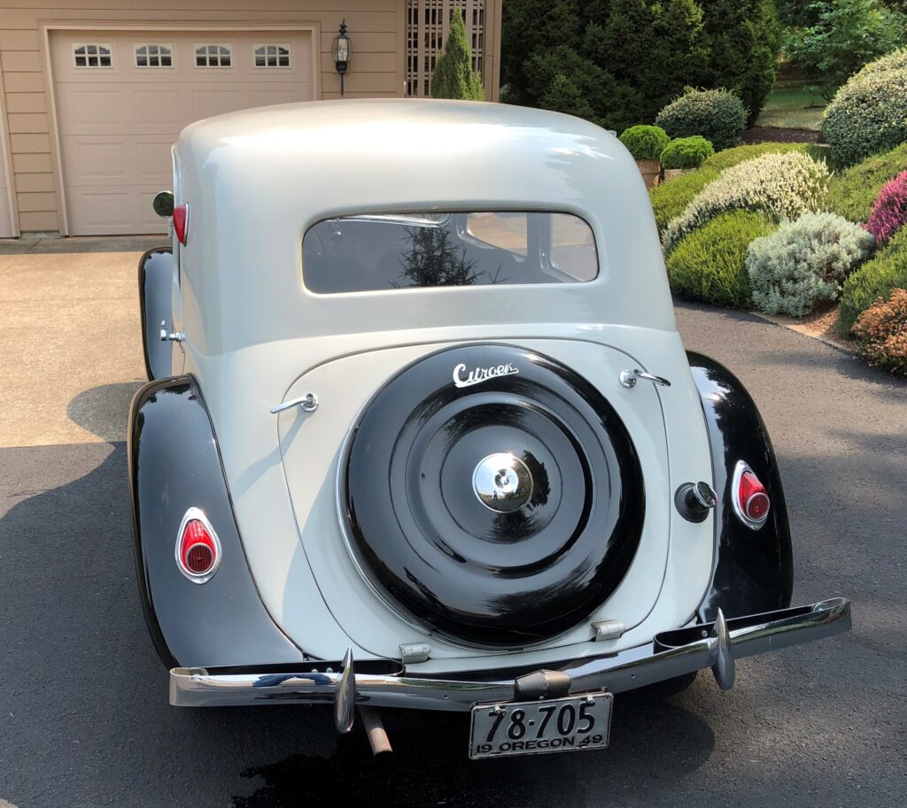
Below you can see what my car would look like with a wheel instead of a trunk:

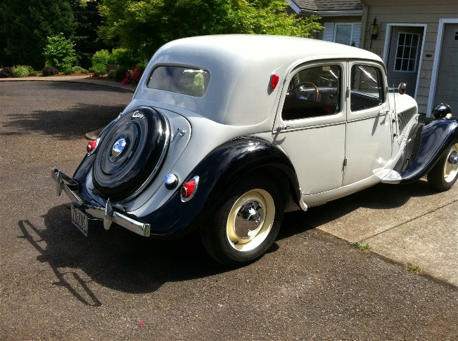
And, for comparison what my car looks like BEFORE the conversion to wheel:

Picture  dates from 2007

The trunk hangs from the part of the body directly under the rear window.

On a wheel version, there is still a section of sheet metal under the “kink” in the sheet metal that is under the window.  That is completely missing from the trunk model.

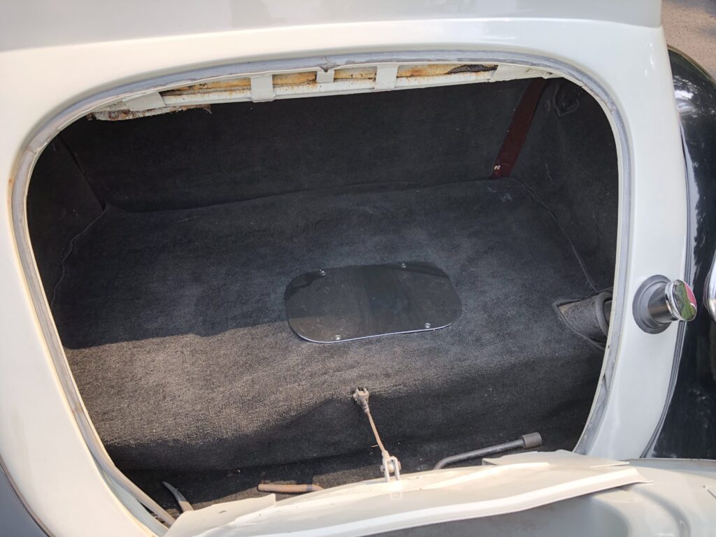
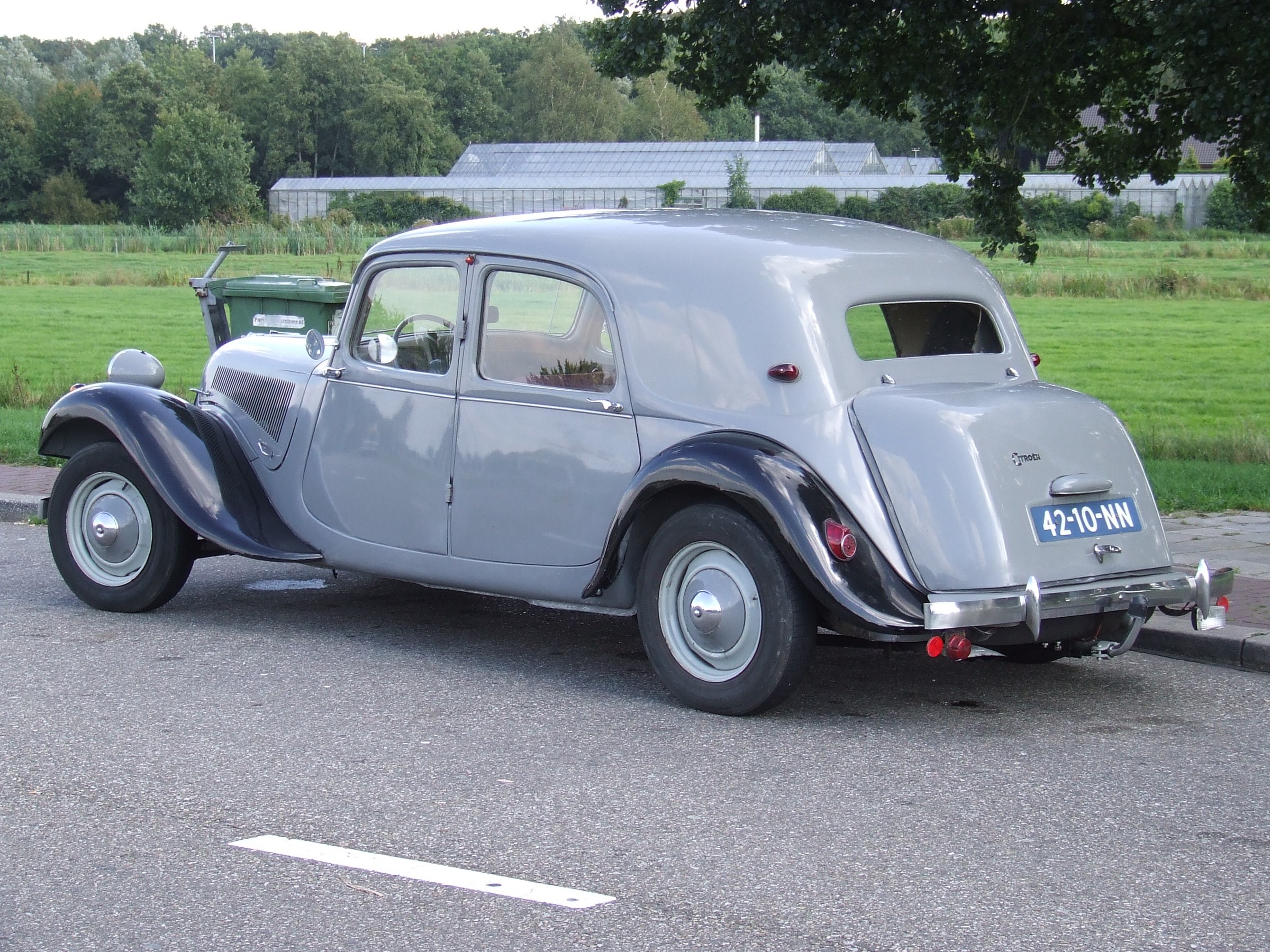
And the underside in terms of sheet metal runs all the way through (gray) , including under the trunk lid (gray lid with black wheel cover).  This should be constructed anyway, and connected to the existing trunk floor plate. Everything under and behind it has to be removed so also the spare wheel well and the existing extra extension of bumper brackets and the ‘standard’ extra bolted-on sheet metal.

The fender points L and R are connected with a piece of sheet metal, under the fixed body (grey). This sheet metal part is still readily available as an aftermarket part.

THE APPROACH – is planned for mid 2022, after finishing the ID20 –

LPG tank out, gasoline tank out from under it.

OUTSIDE THE CAR:

First, a fender edge is made that follows the exact shape of the trunk lid of the wheeled version.   Then a sheet metal edge is made that fits in the hole created when removing the existing boot lid.  After that, it’s going to be a lot of fitting and measuring.  Temporarily the new sheet metal part with sheet metal edge for the lid is fixed with U-strips instead of the lid.  This makes everything a lot easier to handle.

ON THE CAR:

Next, the new sheet metal part is fixed in place and secured with small MIG dots.
Then mark where the excess material needs to be removed.
Grinding off the new sheet metal, and
everything to size, strip the edges and reposition the new part
Welding the new part in place, measurements and dots.
Weld in the 2nd round of dots.
Then fit the valve.
Mount the valve and fix it (by MIG welding the dots to the edge of the plate).
Then weld the plate to the body with a few spots at a time, and keep cooling with air.
Weld in further and further until everything is welded in, and wait and cool with compressed air.
Then without heating grind flat with flapper wheel and
Then use fiber 2-K waterproof filler to seal the weld and immediate area.
Then bondo over the whole, and
flush with 60 grid.
Filler primer over it,
spray contrast on,
manually level with 200,
then spray again contracts
and flatten with 400 etc.
Remove pinholes and again after
Contrast spray and sand with 800.
Waterproof sanding with 1200 and
then to the painter.

CAUTION to use light gray filler, bondo etc. of the same hue/color, this will save possible misery afterwards when spraying.

error: Content is protected !!