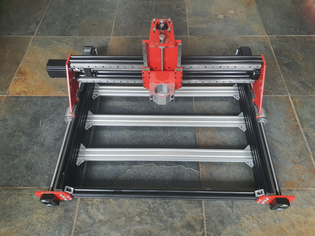
The Indymill’s Z-axis uses a lead screw by design , and not a ballscrew as I would like. But- that will be changed later.
For now, the lead screw solution will be OK because I will first build the Indymill machine and use the 500 Watt DC engine I already have for my CNC3018 setup.
The leadscrew of the Indymill is an 8mm leadscrew with a brass nut mounted in a 3d printed part that is mounted on the vertical rear of the Z-plate.
And- the drive stepper motor is mounted hanging on a horizontal plate on top of the Z-plate.
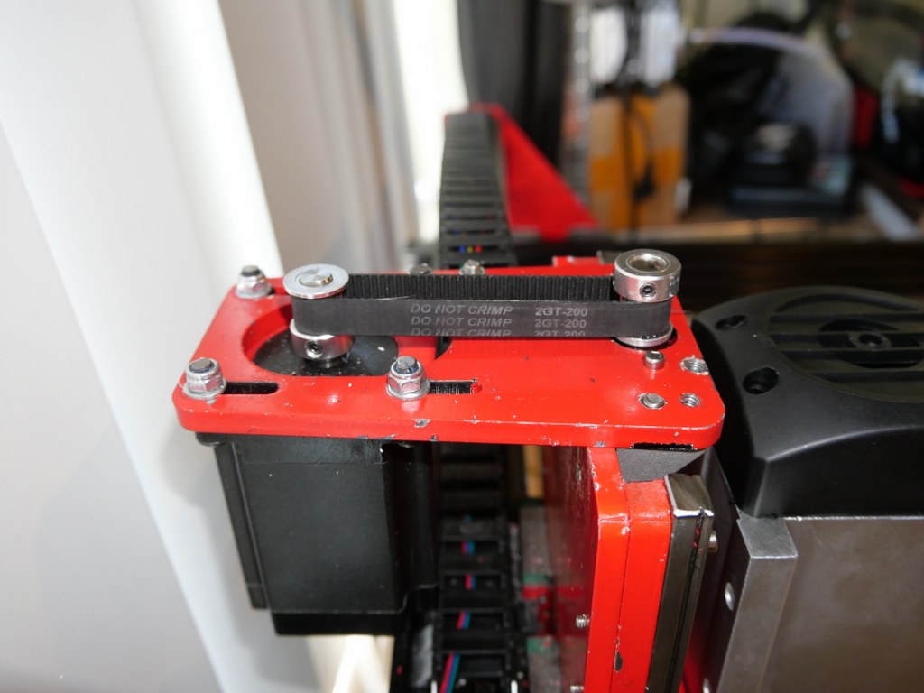
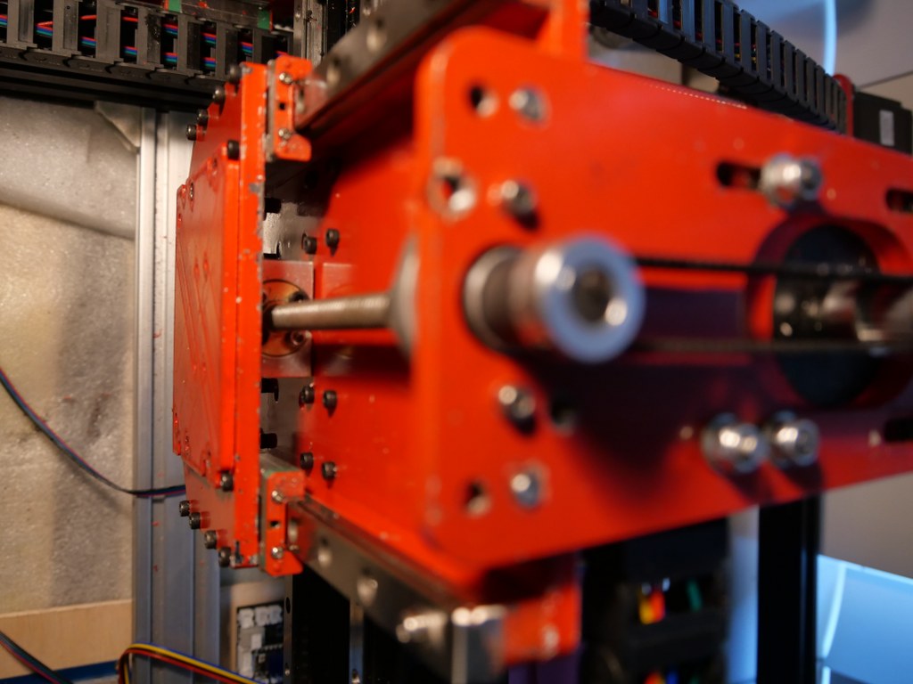
The required motion is exchanged to the leadscrew with a pair of 8x10x22 treehed wheels that are coupled with a GT2-10 mm wide 200 mm long belt.
The change I made to the original setup is to use an original 8mm lead screw bearing on top, under the horizontal plate.
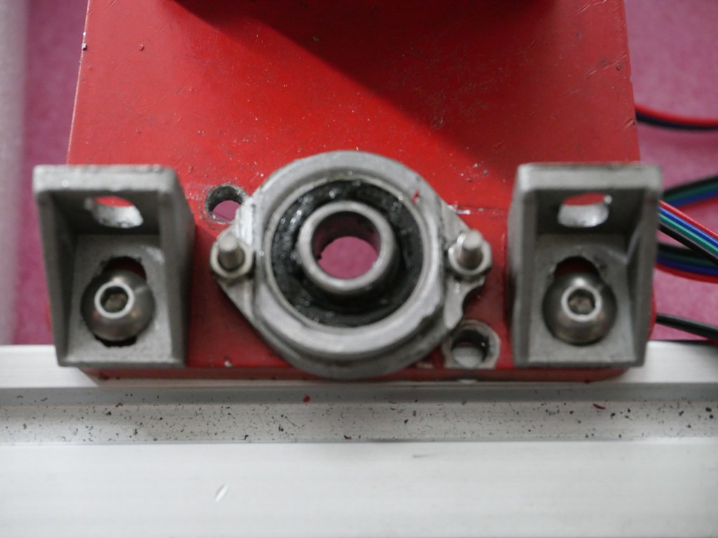
I did not particularly like the original setup with an 8mm bearing in a 3d printed holder, and an 8 mm lockup ring under and above this bearing.
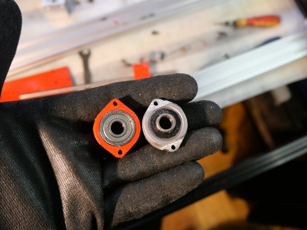
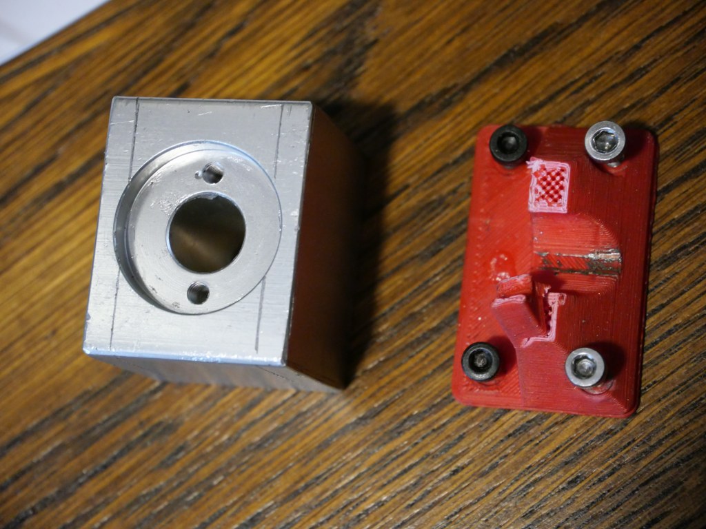
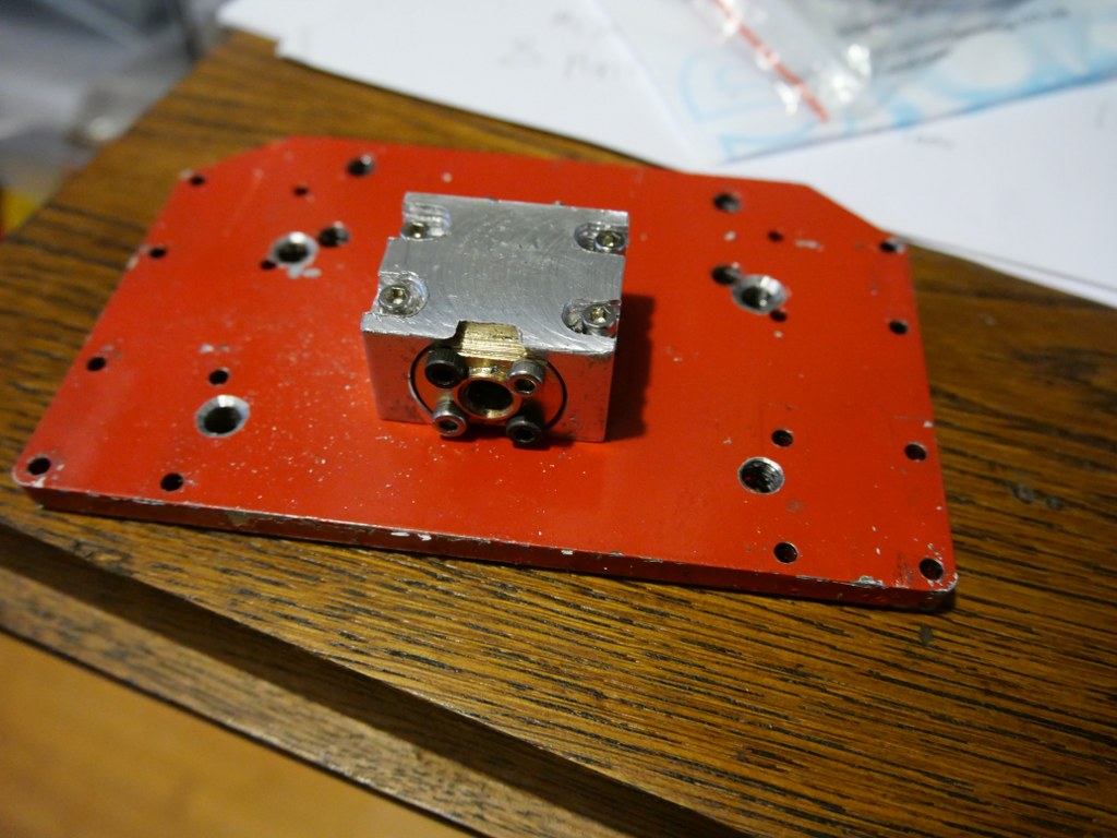
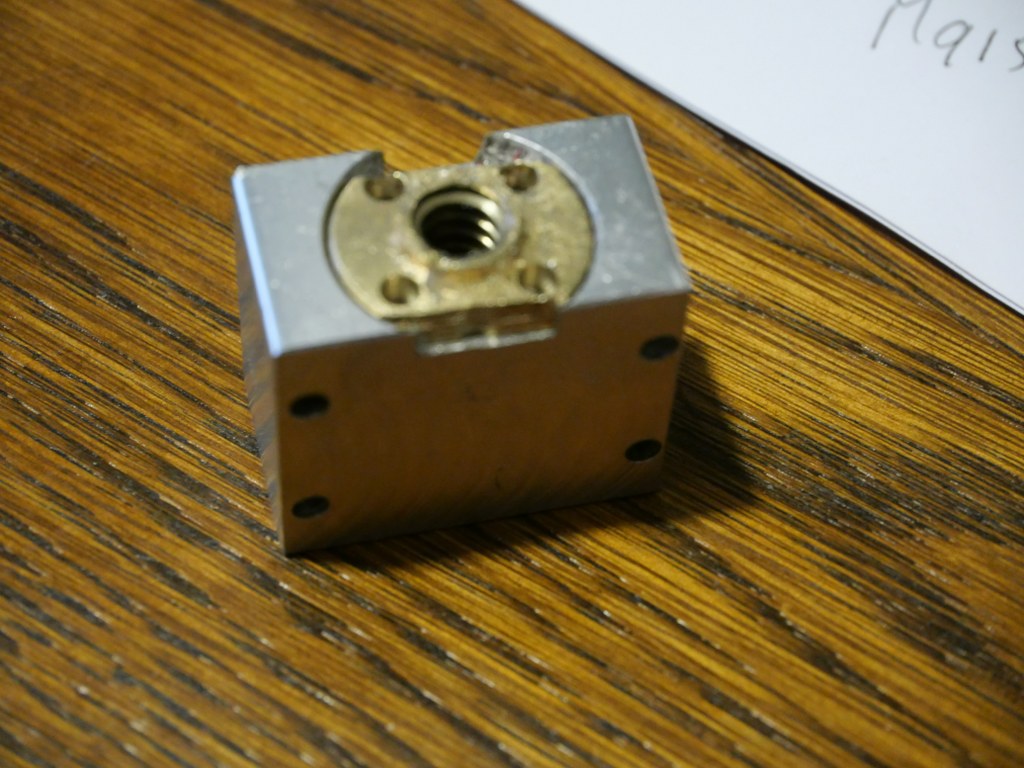
I had to machine the pro-bearing to fit the Indymill’s mounting holes and get the threaded drive screw nicely centered.
