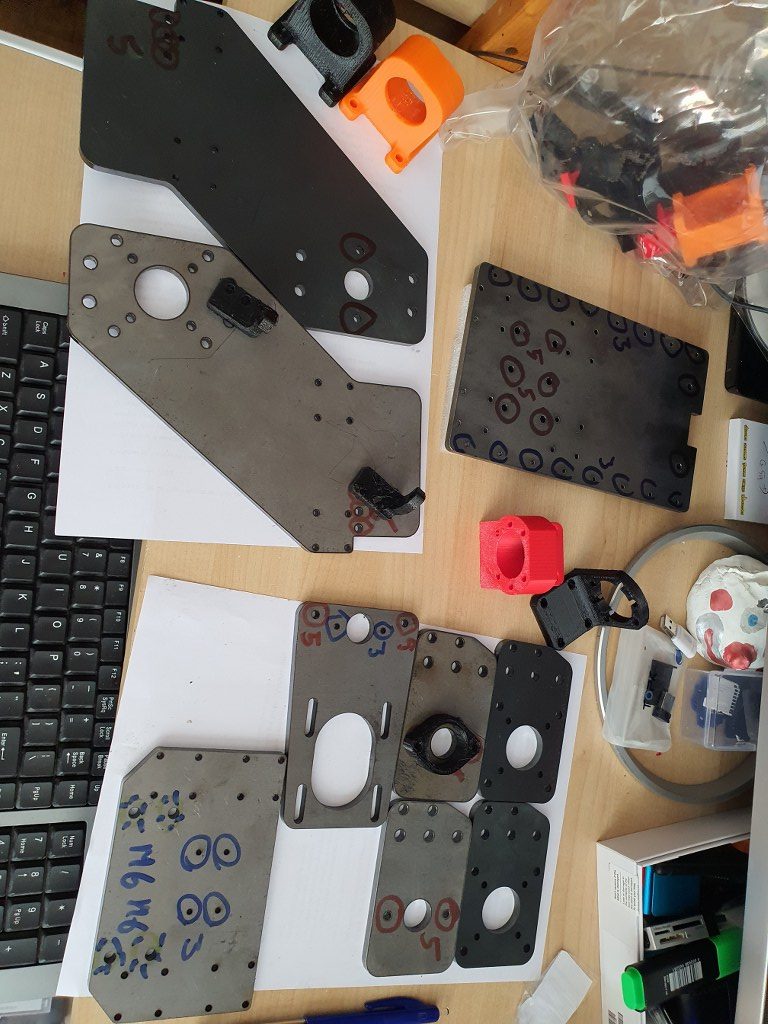
2021 05 13: Yesterday I received the iron plates for my Indymill from Nikodem Bartnik, and it was all very well packed and quickly delivered!
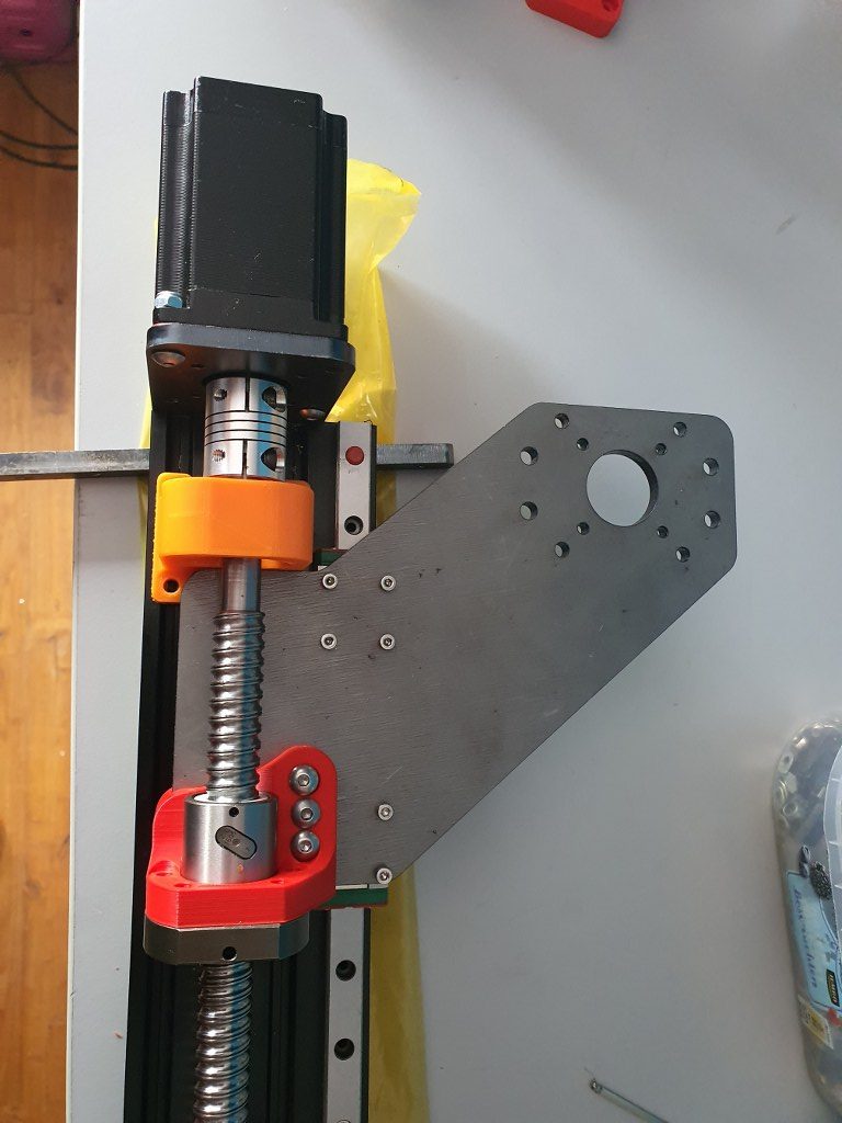
As I always do on any build, I first check the separated axis for best fit and possible improvements. I started with the Y-axis. In the below picture, the left side of the macine is shown, being the left Y-axis. The rest of the machine is not yet attached.
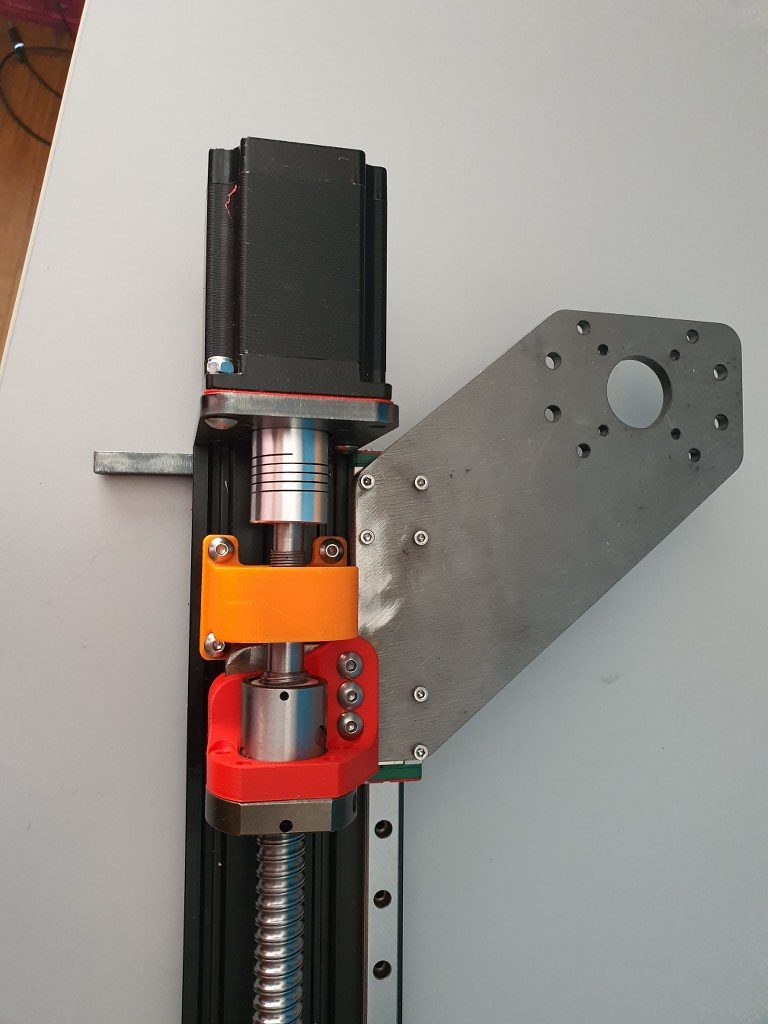
This is how I started with the original design. Ball bearing block (orange) and screw mount (red) are both 3dprinted here.
The Y-axis is somewhat limited in its drive towards the rear of the Indymill CNC machine, due to the bridge plate for the X-axis. This bridge plate is blocked in its movement towards the rear because it hits the bearing block (orange part) that holds the ballscrew in place. By removing a small and unused part of the bridge plate, the movement can get about 6 cm extended towards the rear. The pictures are attached to this post, please see how I made this.
Maximum movement towards the rear (top in the picture) due to a removed piece of the bridge plate
I used the plasma cutter to cut the parts out of the 6mm steel plates and after this was done, I used the lamel grinder to make it smooth. Although I used a guiding rail for cutting, the power was apparantly a bit too much so it is not a very beautiful cut… -) No worries because all still fits very well.
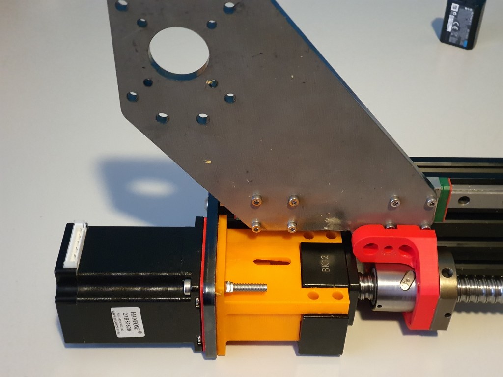
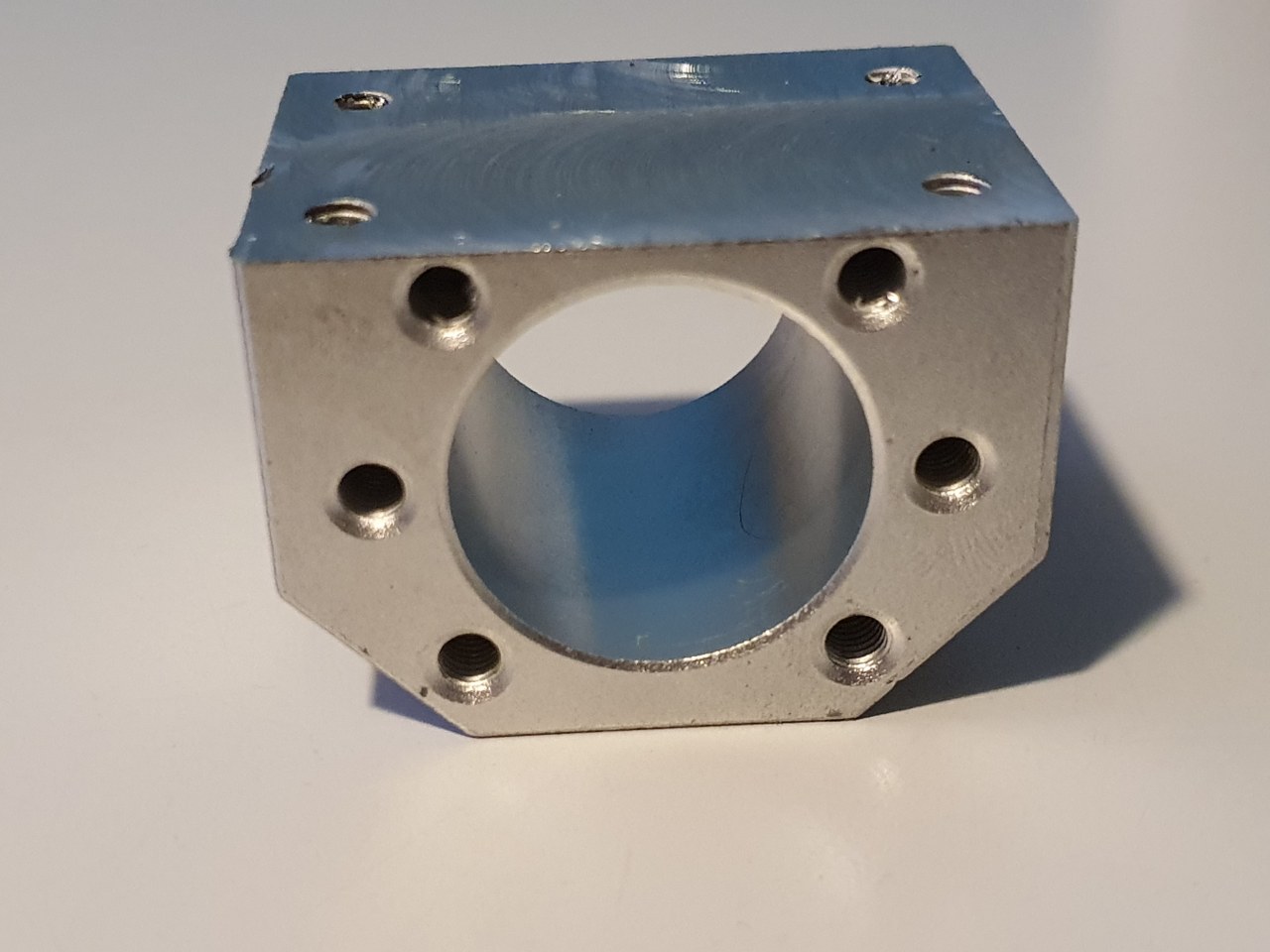
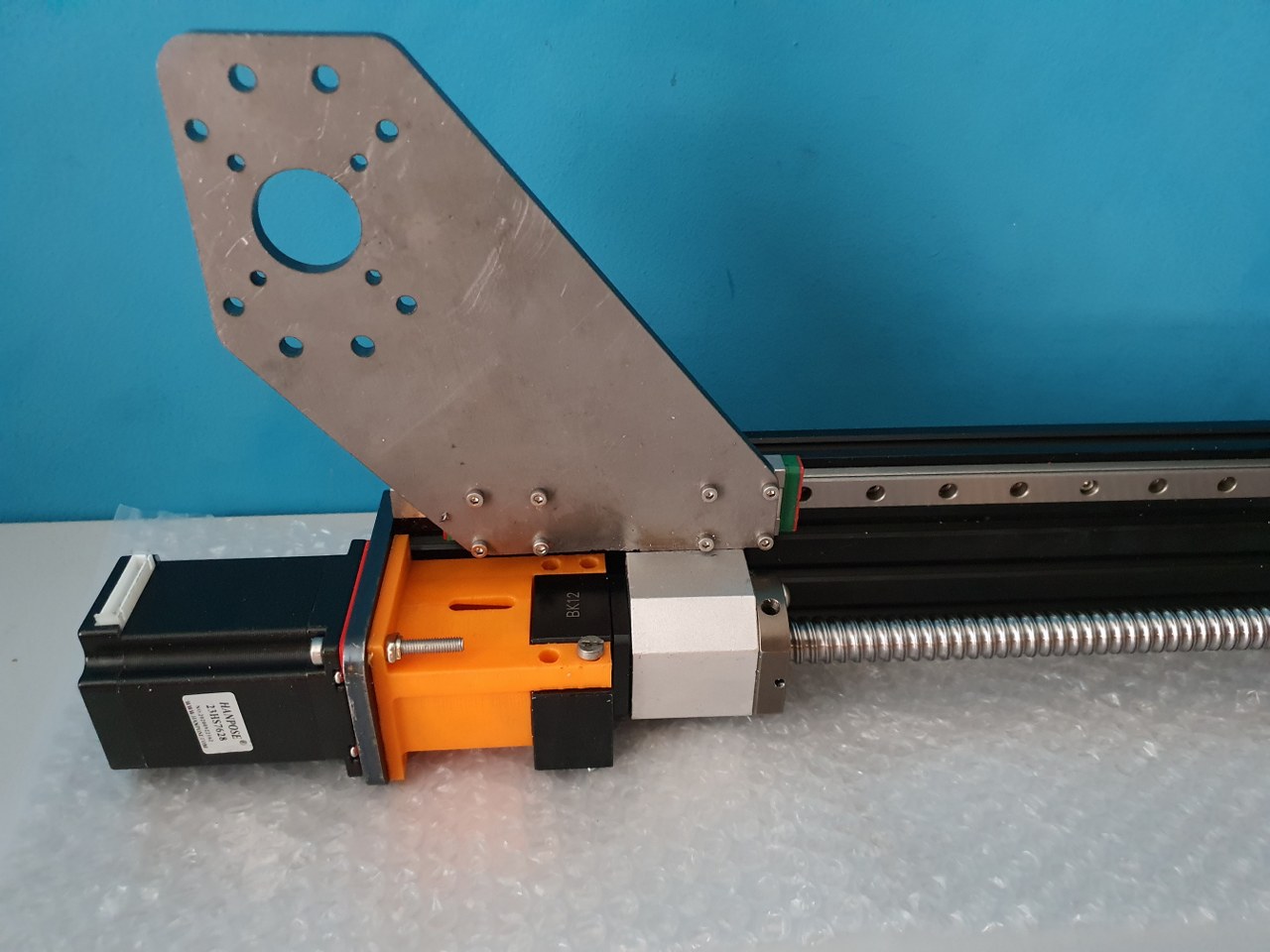
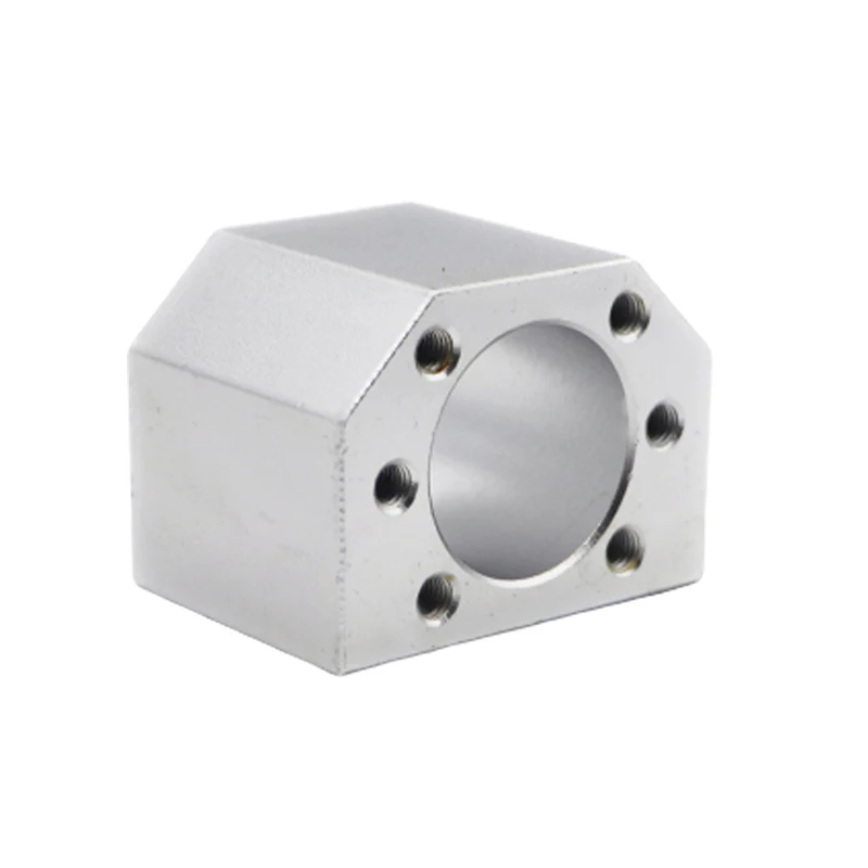
BK12 original axial bearing (black) for 1605 ballscrew and -nut (red) with Nema23 holder (orange) with an attachment for the original BK12 bearing, both placed on the left Y- axis of the IndyMill CNCAn original nut holder for a 1605 ball screw nut, machined down on my manual mill to fit the Indymill’s Y-axesThe nut holder in place on the left Y axis
I am in the process of developing a router for my plasma cutter, since the cutter works very good but it will be way more effective once I can machine my designs with a router for this cutter.
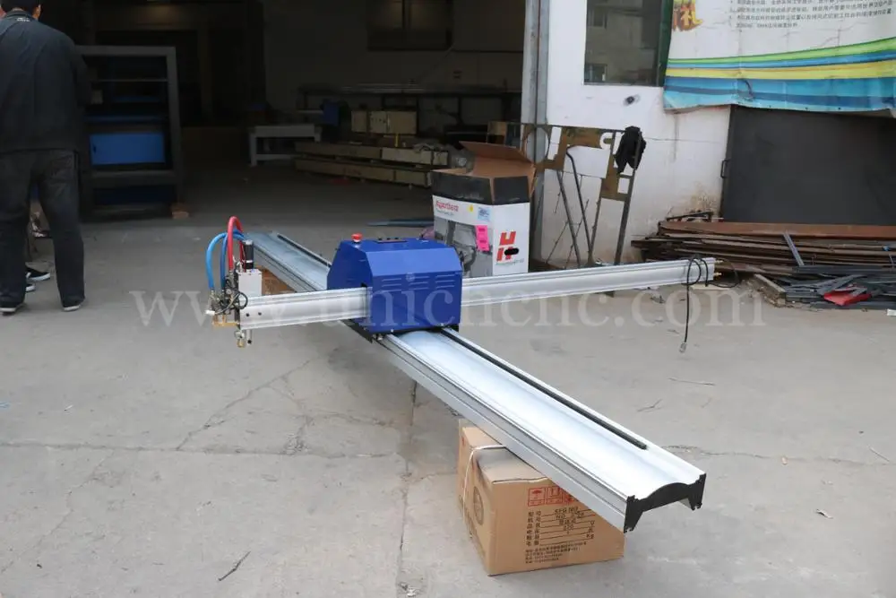
Example of a very big X-Y design for a Plasma Router on Aliexpress
My design differs from others because i will use only existing affordable parts that require no additional machining.
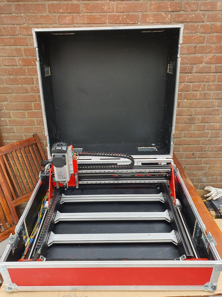
Firstly, you would need a cutting table with a maze where you can put your steel on, when cutting. This maze will be enclosed with a steel box so no cutting debree will be thrown around. Around the box a set of aluminium or steel profiles will be mounted on which the wheels for the X or Y axis will be built. From here on, a normal router setup can be made.
The plasma head will need to be adjustable in height but does not neccessarily need to be CNC movable. Just a manual knob to move it up and down a little will do.
So, only 2 axis are to be made with CNC.
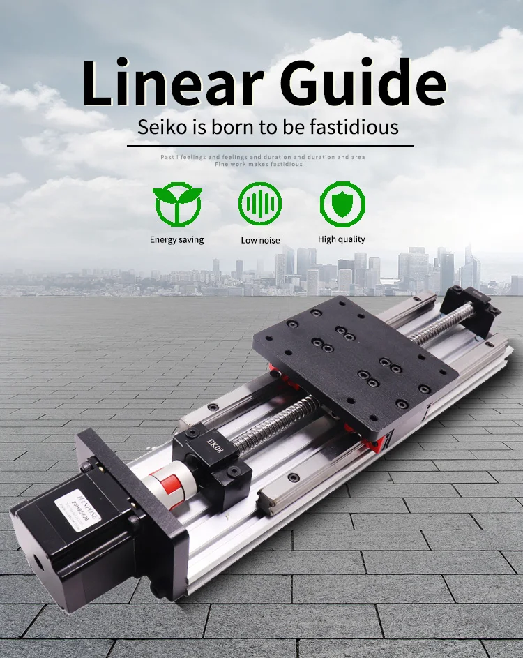
For the Y axis I will use a complete accessory from AliExpress with ball bearing 1604 and an effective way of 600mm, including a Nema23 stepper motor.
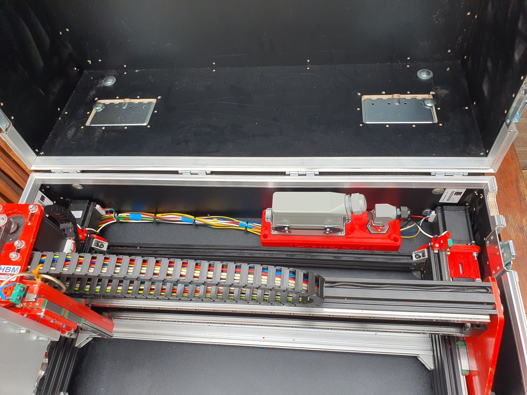
Y-axis 1204 ball bearing screw drive, NEMA23 stepper motor and dual linear rails. This will move the plasma head left and right. I might use something a bit simpler that this…X-axis on both sides of the box that will move simultaneously forward/backward with steppers mounted in series, the Y axis will be mounted in between.
The plasma cutter ‘head’ will get a fixed (but a bit vertical movable) mount on the mounting plate of the Y-axis.
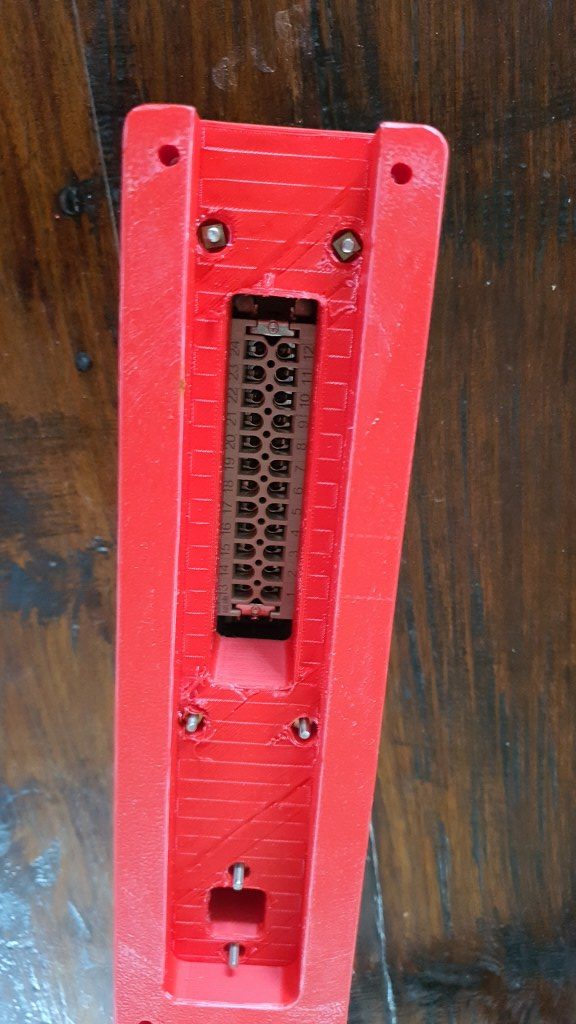
Magnetic break-away torch mountAnd the mount for the head of the plasma cutter
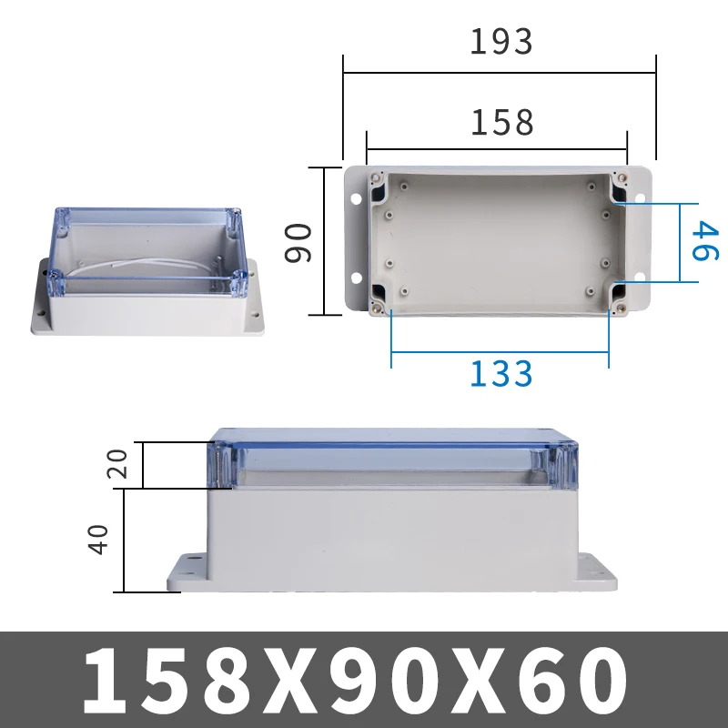
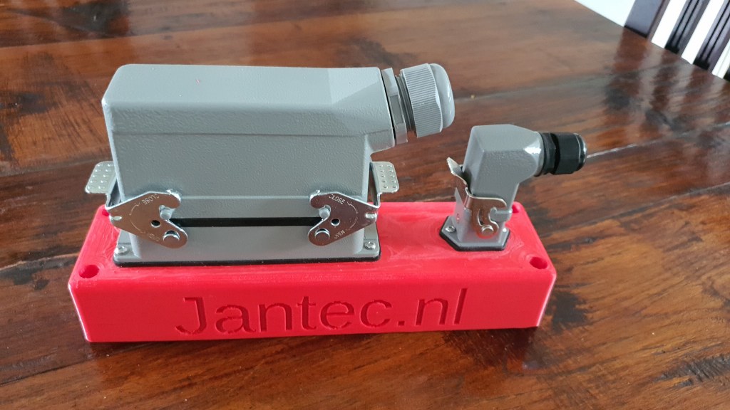
The electronics will be added at the front of the Y-axis in a 3d-printable box. (or you can buy a ready-made box HERE).
Electronics will be an Arduino UNO with standard GRBL shield, or THIS as a better all-in one solution, including local router managing. At the beginning and end of each axis, a limit switch will be mounted. Switches, cabling and mounts are available on Aliexpress HERE and HERE.
Firmware for the Arduino comes from the widely available GitHub and the GRBL community. GRBL software is available for Windows PC and MAC as well. Designing can be done in any way, and the most simple way will be the online Cad solutions like Tinkercad .
The power supply for the Plasmarouter will be a 24 Vols 8 Amps portable power supply like THIS one.
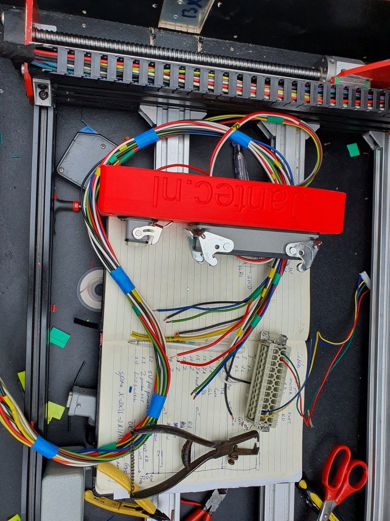
It took a lot of time to get it all tuned, as the 3 axes act entirely different due to their different inertia. The weight that is carried is obviously higher for the Y- than for the X axis. And the 4 kilogram weighing spindle engine made it pretty difficult to get the Z axis tuned.
The resulting config file is provided in this post. Use this with caution, since every machine is different, and the used stepper motors, cabling, steppers and PSU all have influence on the CNC’s behaviour and thus on the config settings.
To have the original Mellow FLY TMC2209 drivers work with sensorless homing, set the underneath dip switch to ON
(Diag pin will then be connected). It took me some time to find out that this is different than other TMC2209 drivers, where the Diag pin is activated by jumper settings on the motherboard. No idea what happens when you use non-Fly TMC2209’s on the Fly board, but I expect this will not work for sensorless homing.
What I experience on the Y axis is that if you have real problems with homing or skipping steps, the steel Y carriage plates may bend and cause a non-square Y carriage that will never align any more. I repaired this but preventing is better.
Since this setup with sensorless homing never gave me good speed ratings, I disassembled this setup and continued with endstop setup. If you want to know how to setup sensorless homing with reprap, please look at my sensorless homing setup on my dual carriage 3d printer, where this works perfect!
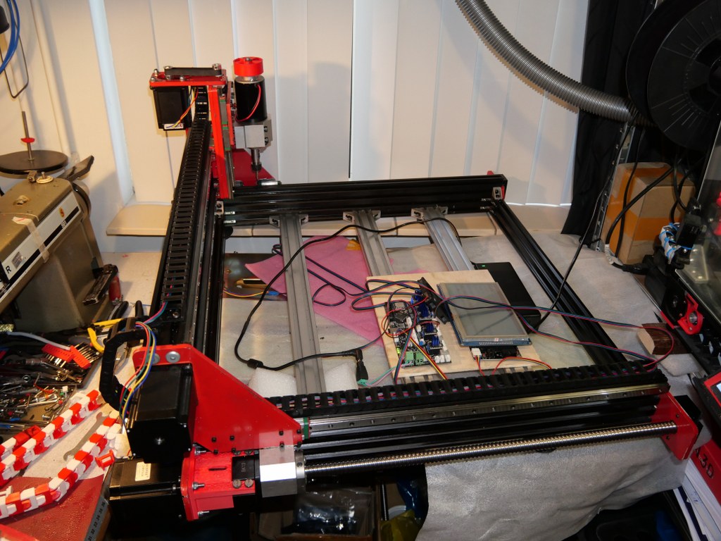
This is my test setup for a 1.4 RAMPS shield on top of an Arduino Mega with TMC2209 drivers, optical endstops and individually homing of dual Yaxes PLUS an LCD that shows the exact XYZ locations anytime.
Firstly, I must admit that this option was initially NOT on my list bacause I felt this was a pure hobby-like option. BUT- as my requirements list grew and other options got less and less, I ordered a Ramps 1.6 shield and plugged one of my Mega2560 boards under it. Then- the search began to get a working fork of GRBL for arduino that both accomodated the Mega 2560 and my requirements list. On this list: GRBL, Squaring my gantry, LCD with useful data, Handwheel connection, Preconfigurable buttons on the handwheel (stop, define as zero, probe here, et cetera). The fork that does this all is: GRBL-Mega-edge. The last comment is of April, 2020 and the fork was updated last in 2019. But- it works straight out of the box and the documentation is very well maintained.
Since it works under the Arduino IDE and has its own library, I foresee little problems in the future. Everything is freely configurable and it might even be possible to put an Arduino Due in place of the Mega2560 in this setup, with some tweaking of pins and speeds. And- tweaking is required for the hardware as well. The Ramps boards were never designed for 24 Volts, so this needs to be taken care of. One might of course use 12 Volts and use external driver modules, but I intend to keep everything very small and make use of an external PSU, and a small handwheel-like box for the Mega2560, Ramps, drivers, LCD, buttons and handwheel knob. By the way: For getting my designs I already had from my 3d printer background towards the CNC I bought Estlcam (CAM program). This really does a great job at converting it to Gcode and sending it to my Grbl- Mega 2560/RAMPS setup.
Afterthoughts 2021-06-22: When connecting Estlcam to the Mega2560 and RAMPS1.6 shield, Estlcam can program the RAMPS / Mega2560 configuration, including dual X and Y axis. This works straight out of the box including endstops. Actually this is easier than first compiling GRBL on RAMPS with Arduino’s compiler. BUT- it seems that autosquaring does either not work or I did not install Estlcam’s options correctly since the endstops on the dual axis appear to function in parallel instead of indicvidually per axle.
24 Volts connecting is not possible on a RAMPS shield just like that. I removed D1 and powered the Mega2560 with a 9 Volts PSU, and the shield seperately with 24 Volts. For the Arduino DUE, dedicated RAMPS boards are already available (Smart ramps that compensates for the 3.3 volts in/out Voltage of the Arduino Due)!.
Another option for Estlcam is to program the Mega2560 without RAMPS shield and connect everything directly to the Mega2560 with jumpers. If this is done, Estlcam will do the bare programming of the Mega and Estlcam can steer almost everything. Since I bought a license for Estlcam I will, at a later stage, try this as well. SEE THIS POST
The Estlcam software is a very well working all-in one solution for CNC machines.
The software has the capability to work with many hardware providers of driver boards like f.i. a simple Arduino mega.
BUT- working with add-ons is limited. The Ramps shield configuration is supported but not with individually homing of any axes. However, if you let Estlcam program the firmware of the Arduino Mega, everything works out of the box. BUT-you will need to connect all the wiring directly to the Mega.
In my search for the best working and most simple solution for driving the Indymill, this Estlcam configuration will be tested as well.
I am still searching for a shield that -in combination with Estlcam and an Arduino Mega or Due- will do everything I want/need like inclusion of 6-7 TMC2209 drivers on 24-48 Volts, dual axes on X and Y, dual endstops (high and low), mist/flood switches, LED WS2812 steering, emergency switches/power cuts, spindle RPM and on/off control, et cetera.
The MPCNC shield looks promising but there are others available, also.
The Tillboard shield is also nice, however I am missing some driver positions for my needs.
One of the nice things of Estlcam is that it will also work with all of the parallel and USB CNC boards that are available like all Chinese clones. I have some laying around and tried these, they all work well providing you will set it up correctly within Estlcam.
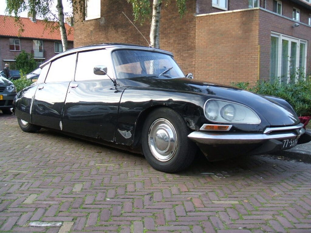
I bought the car early 2008 as a Berline version, in running condition.
But- after my initial maintenance and repairs the MOT proved a lot of problems with the chassis, lights, brakes, steering and so on.
So- the following month I repaired the car and made it ready for the MOT (In The Netherlands this is called the APK).
After this was all done, I restored the car best I could and used the car for about 5 years as my family car. We went on summer- and winter holidays with the 6 of us to Germany and France, a couple of times and I used the car mostly for the weekends since I also had a company car for work related traffic.
But- the weather conditions in our country caused quite some rust problems for the ID20 and I decided then to get the car more permanently in my garage and I bought me a more fitting car as private car.
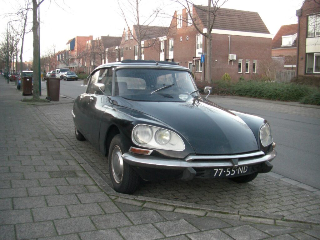
Later I restored the ID20 fully, paneled the doors, repaired the boot and the underneath of the car, longerons, front and rear fenders and so on. Basically, it was all plating repair.
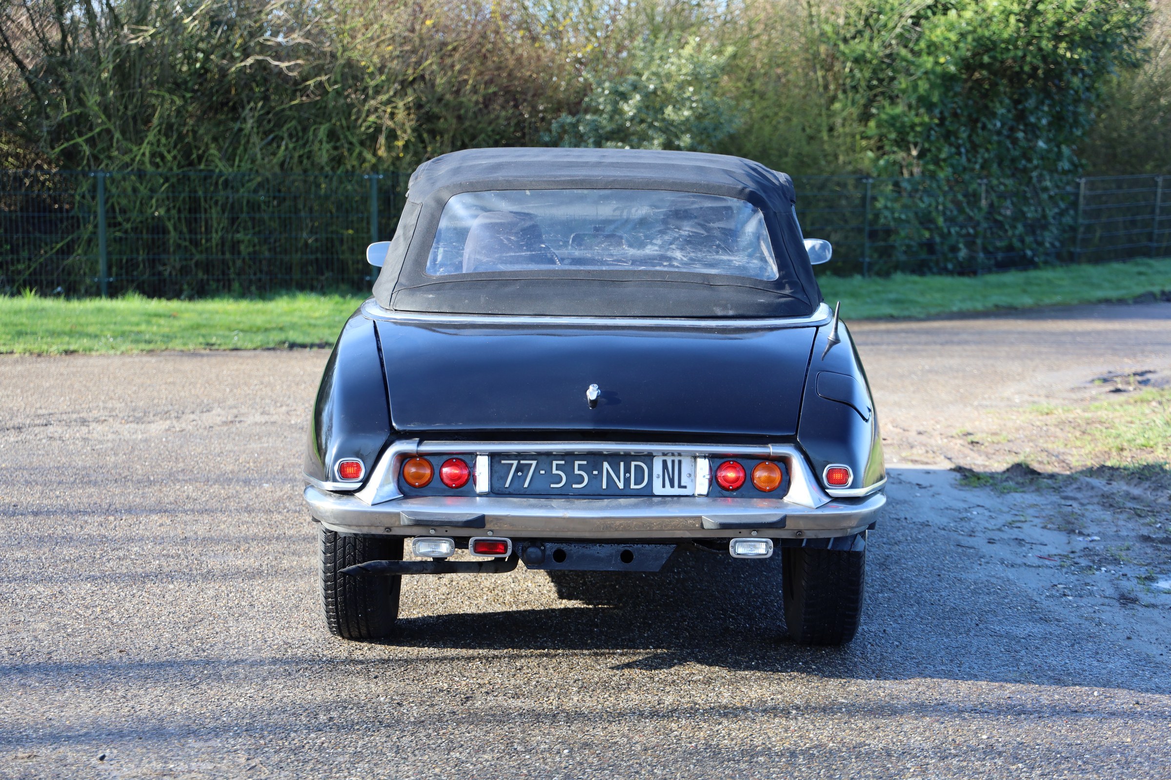
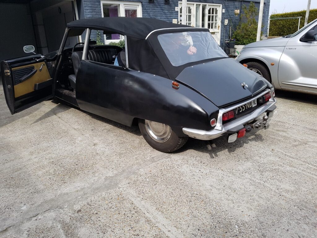
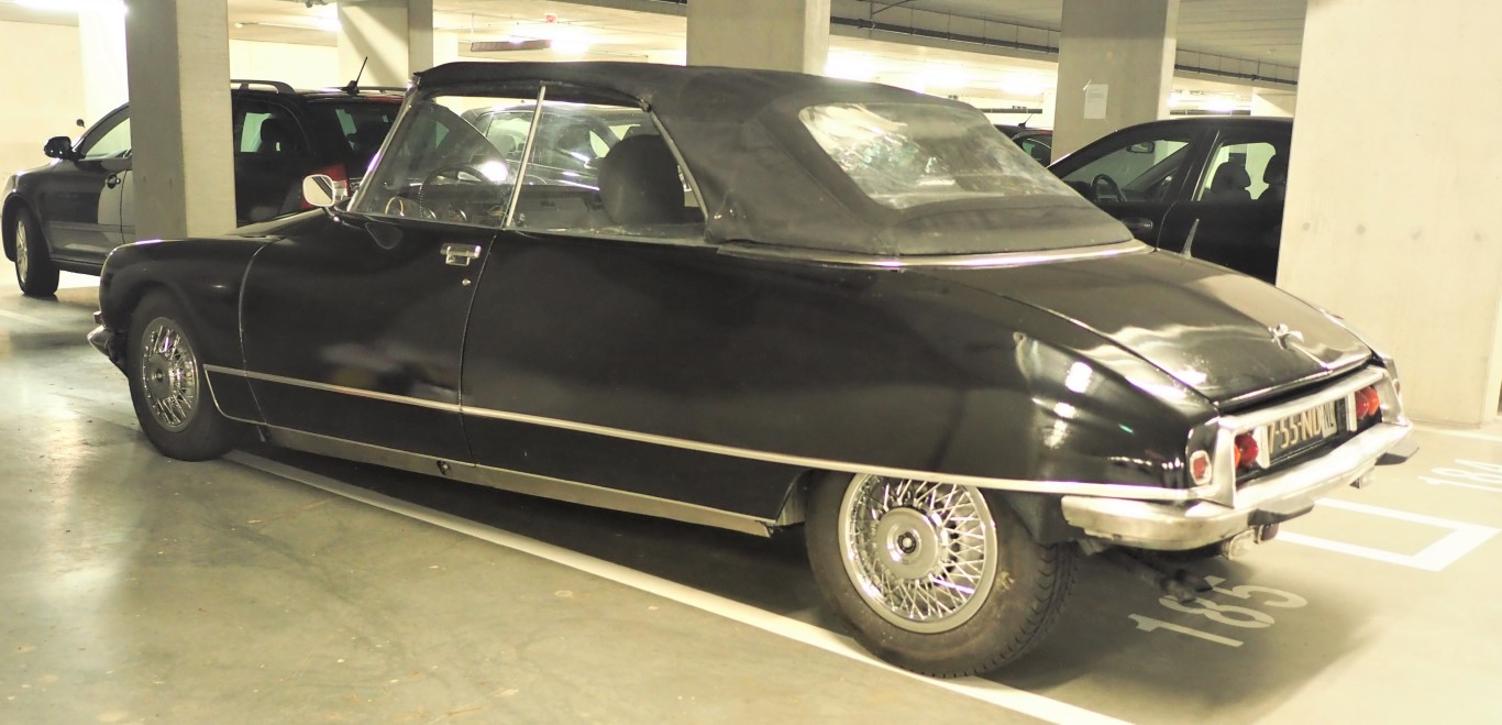
Then, in 2016, I decided to get the car rebuilt to converible by a well-known Dutch cabrio builder, Oord DS cabrio in Zwaag. This took a big part of the winter of 2016-2017. The rebuild also included a new license for the car, with an original Convertible ID20 model on the (Dutch) license at the same (old) license numbers..
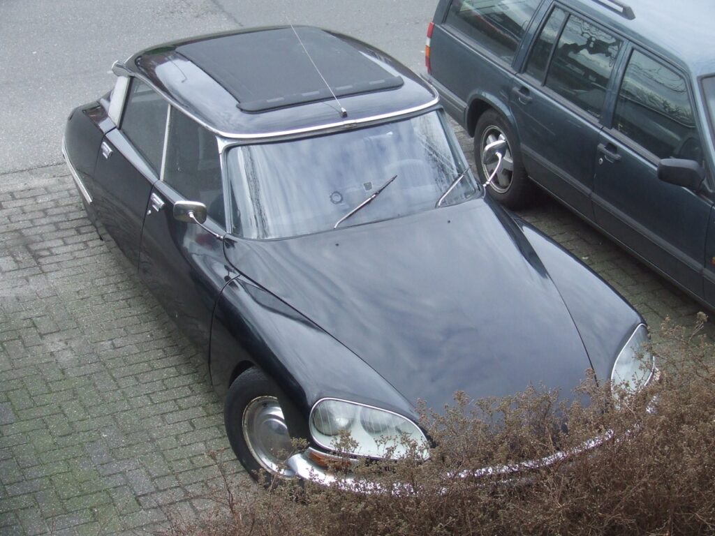
After this, I made a lot of improvements to the car like a new roof, from an early Audi 80, a refurbished HD pump, new waterpump and refurbished waterpump housing, new refurbished steering rack, upgraded the airco with new condensor and dryer, refurbished airco pump and so on.
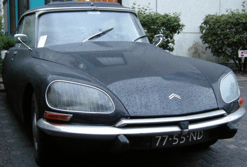
OLYMPUS DIGITAL CAMERA
And- right now (2021-9) I am taking the car apart again to get everything overhauled. Fenders, hood, boot, inside, chairs, bench, plating, engine, gearbox, drive shaft, suspension, steering, and so on. This is now more of a cosmetic overhaul BUT everything will be taken out, checked and overhauled if needed, and back in this winter. New leather is already underway at Eelco Schuurman’s shop for the ID chairs, new carpeting is araedy available and so on on the inside, the door panels will get renewed (also by Eelco Schuurman) , the car will get a nice new red paint and so on.
The process of this is also available on this website in ENGLISH
This website combines my previously created content into 1 website.
My name is Jan Griffioen.
Professionally, I deliver support to mid-sized and large companies on contractual- and ICT issues with my company
Due to my technical background I also develop, design, build and sell all kinds of technical solutions and products, primarily for individuals and small/mid-sized businesses. This varies from special LED controller projects for restaurants to designing and producing hundreds of 3d-printed special coupling tubes for a goat milk farm.
This site shows my technically based activities. Cheers!
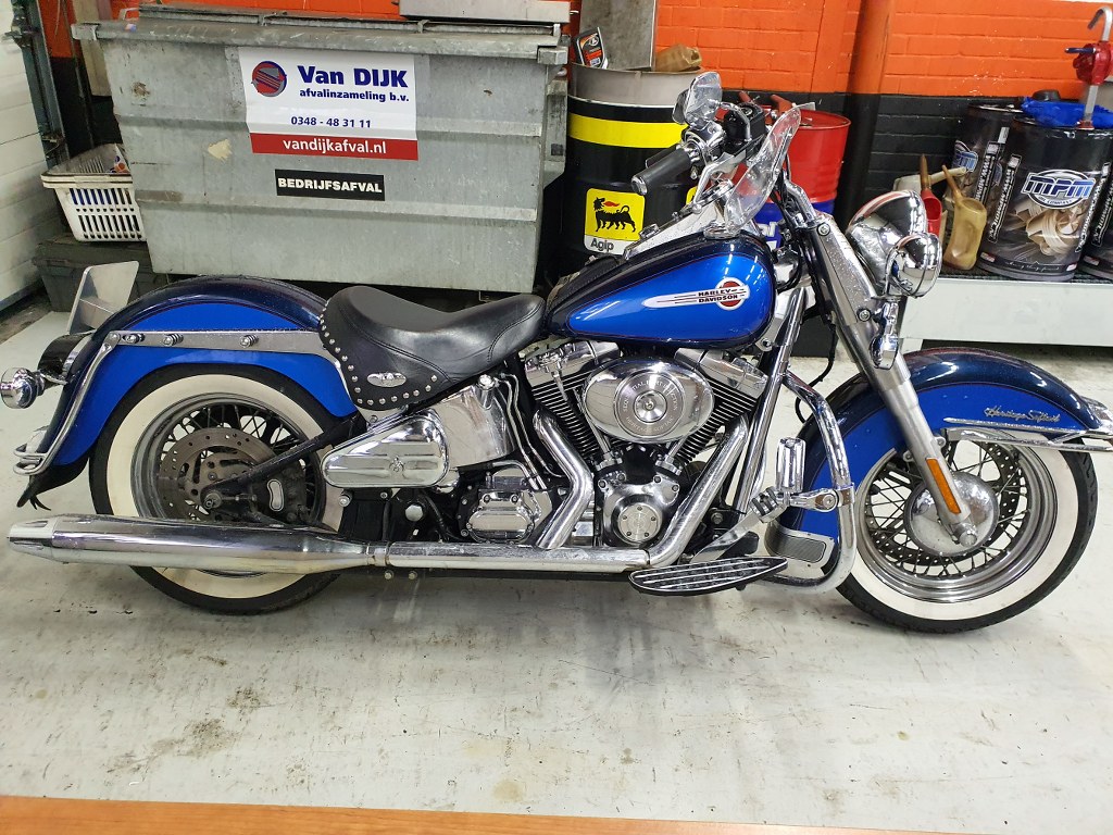
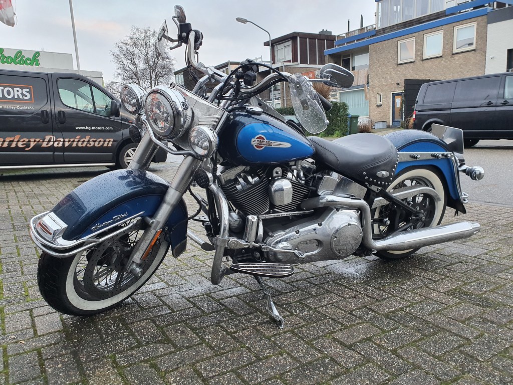
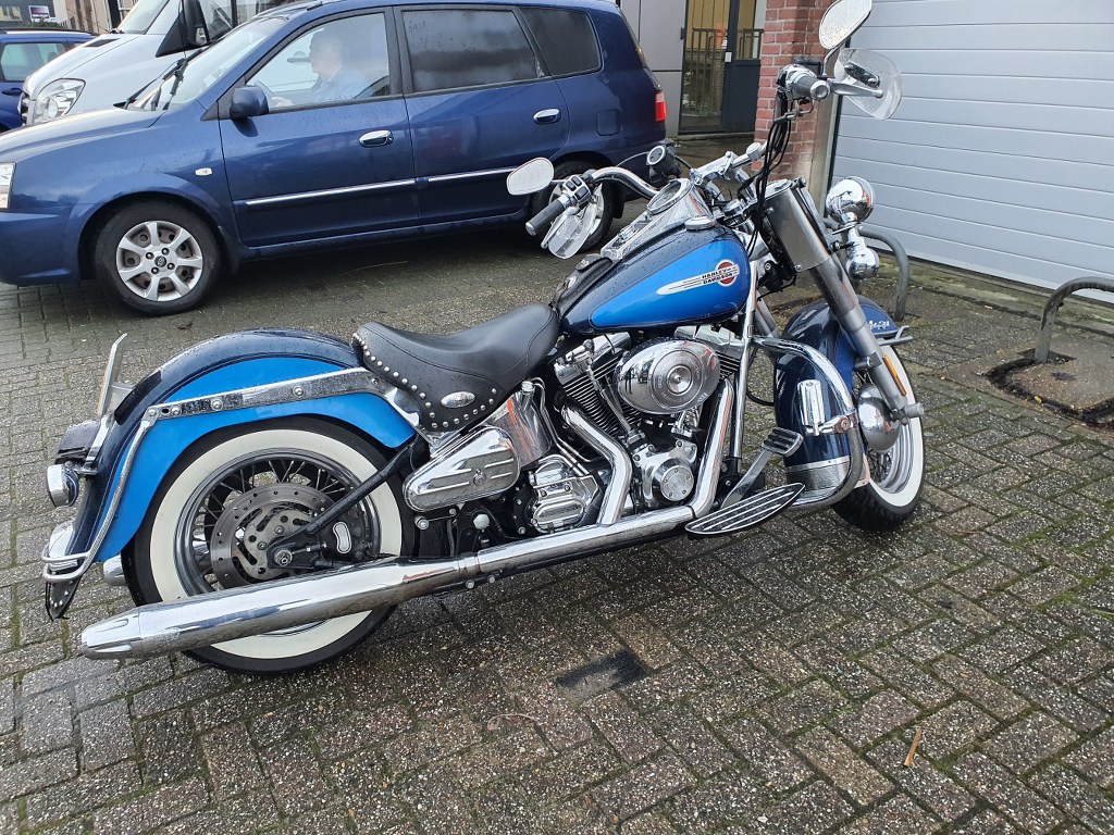
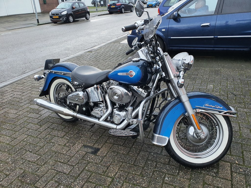
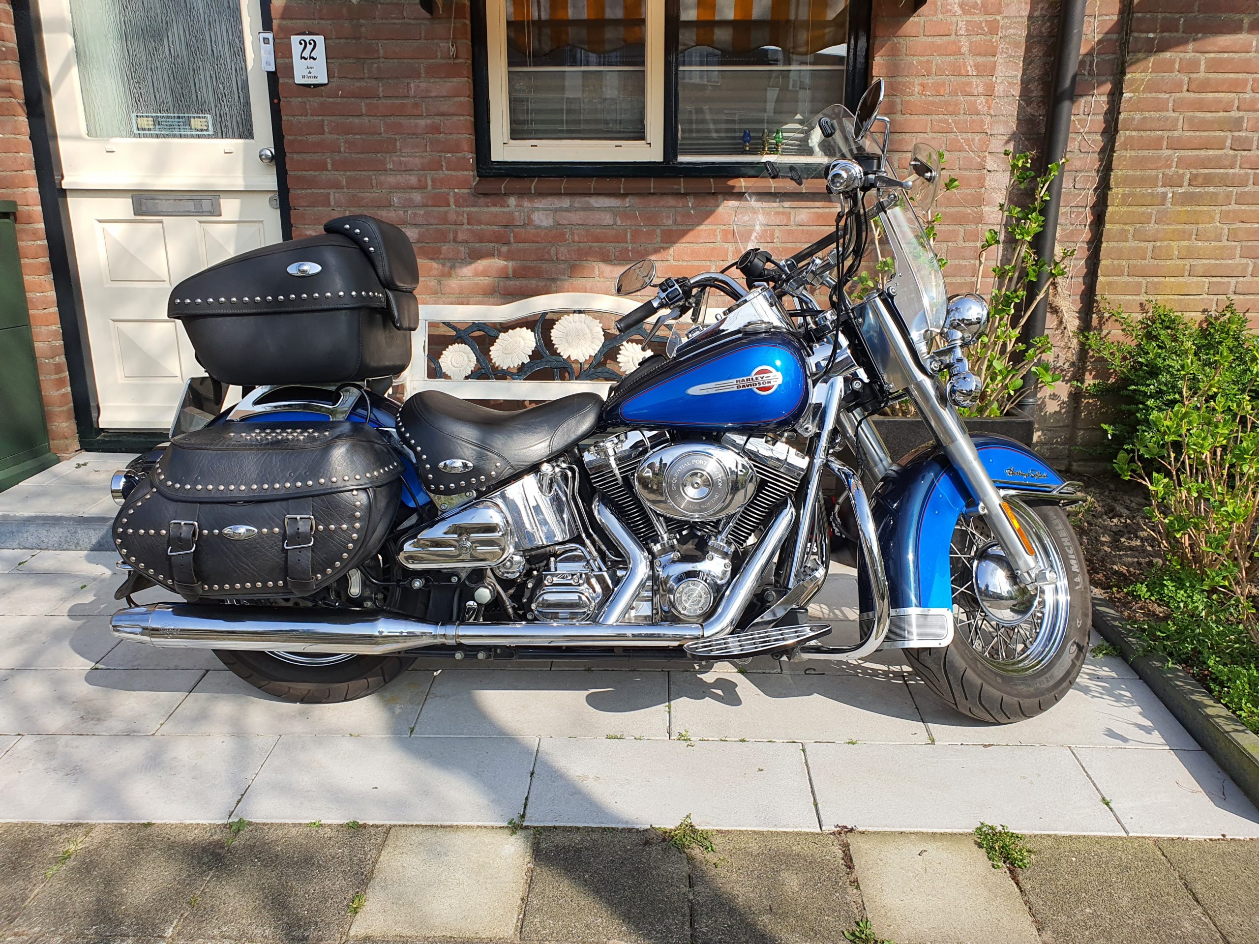
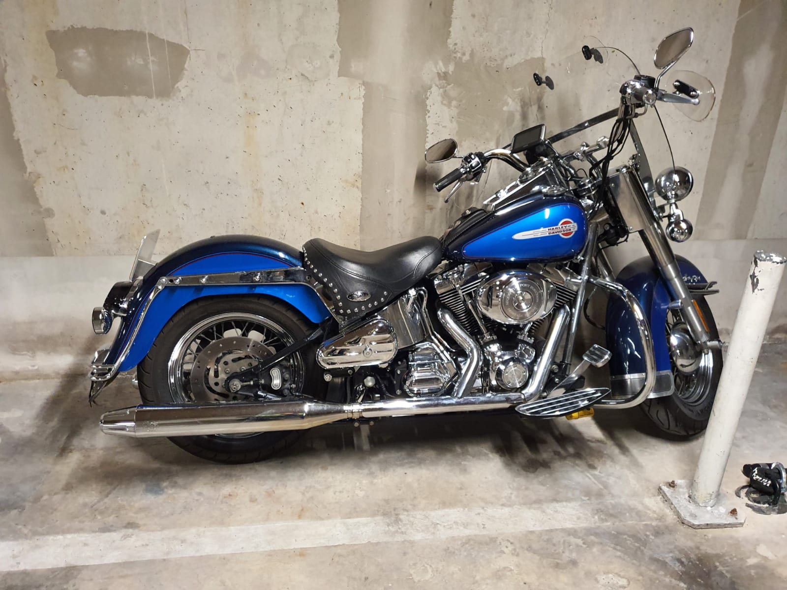
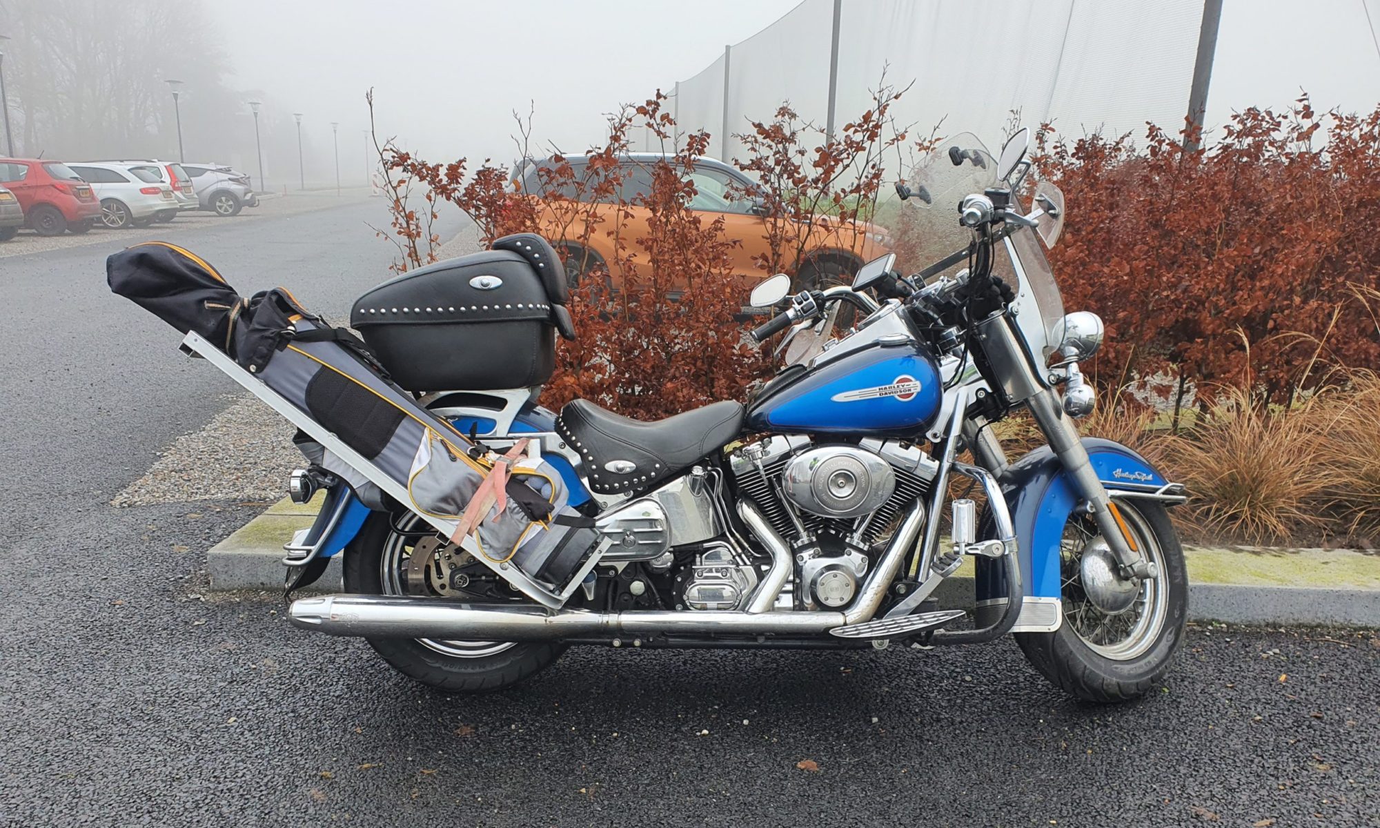
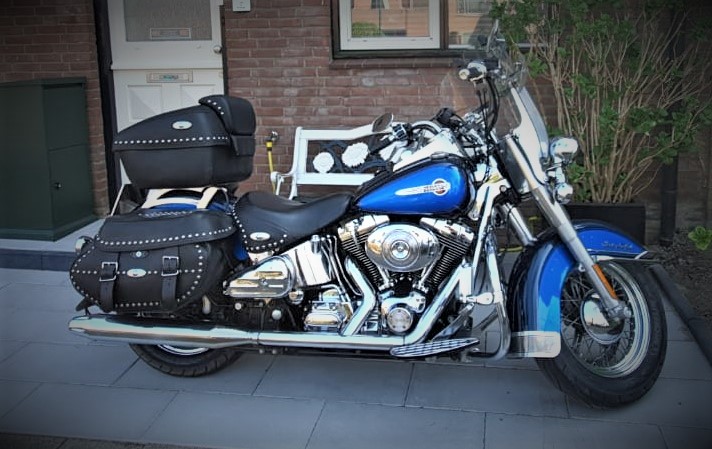
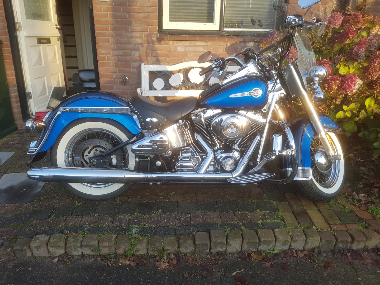
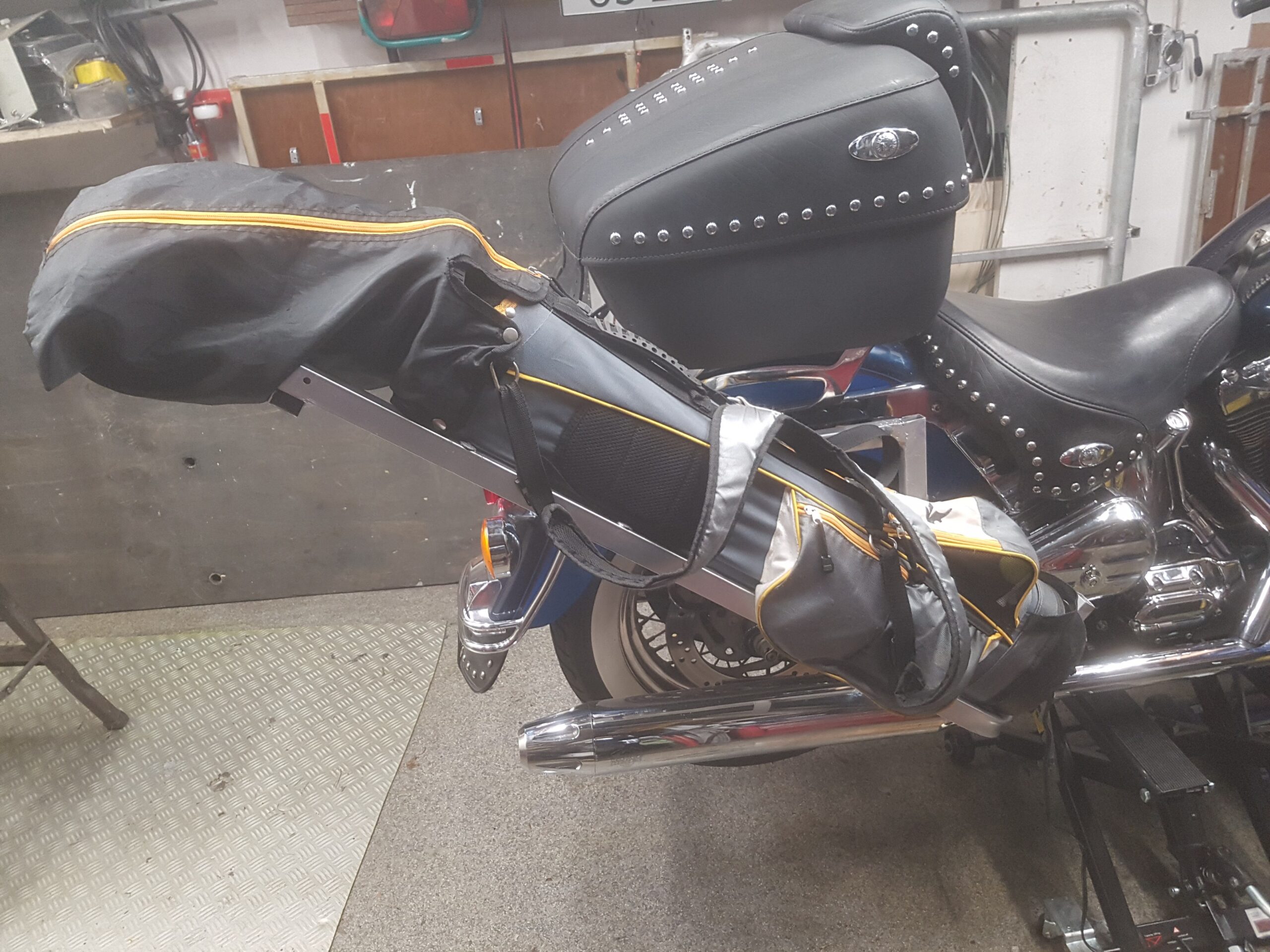
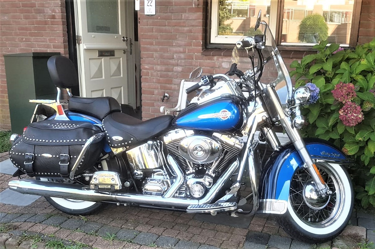
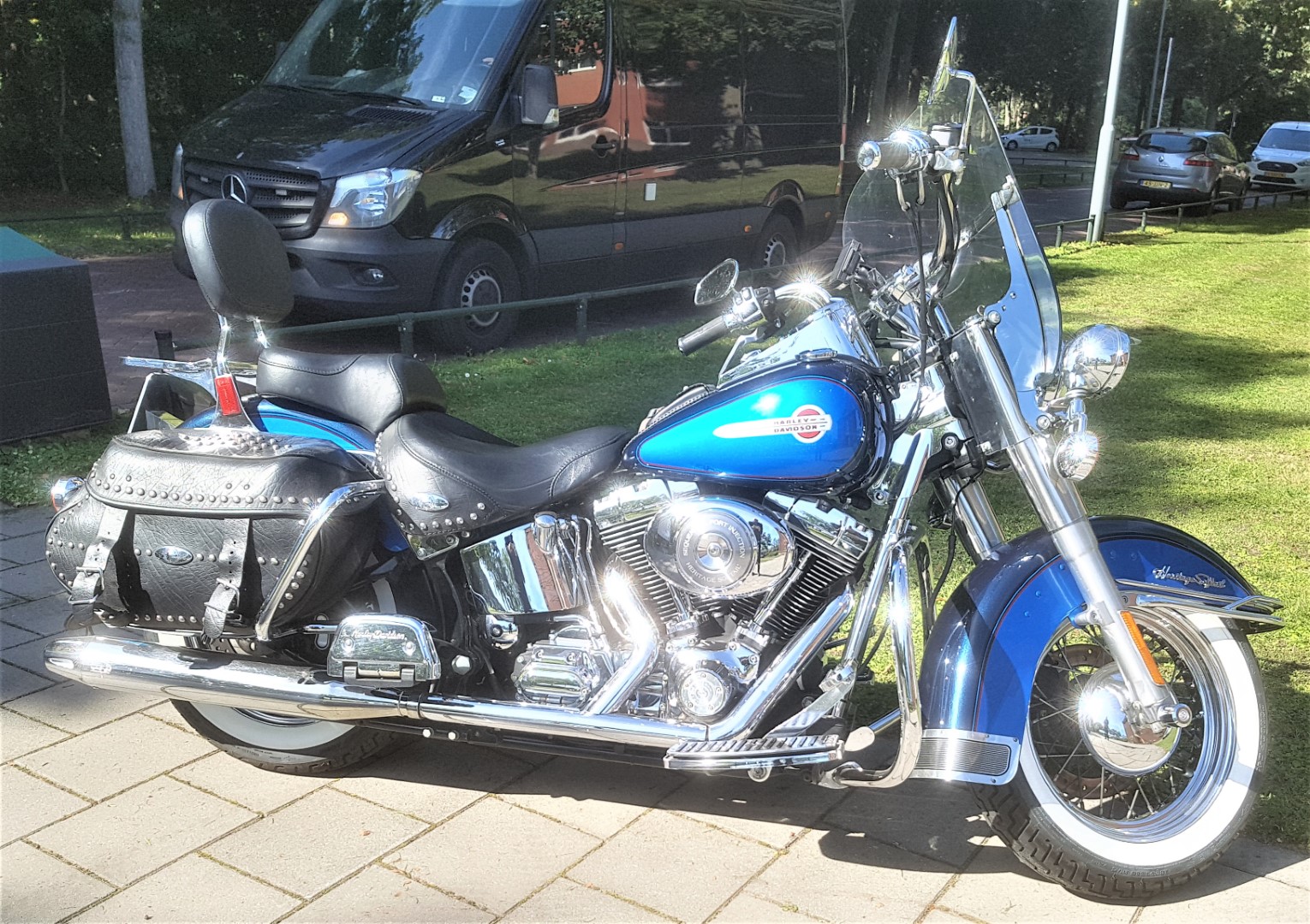
My 2004 fuel-injected HD Heritage is all original, except for the tyres. I decided to get Michelin’s instead of the HD whitewall ones, to get better grip during the rainy days..
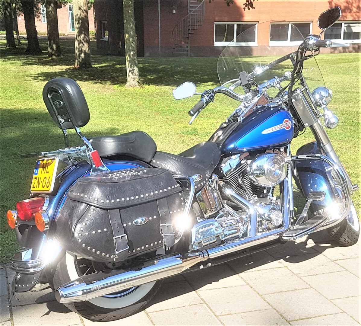
The Heritage as I drive it presently
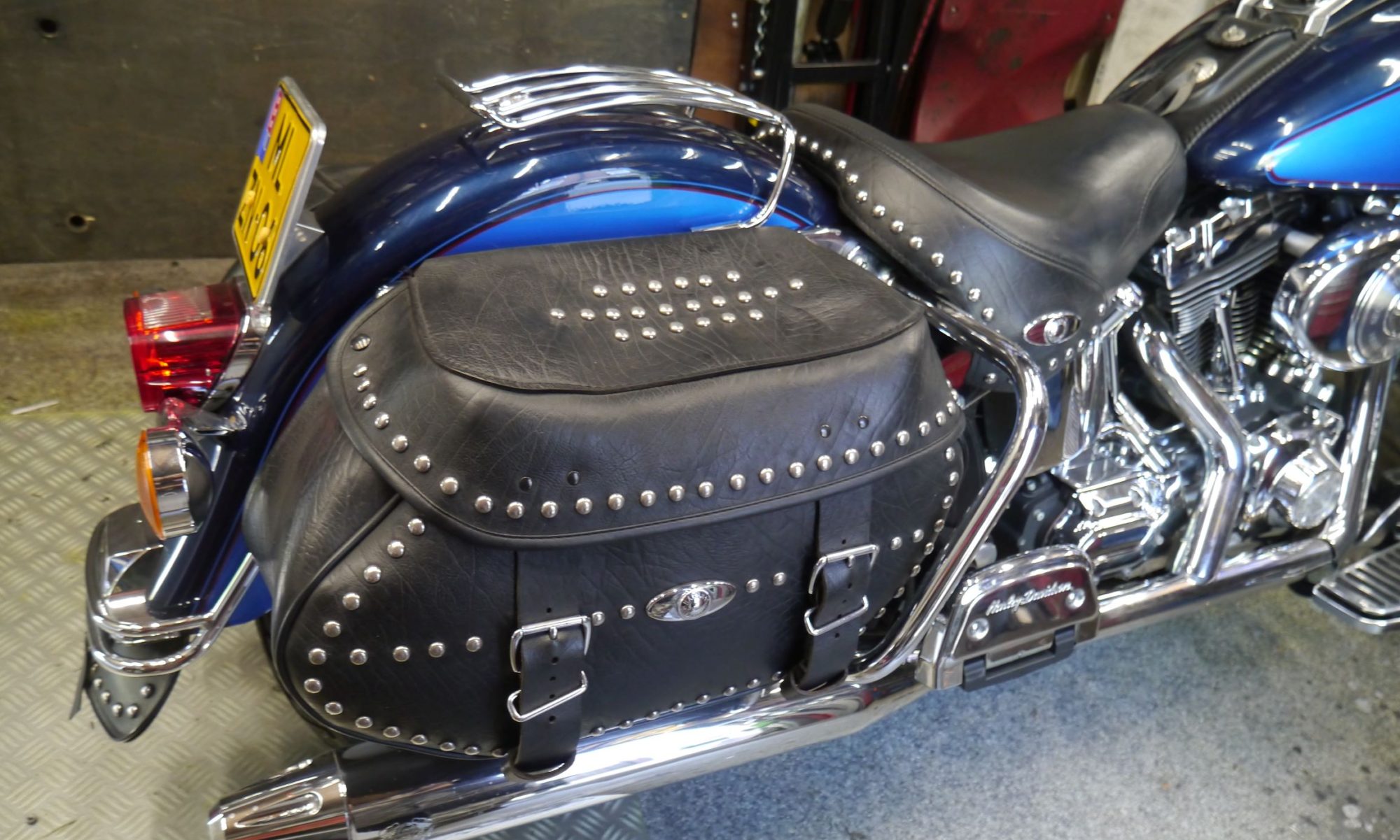
And- Next to the original saddle bags, I added an original Road King top case, also full leather. Top case and saddle bags are easily detachable with original HD detach kits. I added locks to all 3 cases.
The exhausts are also HD, but not as it came from the factory. Due to noise regulations in Europe, I installed extra baffles, full-length in both pipes.
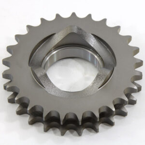
And- the original primary front sprocket has been changed to a bit larger one, so I can drive on the highway with less rev’s.
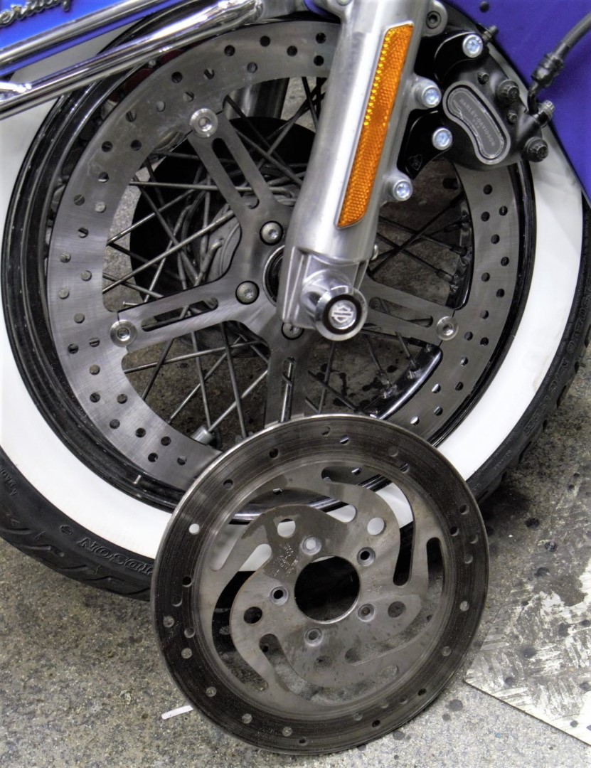
To get better front braking I exchanged the front brake disc for a larger one.
The lights all around are original HD LED.
Original toolbox was also an aftermarket add-on I installed.
I also exchanged the floorboards for a bit less wide ones, due to scraping the originals over the street now and then. We have quite a lot of roundabouts in The Netherlands and the softail design in combination with my drive style caused unexpected contact between the floorboards and the concrete. I did get the softail dampers (this 2004 version has 2 in parallel) at the highest possible position so the rear swing is a lot stiffer and this gave some additional much needed height…
The bike now has 52.000 Km’s on it, and I wil be driving it a bit more the coming years.
This Xmas- star measures 50cm in diameter from left- tip to right-tip. I printed it with glow in the dark ABS, white. It glows in very faint green, it is just enough to glow a little and keeps your eyes focused on the star when it is not lit.
If you make the star legs watertight with silicon sealant, the star can easily be attached to an outside wall, door or fence.
The power supply to the Arduino Nano is 5V DC.
You can use a long 3-wire cable between the Nano and the Xmas star to keep the electronics mounted inside the house and the star outside, or as I did: hang the star inside, in front of any window. I have the star hanging in my front door window, which gives amazing effect due to the non-transparant glass.
Or you can mount the Nano in a small watertight (3d printed) box close to the star and power the nano with 5V.
The programming can be altered to make the light effects behaviour any way you like. I usually have a non-stroboscopic fluent scene running.
You need to print 5 star points, feed the LEDs through them and then have the wires come out somewhere. You can glue the points together with hotglue or transparent silicone sealant after assembly and testing.
Solder the 3 wires of the WS2812 LED string to the Arduino Nano (5V to 5V, Gnd to Gnd and the Data IN of the LED string to D3 of the Arduino Nano. That’s it! After that you can connect the Arduino to your PC with a data USB cable and download the code from my website.
If you don’t have the Arduino IDE yet, download the app from the Microsoft website (Arduino IDE) nor from the Arduino cummunity forum.
Make sure you download my Arduino code and open it with the Arduino IDE APP. Probably the APP will have to move the arduino INO file to a new directory but that should do the trick. If not, start the Arduino app, open my code in notepad and copy/paste it as fully new code into Arduino: Replace the example code that automatically opens when you open the Arduino program/app with my code. Save it and rum it to see wether you need to add any library. For adding libraries, find general help in the Arduino forum. In my code, you can find the names of the required libraries.
In the Arduino IDE select the right microprocessor (Arduino Nano). Then select the correct processor version (large or small memory) and the old or new bootloader. These choices depend on the type of Nano you bought or still had lying around. Then you choose the right port (USB) for your Nano.
To test if you have connection between IDE and Nano , you can ask if the Arduino IDE can read your Nano. Only then you can start loading the Nano with the complicated program.
The BIG 70cm width 5-pointed star with thin hollow legs to put the WS2812 LED string through. AND an integrated tube to put the wiring through
Cheers!
The 3d print file for the BIG star is in my webshop HERE.


 site shows my technically based activities. Cheers!