Recently I bought us a portable dual power cooler from Tropicool, 21 liters content. BUT- as I started it up, the noise was a bit more than I expected.
I already own a larger ‘VRIJBUITER’ 38 liters portable freezer/cooler with a compressor that I silenced last year.
This 40 liter machine had a 50mm (2 inch) fan to cool the condensor and I completely repositioned some movable parts to get a 120mm (4.8 inch) fan in the machine instead. The 120 mm fan is a silent fan and this resulted in an almost silent and better operating freezer/cooler. But- this machine does not run on the car battery, only on A/C 230 Volts.
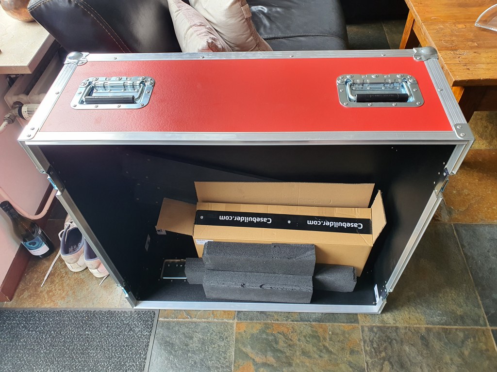
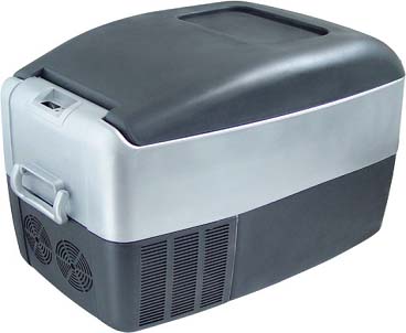
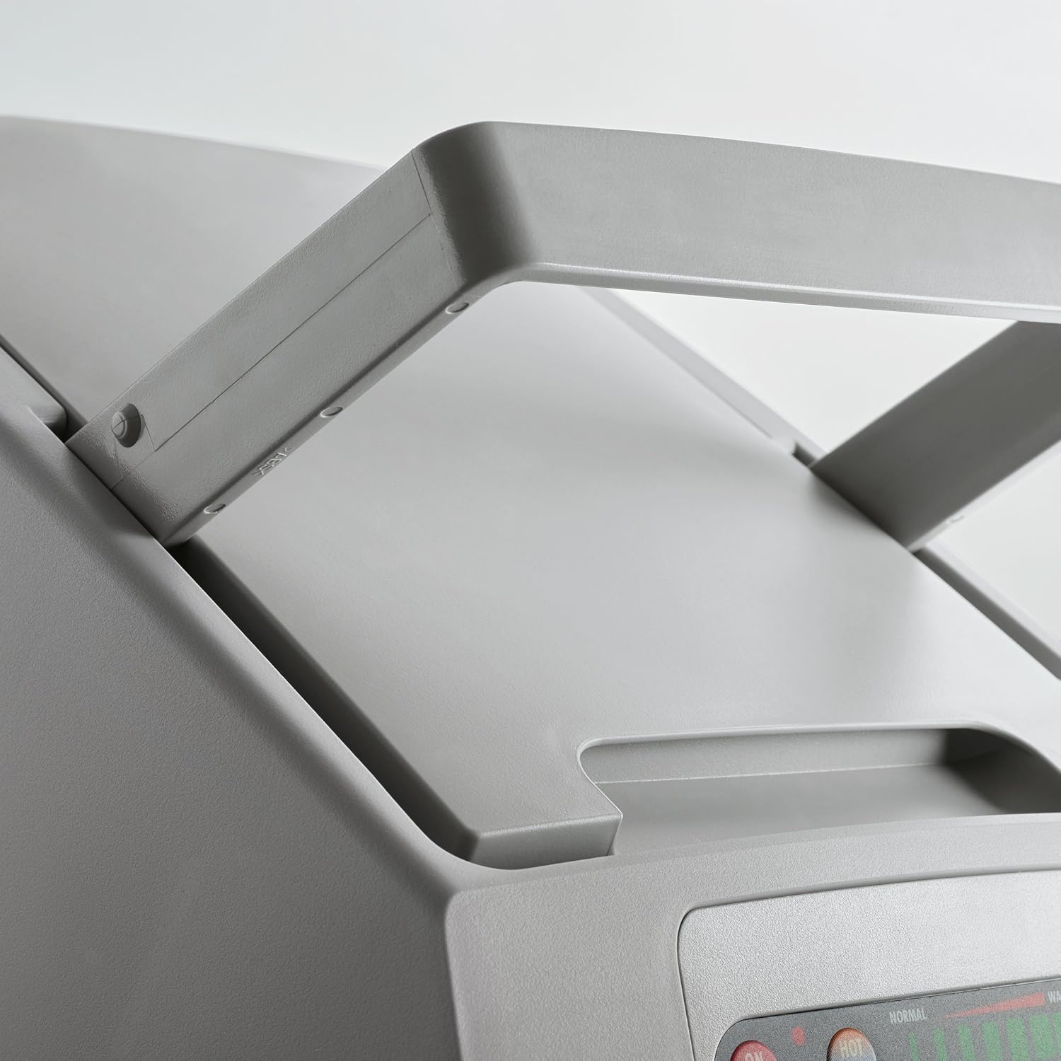
So- back to the Dometic machine: This is the machine
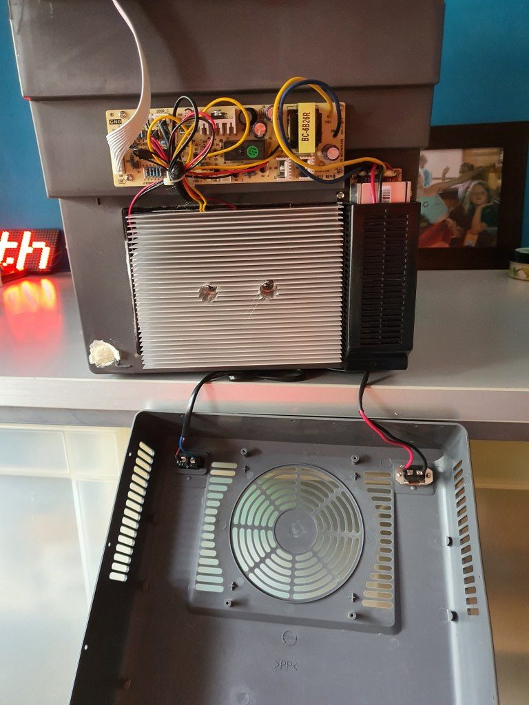
At the front lower part a large area shows a fan behind the plastic front. A 12 Volts DC fan is positioned behind this front . The fan is managed by the electronics and only switches on and off. No PWM or similar technique is used. This cooler is not working with a compressor but with a/some Peltier element(s) and cooling/heating radiators, so a big aluminium block needs to be cooled by the fan to get the machine to work (and cool or warm the inside). This machine can either cool -25Deg C or warm +25Deg C the inside. A failsafe mechanism prevents freezing and temperatures above 65 DegC.
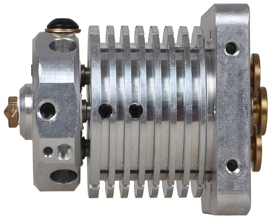
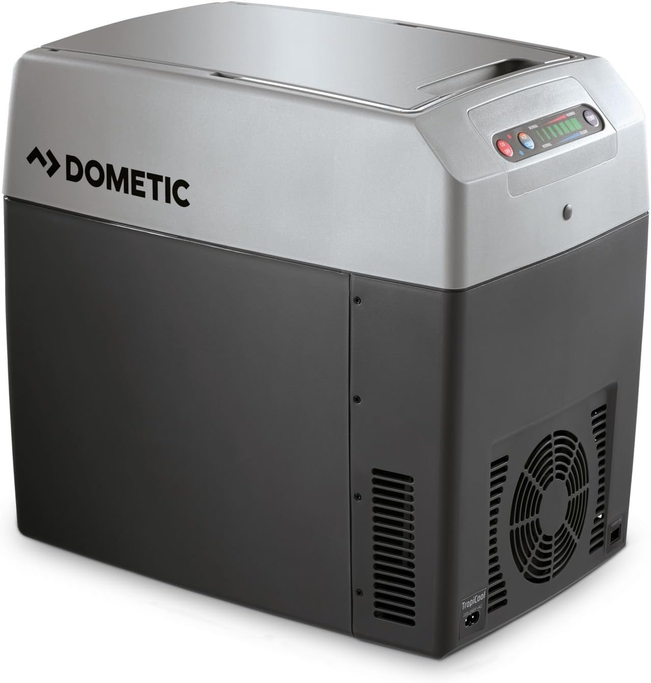
The picture below shows the original fan below and the replacement fan above.
The original fan was IMHO rather loud at 53 dBm (at 50cm distance), I presume mainly due to its design.
On the net, I read that most users of this machine are pleased with it and don’t think it makes much noise.
But- I need to operate this in our rented place which can either be an apartment, B&B or hotel room during our visits so I want it to make as little noise as possible. The replacement fan is a ball-bearing super-silent PC fan and runs at 12 Volts.
The replacement was quite easy: Open the lower front by removing all crews around and bottom. Disconnect the fan-connector from the electronics board. Unscrew the old fan. Screw the new fan in place. Connect the new fan to the electronics board, replace the housing part and screw it back in place.
So- the result is that this cooler now actually works a lot more silent, AND a lot better.
I could not get a fixed dBm reading with my portable dB-meter due to the low noise level.
Cooling goes faster than before at about 30% as I measured it in difference in the before- and after situation in cooling to 5 degrees C from room temp of 25 deg C. Another succesfull project!
We’ll see how we like this cooler during our short stay in France this summer, in Granville! C) JG 2021-06-30.
Afterthoughts: To be sure that the cooler is indeed super silent at night, I also put in a DC voltage regulator that can regulate the voltage for the fan between 5 V DC and V max (about 12Volt).
During oiur holiday in France, the machine worked awesome.
In the hotel, we experienced no disturbances from the cooler at all, nore in the car.
And it kept everyrhing cool without too much noise.


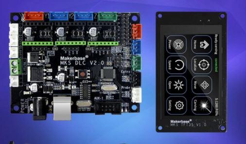
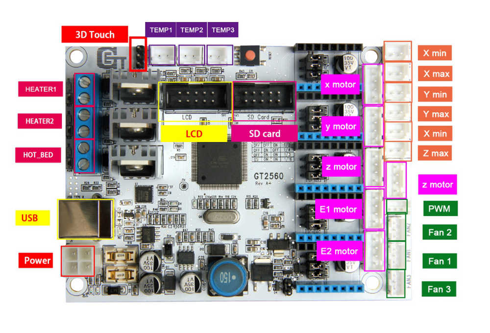 The main reason to NOT use this is the fact that the GT2560 board just has not got enough pins available onboard for things like a handwheel and other outputs for accessories. The second thing that prevents me from going this way is the fact that it proved impossible to have a functional LCD attached that shows things like position, speed, status et cetera.
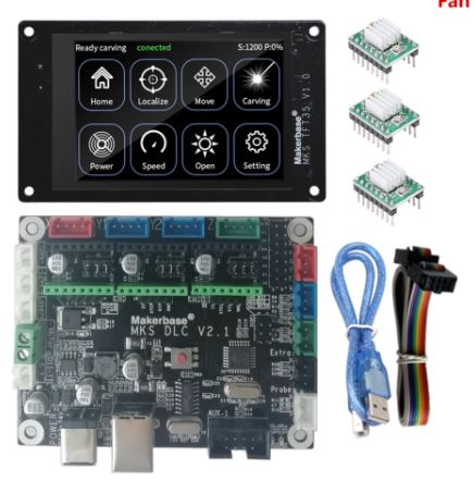 Also for this setup: No option for squaring the dual Y axis setup. But- this is a very neat solution for smaller machines. or larger, if you use external drivers. The nice option of this setup is the 3.5 inch LCD that also comes preconfigured for CNC. I use this for my small 3018 CNC.