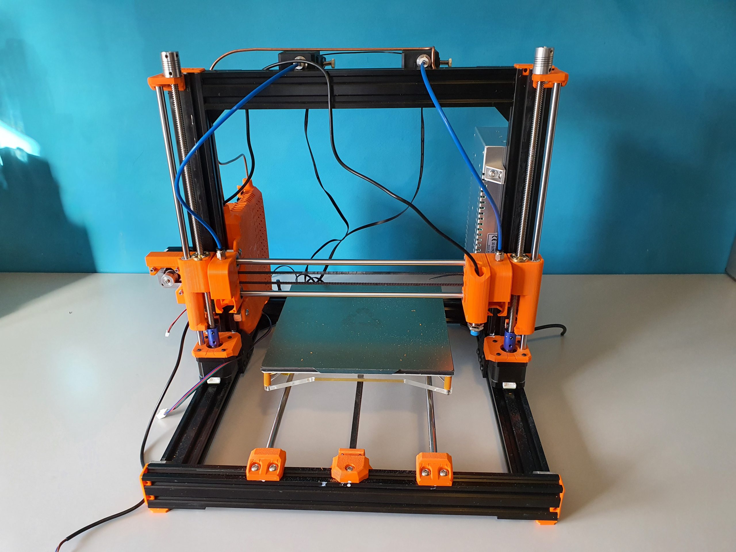
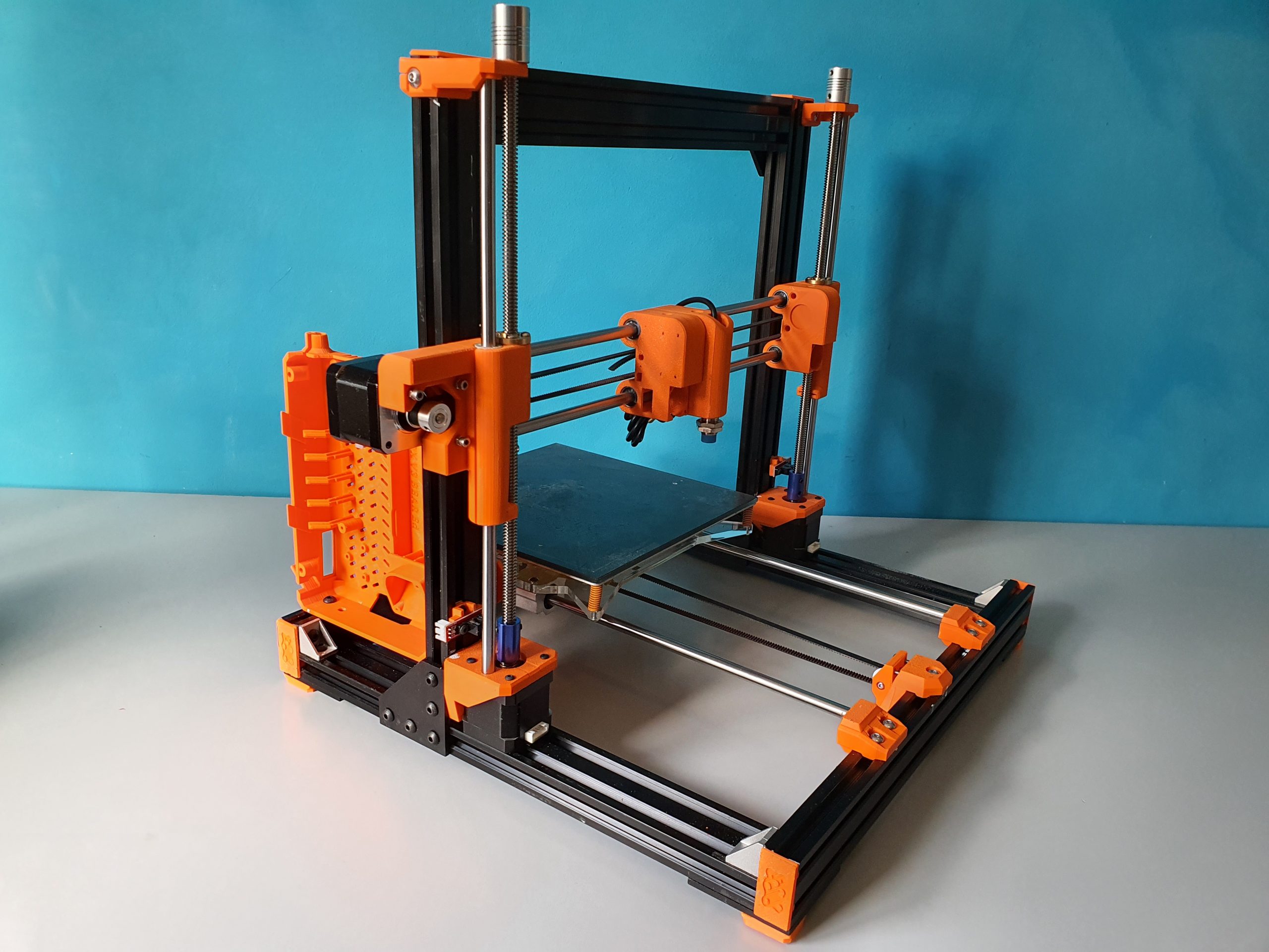
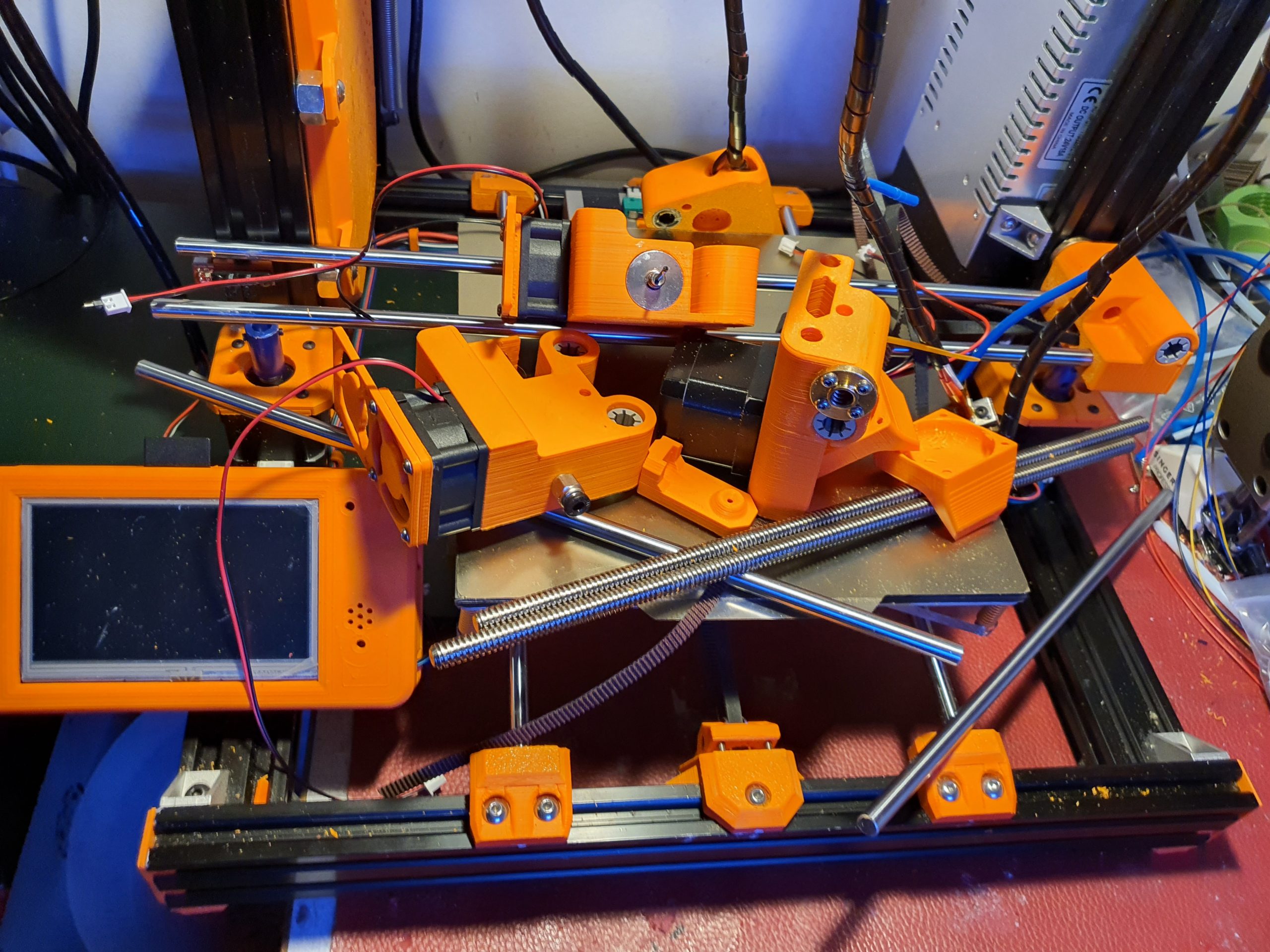
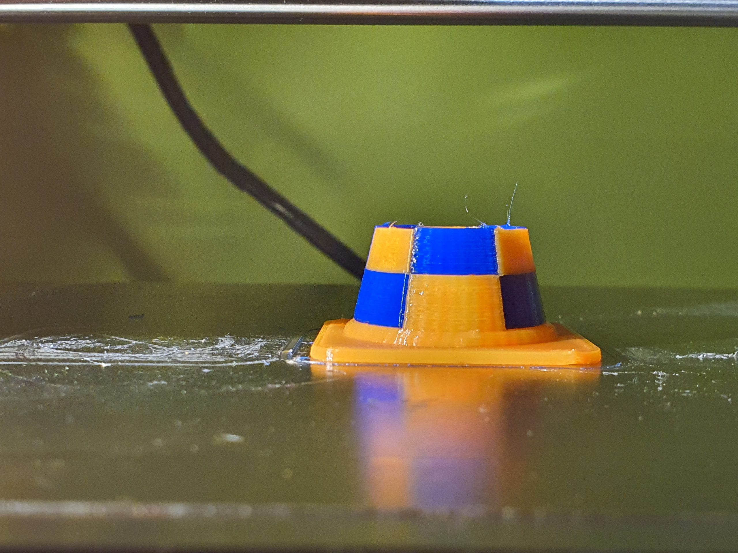
K40 lasercutter

My Chinese lasercutter which I bought back in 2014 has been upgraded over the years.  As many others do, I got the cooling system for the laser tube inside the casing, added some LED lights inside and also added an air pump for the laser head.

All in all the machine works fine now but the relatively small working area remains the bottleneck for using this machine for real interesting projects.

Mid-2020 I used the laser cutter for a couple of projects where I needed series of cut acrylic.  The machine handled this flawlessly, but I did put it outside to prevent any smoke from entering our home.

I do have some ideas about upgrading the machine with a larger workspace and put the electronics and water cooling system in a seperate housing.  No materials are needed for this, except 3 linear rails and some aluminium profiles.  But- (status May-2021)  I will start this project only if there is some work to be done with the machine since it is already working fine as it is, although the workspace is limited.

I use Inkscape (freeware) for making designs in SVG and import these .SVG files in K40whisperer (also freeware) which then  can send the required Gcode to the K40 lasercutter. This all works very well and fast, you don’t need a fast computer for this.  I use a 10 year old dedicated HP laptop for this.

In future use I want to make this lasercutter use the same board as I am using with my big LED laser cutter, so I can use GRBL on both.

As you probably know, a K40 or any other CO2 lasercutter can cut a specific kind of materials while a common LED lasercutter can cut other kind of materials better, due to the used kind of light on both which differ in wavelenghts.

The CO2 cutter can cut acrylic easily and the LED laser cutter can’t.

The LED cutter requires some sort of substance in the to be cut material to work properly.

Be aware that the security goggles you need also are specific for either macine.

The original driver board of the K40 CO2 lasercutter
First cut on a piece of tripledeck 4mm multiplex for my clock pieces
The clock’s interior and stand pieces, wood and acrylic. Both cut on the K40
The inside of the K40’s work space with the debree on the bottom. The air hose is green silicon. Also added an emergency cutoff switch for the laser tube. open the hood and the power stops.
The electronics and water cooling on the Right hand side of the K40’s housing. The air cooled radiators are just out of sight to the most right hand side of the housing, 3 pieces of 40x40mm
The acrylic cut for the clock, done in 1 time. This is 3 mm thick.
The thermostatic control of the coolant pump, taken out of its case to set the working temperatures
My solution for the cutting bed was to use an old footboard maze and I welded 4 nuts in it with long bolts that act as feet. This makes it possible to adjust the height 1x for optimum focussing the laser in the center of the to be cut material.

Circular clock WS2812 & Arduino nano

LEES DIT ARTIKEL IN HET NEDERLANDS

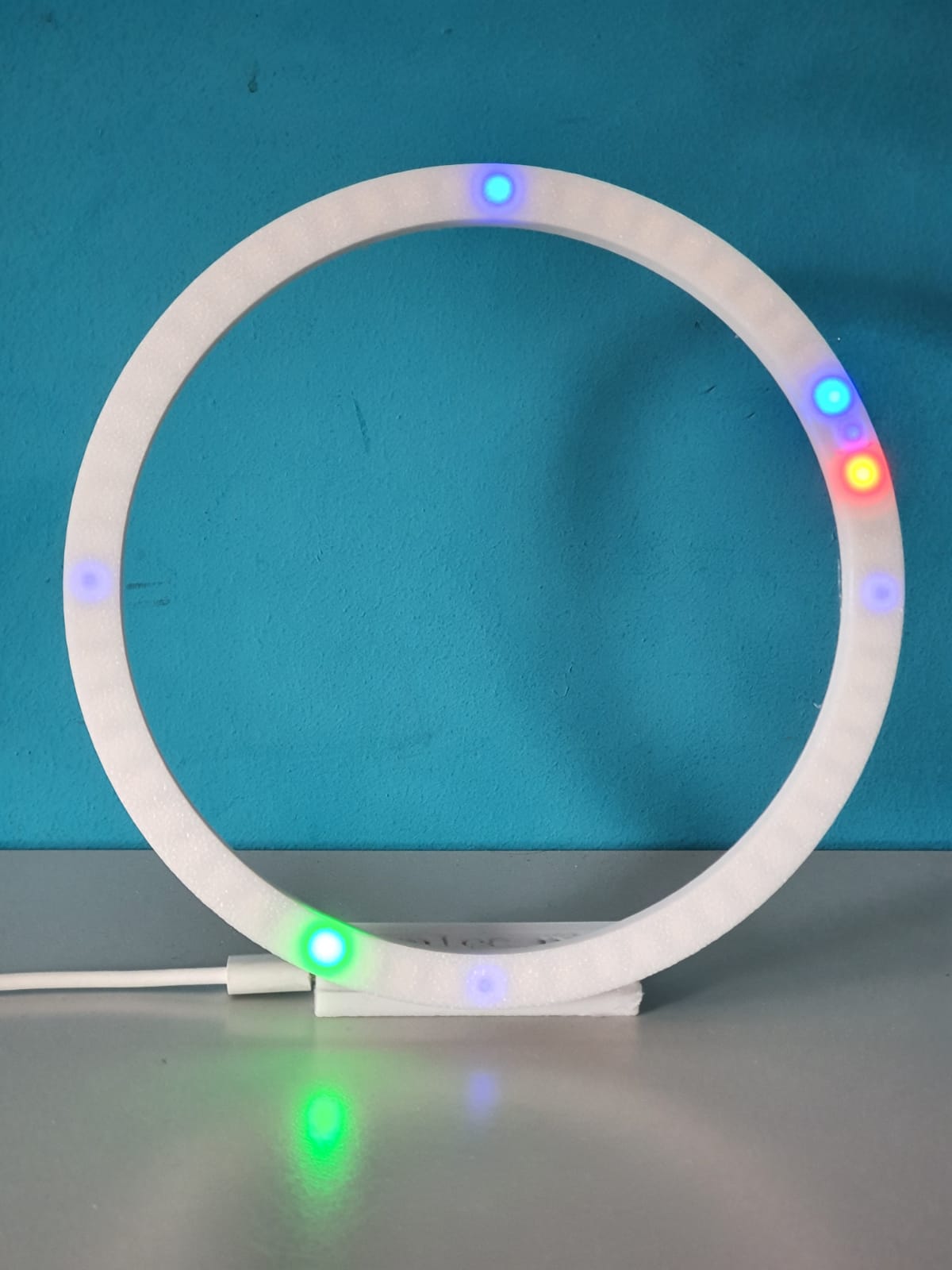
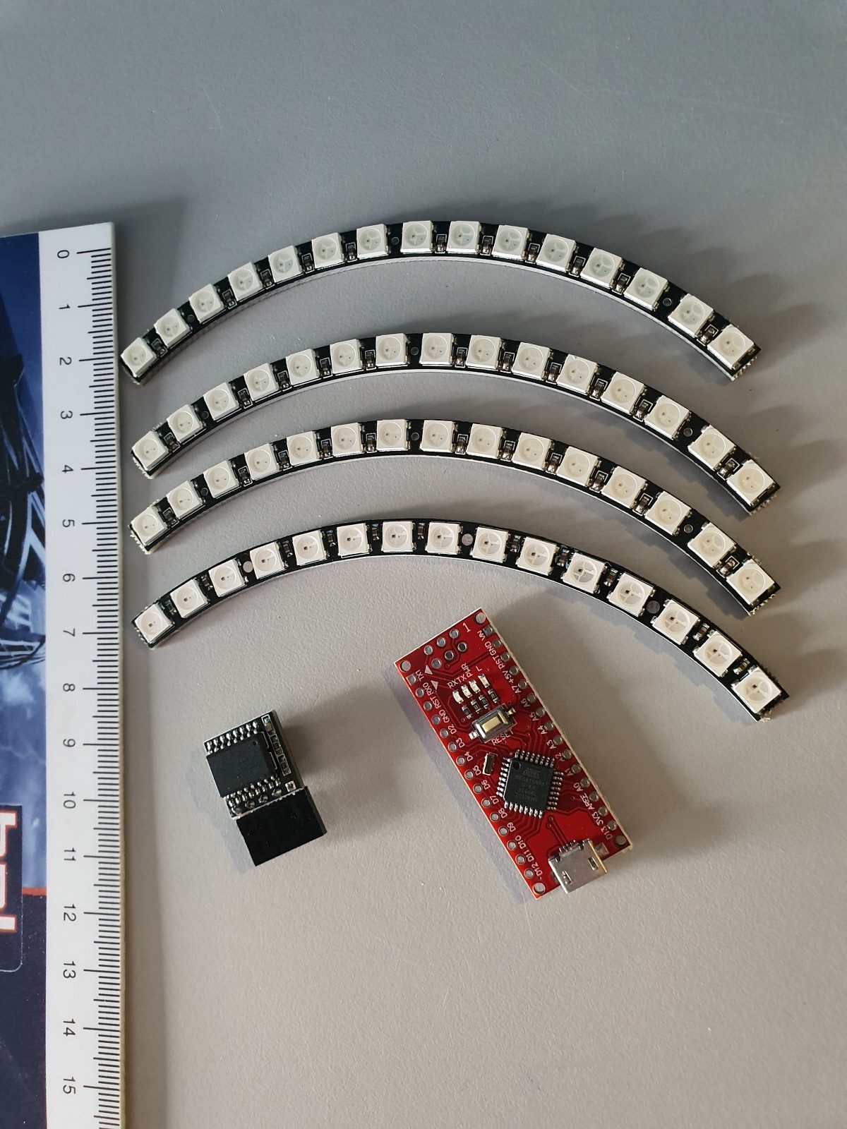
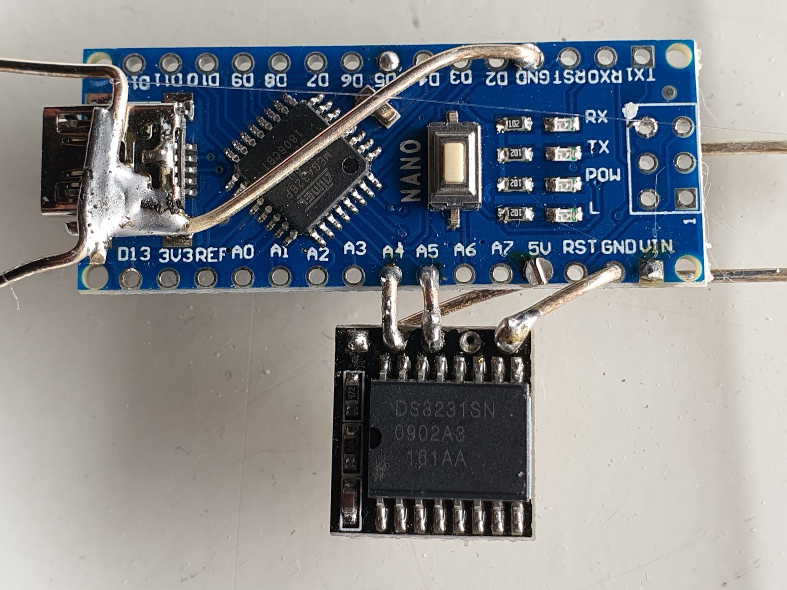
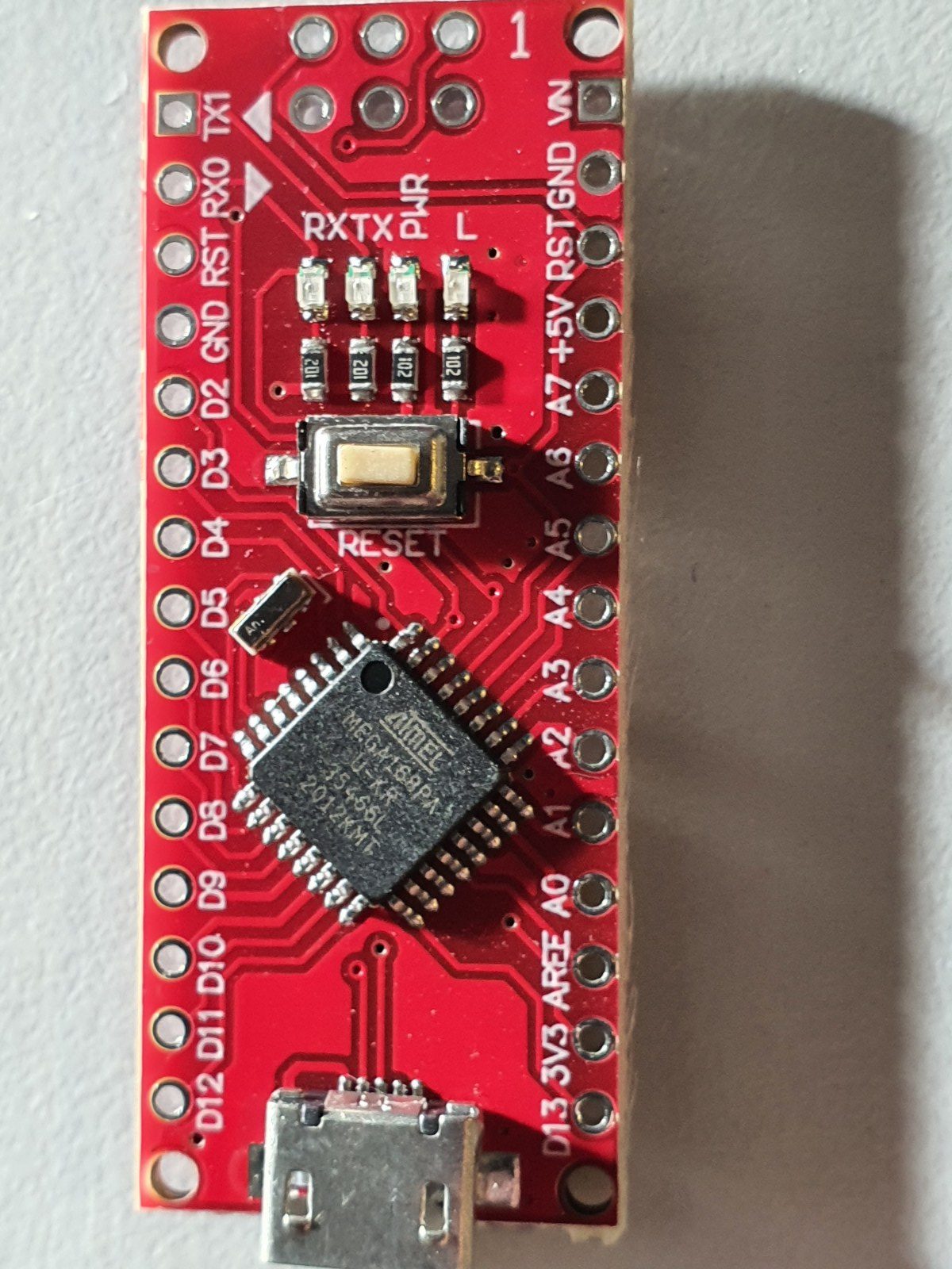
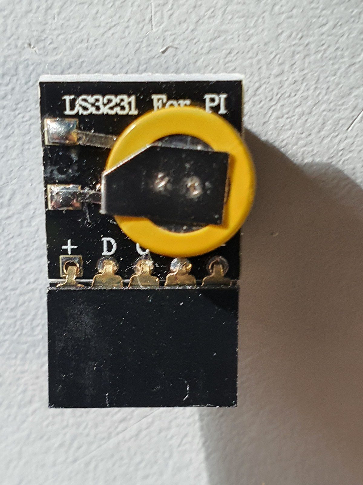
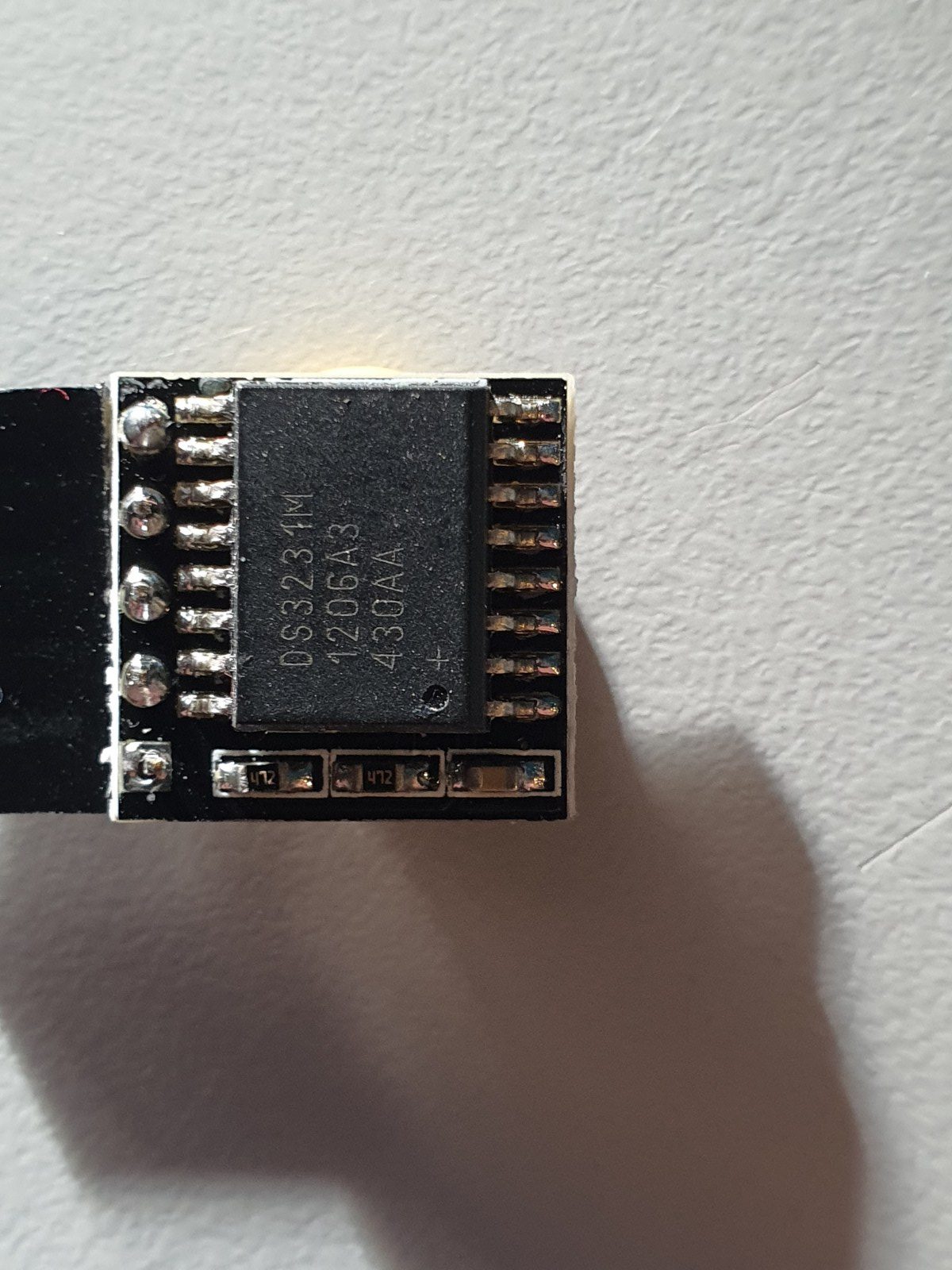
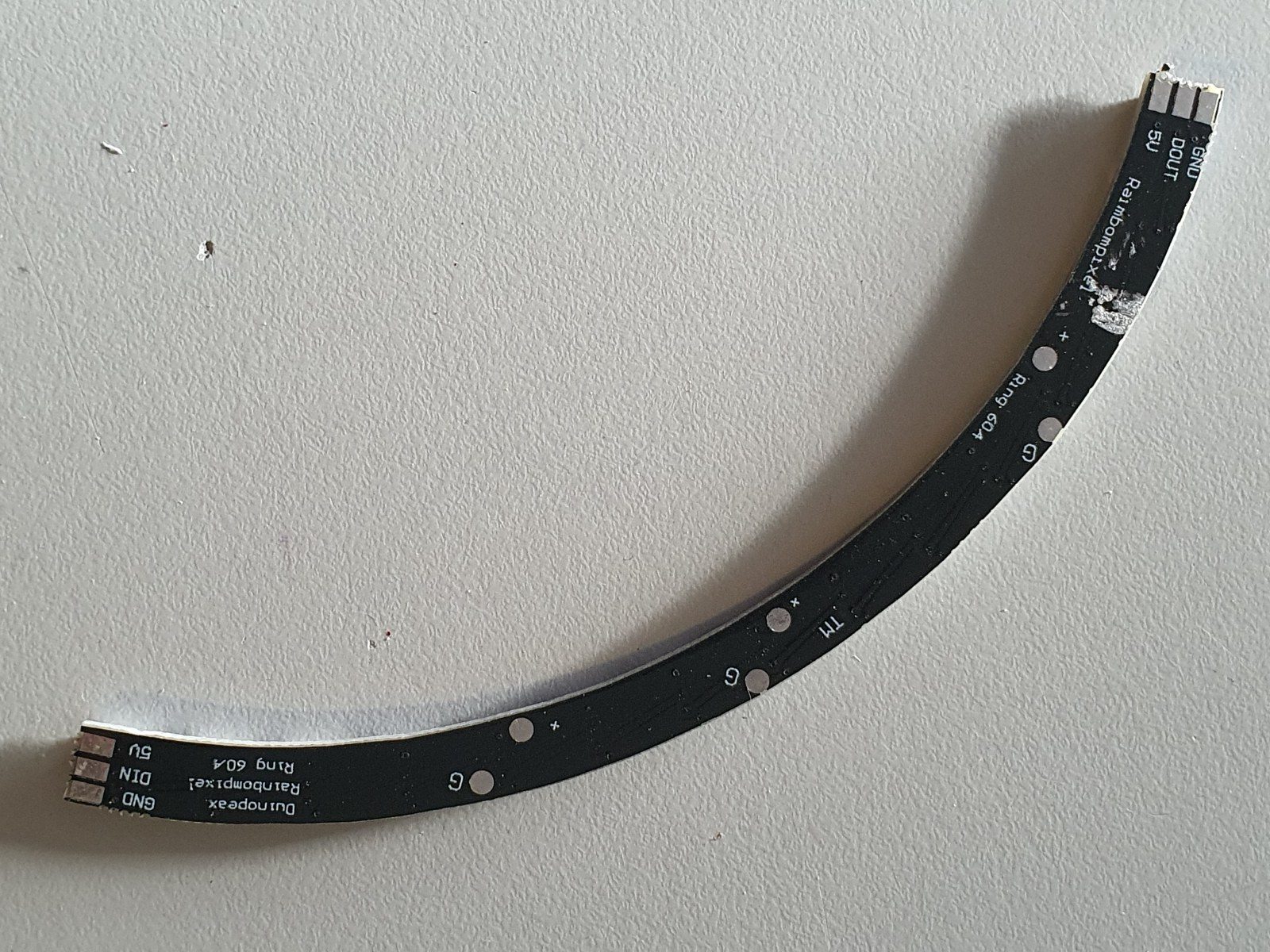
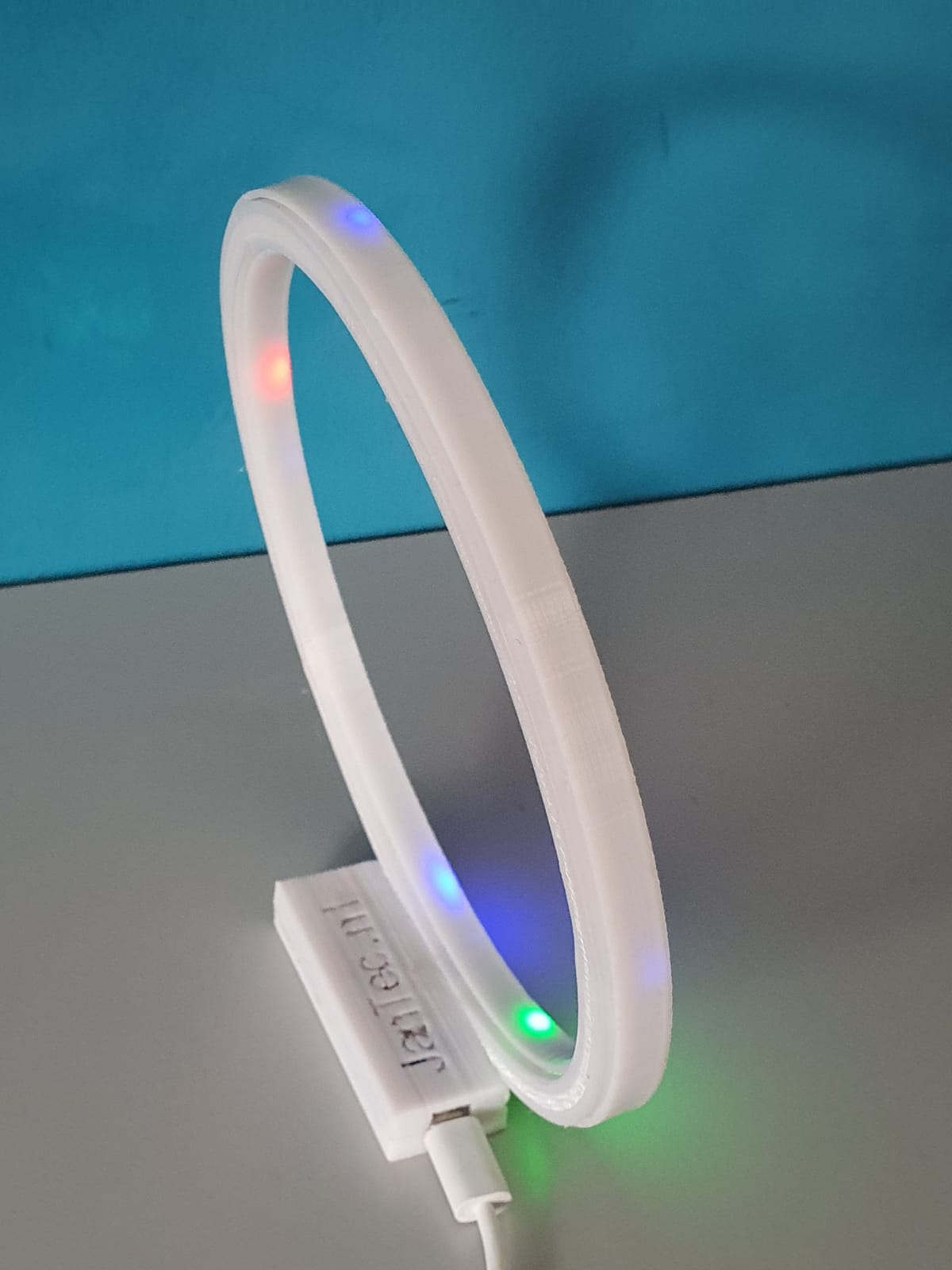
In the above video you see all required parts for the elctronics.  An arduino Nano, a time module LS3231 with battery back-up and a 4-parts ring each with 15 WS2812 LED’s that provide a 160mm 60 LED units clock.  You can build it as an open built unit as shown above with wire strings or in a 3d printable slim case that I developed.  See the pictures below.

For building this nice precise clock, you can use my design files for the housing on any 3d printer that has a horizontal bed size of at least 165x165mm.

Grab both the print STL’s . HERE. from the Prusa shared site where I uploaded these designs. (If the link breaks, search on the prusa site for ws2812 circular arduino clock).

OR get the STL file for the clock’s FRONT from my website HERE

AND get the STL file for the clock’s REAR from my website HERE

One STL is for the rear and includes the Nano box, the other is for the front face of the clock.  Position the rear STL 180 degrees (so up goes down) in your slicer, so both the box and the LED housing are at Z-0 level, i.e. facing down at the same horizontal level.   The front can best be printed with the flat side down.  ABS is not recommended since it has less stiffness, but will probably also work.  For me PETG or PLA works best.

Use white filament for the front part, the rear can be any color you like.

In the circle the 4 WS2812 LED segments are positioned in 1 full circle of about 160mm.

Once you have the rear electronics connected, the front will slide snug over it. No glue required.  But the LED ring can best be glued in 4 places with a drop of hotglue to the base of the rear housing.  Best to do this after you are sure everything works OK.

The LED parts are available on a.o. banggood , aliexpress and so on, search for 60LED circle WS2812 that has the 160 mm outer diameter.

Each LED represents a dot either for seconds, minutes or as hour indicator.

The colors detemine the function.  Blue is also used as Quarter indicator with less intensity, to have a feeling of positioning for the other LEDS when it is dark.

Please look at the video above of the ‘open’ demo model to understand how it works.

Below you can find the Arduino code for the used Nano3, as-is.  it works for me, and in the code you will also find all required electrical connections and the used Time module’s spec.

When connected to your PC, you can program the Arduino and via the serial interface you can afterwards change special settings of the clock like brightness, special quarter dimlit indicators, et cetera.  it’s all in the code below.

The controls can be sent via a serial interface with the usb input of the Arduino, via a terminalprogram like YAT or with the Arduino IDE program’s interface.

The commands are:

  • f; fader OFF
  • F; fader ON
  • m (number); dim the 4 blue marker LED’s with value (number)
  • S; sync to RTC time
  • s; sync to System time (computer)
  • t (time); change system time to:
  • b; brightness of all non-marker LEDs

Please donate $1 to my paypal account if you use (parts of) my developed materials so I can continue to share nice stuff for you to download

Hope you will have a good build!

Cheers,

jan
The Arduino code, to be used for programming the Arduino Nano3 is available at the bottom of this post as plain text to be imported in an empty arduino file (with copy and paste).

Take care to use only the libraries and time module that are specified in the code!  The used time module is of the better generation that holds the time very well, also on standby.

When connecting the wires between the neopixel segments, the arduino and the time module, use a temperature-regulated soldering tool.  Use a fan when you are soldering and don’t inhale the toxic gases while soldering.
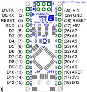
The Arduino code is shown below, to be imported in Arduino in an .ino file.  With Arduino, you must compile the code to get the Arduino flashed with the program.  If you want to do this easier, you can make use of the binary file I already compiled for both Arduino nano versions (with full memory and with half memory). Both Arduino nano types will be OK to use for this build, but they each require specific firmware.

The last part of this post is the Arduino program for the clock:


/**
* NeoClock
*
* Clock using 60 WS2812B/Neopixel LEDs and DS3231 RTC
* Small changes and updates made by jan Griffioen, Amsterdam Europe 2018-2021
* Libraries needed:
* * Adafruit NeoPixel (Library Manager) – Phil Burgess / Paint Your Dragon for Adafruit Industries – LGPL3
* *
* * Arduino Timezone Library (https://github.com/JChristensen/Timezone) – Jack Christensen – CC-BY-SA
* * Time Library (https://github.com/PaulStoffregen/Time) – Paul Stoffregen, Michael Margolis – LGPL2.1
*/

#include <Adafruit_NeoPixel.h>
#ifdef __AVR__
#include <avr/power.h>
#endif

#if defined(ESP8266)
#include <pgmspace.h>
#else
#include <avr/pgmspace.h>
#endif

/* for software wire use below
#include <SoftwareWire.h> // must be included here so that Arduino library object file references work
#include <RtcDS3231.h>

SoftwareWire myWire(SDA, SCL);
RtcDS3231<SoftwareWire> Rtc(myWire);
for software wire use above */

/* for normal hardware wire use below */
#include <Wire.h> // must be included here so that Arduino library object file references work
#include <RtcDS3231.h>
RtcDS3231<TwoWire> Rtc(Wire);
/* for normal hardware wire use above */

#include <TimeLib.h> //http://www.arduino.cc/playground/Code/Time
#include <Timezone.h> //https://github.com/JChristensen/Timezone

#include <EEPROM.h>

//Central European Time (Frankfurt, Paris)
TimeChangeRule CEST = {“CEST”, Last, Sun, Mar, 2, 120}; //Central European Summer Time
TimeChangeRule CET = {“CET “, Last, Sun, Oct, 3, 60}; //Central European Standard Time
Timezone CE(CEST, CET);

TimeChangeRule *tcr; //pointer to the time change rule, use to get the TZ abbrev
time_t utc;

#define PIN 5

unsigned long lastMillis = millis();
byte dimmer = 0x88;
byte hmark = 0;

byte ohour=0;
byte ominute=0;
byte osecond=0;

boolean fader=true;

Adafruit_NeoPixel strip = Adafruit_NeoPixel(60, PIN, NEO_GRB + NEO_KHZ800);

void setup() {

Serial.begin(57600);

strip.begin();
strip.setBrightness(50);

// Some example procedures showing how to display to the pixels:
// colorWipe(strip.Color(255, 0, 0), 50); // Red
//colorWipe(strip.Color(0, 255, 0), 50); // Green
//colorWipe(strip.Color(0, 0, 255), 50); // Blue
//colorWipe(strip.Color(0, 0, 0, 255), 50); // White RGBW
// Send a theater pixel chase in…
//theaterChase(strip.Color(127, 127, 127), 50); // White
theaterChase(strip.Color(127, 0, 0), 50); // Red
//theaterChase(strip.Color(0, 0, 127), 50); // Blue

//rainbow(20);
rainbowCycle(2);
//theaterChaseRainbow(50);

strip.clear();
strip.show(); // Initialize all pixels to ‘off’

Rtc.Begin();

Rtc.Enable32kHzPin(false);
Rtc.SetSquareWavePin(DS3231SquareWavePin_ModeNone);

if (!Rtc.GetIsRunning())
{
Serial.println(“Rtc was not actively running, starting now”);
Rtc.SetIsRunning(true);
}

if (!Rtc.IsDateTimeValid())
{
// Common Cuases:
// 1) the battery on the device is low or even missing and the power line was disconnected
Serial.println(“Rtc lost confidence in the DateTime!”);
}

byte eechk = EEPROM.read(0);
if(eechk == 0xAA) { //Assume this is our config and not a fresh chip
dimmer = EEPROM.read(1);
hmark = EEPROM.read(2);
fader = EEPROM.read(3);
}

timeSync();
}

void calcTime(void) {
utc = now();
CE.toLocal(utc, &tcr);
ohour = hour(utc);
ominute = minute(utc);
if(osecond != second(utc)) {
osecond = second(utc);
lastMillis = millis();

if(ominute == 0 && osecond == 0) {
//Every hour
timeSync();
}
}
}

void addPixelColor(byte pixel, byte color, byte brightness) {
color *= 8;
uint32_t acolor = brightness;
acolor <<= color;
uint32_t ocolor = strip.getPixelColor(pixel);
ocolor |= acolor;
strip.setPixelColor(pixel, ocolor);
}

void drawClock(byte h, byte m, byte s) {
strip.clear();

addPixelColor(m, 1, dimmer);

if(hmark > 0) {
for(byte i = 0; i<12; i++) {
addPixelColor((5*i), 2, hmark);
}
}

h %= 12;
h *= 5;
h += (m/12);
addPixelColor(h, 2, dimmer);
// 0x RR GG BB

if(fader) {
byte dim_s1 = dimmer;
byte dim_s2 = 0;
byte px_s2 = s+1;
if(px_s2 >= 60) px_s2 = 0;
unsigned long curMillis = millis()-lastMillis;
if(curMillis < 250) {
dim_s2 = 0;
dim_s1 = dimmer;
}else{
dim_s2 = map(curMillis, 250, 1000, 0, dimmer);
dim_s1 = dimmer – map(curMillis, 250, 1000, 0, dimmer);
}

// Add blue low intensity dots for 12(0),3, 6 and 9 O’çlock to verify where the clock is positioned..
addPixelColor(15, 128, 10);
addPixelColor(30, 128, 10);
addPixelColor(45, 128, 10);
addPixelColor(0, 128, 40);

addPixelColor(s, 0, dim_s1);
addPixelColor(px_s2, 0, dim_s2);
}else{
addPixelColor(s, 0, dimmer);
}

// add a background color
// setBrightness(Serial.parseInt());
// uint16_t j;
// for(j=0; j<60; j++) { // 1 cycles of colors on wheel
// strip.setPixelColor(j, Wheel(((j * 256 / strip.numPixels()) + j) & 255));
// }

strip.show();
}

byte rounds = 0;

void loop() {
calcTime();

if(rounds++ > 100) {
Serial.print(ohour);
Serial.print(“:”);
Serial.print(ominute);
Serial.print(“:”);
Serial.print(osecond);
Serial.println(“(C)JG-2020”);
rounds = 0;

}
//rainbow(21);
if (osecond == 59){theaterChase(strip.Color(0, 0, 127), 40); }// Blue; }
//if (ominute == 59 AND osecond == 59){theaterChase(strip.Color(0, 127, 0), 50); }// Green}
//if (ohour == 11 AND ominute == 59 AND osecond == 59){theaterChase(strip.Color(127, 127, 0), 50); }// Green}
else {drawClock(ohour,ominute,osecond);}

delay(10);

chkSer();
}

void timeSync(void) {
RtcDateTime dt = Rtc.GetDateTime();
setTime(dt.Hour(),dt.Minute(),dt.Second(),dt.Day(),dt.Month(),dt.Year());

Serial.print(“Synced to: “);
Serial.print(dt.Year());
Serial.print(“-“);
Serial.print(dt.Month());
Serial.print(“-“);
Serial.print(dt.Day());
Serial.print(“-“);
Serial.print(dt.Hour());
Serial.print(“-“);
Serial.print(dt.Minute());
Serial.print(“-“);
Serial.println(dt.Second());
}

void timeSave(void) {
utc = now();

RtcDateTime store = RtcDateTime(year(utc), month(utc), day(utc), hour(utc), minute(utc), second(utc));
Rtc.SetDateTime(store);

Serial.print(“Synced to: “);
Serial.print(year(utc));
Serial.print(“-“);
Serial.print(month(utc));
Serial.print(“-“);
Serial.print(day(utc));
Serial.print(“-“);
Serial.print(hour(utc));
Serial.print(“-“);
Serial.print(minute(utc));
Serial.print(“-“);
Serial.println(second(utc));

}

void setBrightness(byte brightness) {
dimmer = brightness;
}

void chkSer(void) {
unsigned int iy;
byte im,id,iH,iM,iS;

if(!Serial.available()) return;

switch(Serial.read()) {
case ‘b’:
setBrightness(Serial.parseInt());
Serial.print(F(“Brightness changed to: “));
Serial.println(dimmer);
EEPROM.put(0, 0xAA);
EEPROM.put(1, dimmer);
break;
case ‘t’:
iy = Serial.parseInt();
im = Serial.parseInt();
id = Serial.parseInt();
iH = Serial.parseInt();
iM = Serial.parseInt();
iS = Serial.parseInt();
setTime(iH,iM,iS,id,im,iy);
Serial.println(F(“System time changed”));
break;
case ‘f’:
fader = false;
EEPROM.put(0, 0xAA);
EEPROM.put(3, 0);
Serial.println(F(“Fader off”));
break;
case ‘F’:
fader = true;
EEPROM.put(0, 0xAA);
EEPROM.put(3, 1);
Serial.println(F(“Fader on”));
break;
case ‘m’:
hmark = Serial.parseInt();
EEPROM.put(0, 0xAA);
EEPROM.put(2, hmark);
Serial.println(F(“HMark changed”));
break;
case ‘s’:
timeSync();
Serial.println(F(“Synced RTC to System”));
break;
case ‘S’:
timeSave();
Serial.println(F(“Synced System to RTC”));
break;
default:
Serial.println(‘?’);
}
}

// Fill the dots one after the other with a color
void colorWipe(uint32_t c, uint8_t wait) {
for(uint16_t i=0; i<strip.numPixels(); i++) {
strip.setPixelColor(i, c);
strip.show();
delay(wait);
}
}

void rainbow(uint8_t wait) {
uint16_t i, j;

for(j=0; j<256; j++) {
for(i=0; i<strip.numPixels(); i++) {
strip.setPixelColor(i, Wheel((i+j) & 25));//255
}
strip.show();
delay(wait);
}
}

// Slightly different, this makes the rainbow equally distributed throughout
void rainbowCycle(uint8_t wait) {
uint16_t i, j;

for(j=0; j<256*5; j++) { // 5 cycles of all colors on wheel
for(i=0; i< strip.numPixels(); i++) {
strip.setPixelColor(i, Wheel(((i * 256 / strip.numPixels()) + j) & 255));
}
strip.show();
delay(wait);
}
}

//Theatre-style crawling lights.
void theaterChase(uint32_t c, uint8_t wait) {
for (int j=0; j<4; j++) { //do 4 cycles of chasing
for (int q=0; q < 3; q++) {
for (uint16_t i=0; i < strip.numPixels(); i=i+3) {
strip.setPixelColor(i+q, c); //turn every third pixel on
}
strip.show();

delay(wait);

for (uint16_t i=0; i < strip.numPixels(); i=i+3) {
strip.setPixelColor(i+q, 0); //turn every third pixel off
}
}
}
}

//Theatre-style crawling lights with rainbow effect
void theaterChaseRainbow(uint8_t wait) {
for (int j=0; j < 256; j++) { // cycle all 256 colors in the wheel
for (int q=0; q < 3; q++) {
for (uint16_t i=0; i < strip.numPixels(); i=i+3) {
strip.setPixelColor(i+q, Wheel( (i+j) % 255)); //turn every third pixel on
}
strip.show();

delay(wait);

for (uint16_t i=0; i < strip.numPixels(); i=i+3) {
strip.setPixelColor(i+q, 0); //turn every third pixel off
}
}
}
}

// Input a value 0 to 255 to get a color value.
// The colours are a transition r – g – b – back to r.
uint32_t Wheel(byte WheelPos) {
WheelPos = 255 – WheelPos;
if(WheelPos < 85) {
return strip.Color(255 – WheelPos * 3, 0, WheelPos * 3);
}
if(WheelPos < 170) {
WheelPos -= 85;
return strip.Color(0, WheelPos * 3, 255 – WheelPos * 3);
}
WheelPos -= 170;
return strip.Color(WheelPos * 3, 255 – WheelPos * 3, 0);
}

Kingroon KP3

This is my spare machine, wrapped in – to use when any other machine should have an unsolvable problem (at least- short term).  This 1st version Kingroon KP3 mini always works flawlessly on PLA and PETG. I did add some after market stuff like better cooling, new firmware et cetera.  If I use this machine, I always manage it remotely with an Octopi on RPI.

Replaced the waterpump of my Citroën ID20 cabrio (1970)

July 2019: I noticed a small amount of coolant under the car from time to time, after parking.

So looking for the cause, and as a precaution, I immediately replaced the water pump housing, thermostat, lower hoses and water pump.

Also replaced all gaskets, cleaned the surfaces, checked all hoses optically and so on.

After fitting, first tested the cooling system with a pressure kit and left it pressurized overnight.  No leakage.  The action seems to have been successful.

Update 3-2021: After this action, it appears that there is still a little coolant under the car when I have driven a bit after which the car has been parked overnight.  While driving, the car does not seem to lose anything.

It seems that as the car cools down, it builds up so much pressure in the cooling system that there is leakage that does not occur while driving. Possibly the expansion and contraction of the engine parts has something to do with this and the contraction after driving could possible cause the extra pressure. Apparently the radiator cap is not the solution to this problem. This cap should open at a certain pressure and allow some of the compressed air at the top of the radiator to escape.  That this principle does work is clear because the catcher at the bottom of the overpressure hose which is mounted at the radiator cap does catch coolant when I have incidentally overfilled the radiator slightly.

In the meantime, I have ordered an overpressure vessel to mount in the cooling circuit to better compensate for the pressure, and a mechanical pressure regulator and valve to adjust this cooling system to a pleasant maximum pressure.  I hope this will stop the cooling system from leaking.

[Best_Wordpress_Gallery id=”57″ gal_title=”Waterpump and -housing renewed ID/DS”]

3d applications – self-folding materials

3D printing became a hot item around 2016,  and quite a few 3d printing machines have been sold over the years.  But, at some point it seems that the use for products from these machines has faded away.

Due to the availability of 3D printers and the fact that these printers are getting better and are producing prints with better quality as they evolve over time, more applications have been developed.

In this article I will sum up a couple of these new areas in which 3D printing became a driver for new developments, which are sometimes just scratching the surface of possible future developments.

  1. Dental products.  For over 40 years , dentists are using Services from laboratories to produce Ceramic protheses for teeth.  The base for this is a mould, taken from the patient.  I recall that this was indeed not a very pleasant process for the patient.  This process was time consuming and it required also some adjusting and fine-tuning at delivering the protheses at the right place.   Currently all dentists are either producing the protheses themselves or use online deliveries that are mostly available with a production- and delivery time of less than 4 hours.  the process starts with a 3d-scan from the patient’s mouth, compared with (if available) older pictures and/or X-rays.  All is fed into a normal PC, and the software makes the 3d print data.  After that, printing the protheses is quite simple with the new ceramic printable filaments. Placing the protheses with UV-herdening glue means that someday we will be able to do this at home. Although the prepping of the place to put the protheses will still be done by a dentist, I presume.
  2. Technical parts.  For many tehnological industries the availability of 3D printers has made it possible to have faster development processes of new parts and applications,  You can think of modeling new tools,  household objects, cars and -parts, and so on.  Since new materials can be printed like aluminium, copper, gold, silver and carbon much is possible. After the developments has produced a complete product, mass-production can start and for this, the 3D design files can be handed over to make the work easy.nn In this way both time and money is saved.
  3. Art.  Maybe not the most obvious development yet, but lately I ran into some artists whom actually used 3D printing in most expressive ways, as art may do.  If you check the internet for this, some interstingexamples can be found.
  4. Medical developments.  Since 2017, a new development achieved the ability for 3D printed parts to shrink and expand, based on the printed structure.  Read this article about self-folding materials
  5. Fun printing. Many hobbyists are printing 3D objects just for fun.  To add-on applications to their 3D printer, build new ones or print household applications.


VORON 2.4 20″x20″x20″ and DUET2WIFI

Get the documentation, specs, config.g, macros and build docs

LEES IN HET NEDERLANDS

After my succesfull buildproject of a Voron 2.4 3d printer in the fall of 2020, I still wanted a really big 3d printer with a print surface of over 20x20x20 inch.

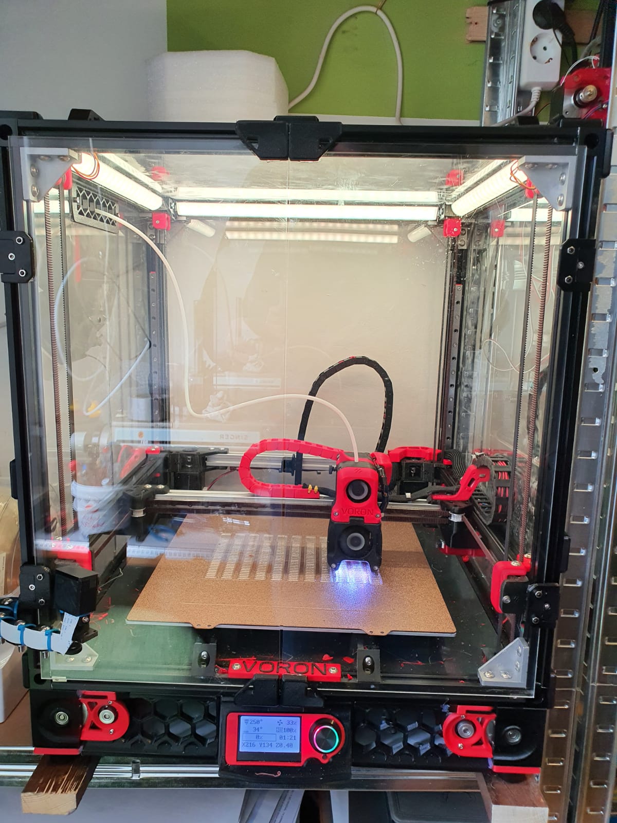
My Voron 300x300x300mm build plate size

Imagine to have a print of more than double the size compared to the below picture!

During the build and at using the Voron 2.4 printer, I found the documentation on the hardware build really excellent.  But, the electronics part was scattered around several places, and although the Klipper implementation is very good I have experienced that the combination of 2 SKR 1.4 turbo motherboards with an Octopi controller does not provide enough operational stability to me. And- I feel the need to control more settings than I can do with the Klipper solution.  I think I probably am just more into the Duet and the reprap solution than the Klipper one, due to previous positive Duet – and MKS reprap experiences.

In a couple of previous builds I used a Duet2wifi, and I also experienced the add-ons for Duet2 like driver boards, PT100 boards and more hardware that is also very well implemented in the new RRF3+ firmware.

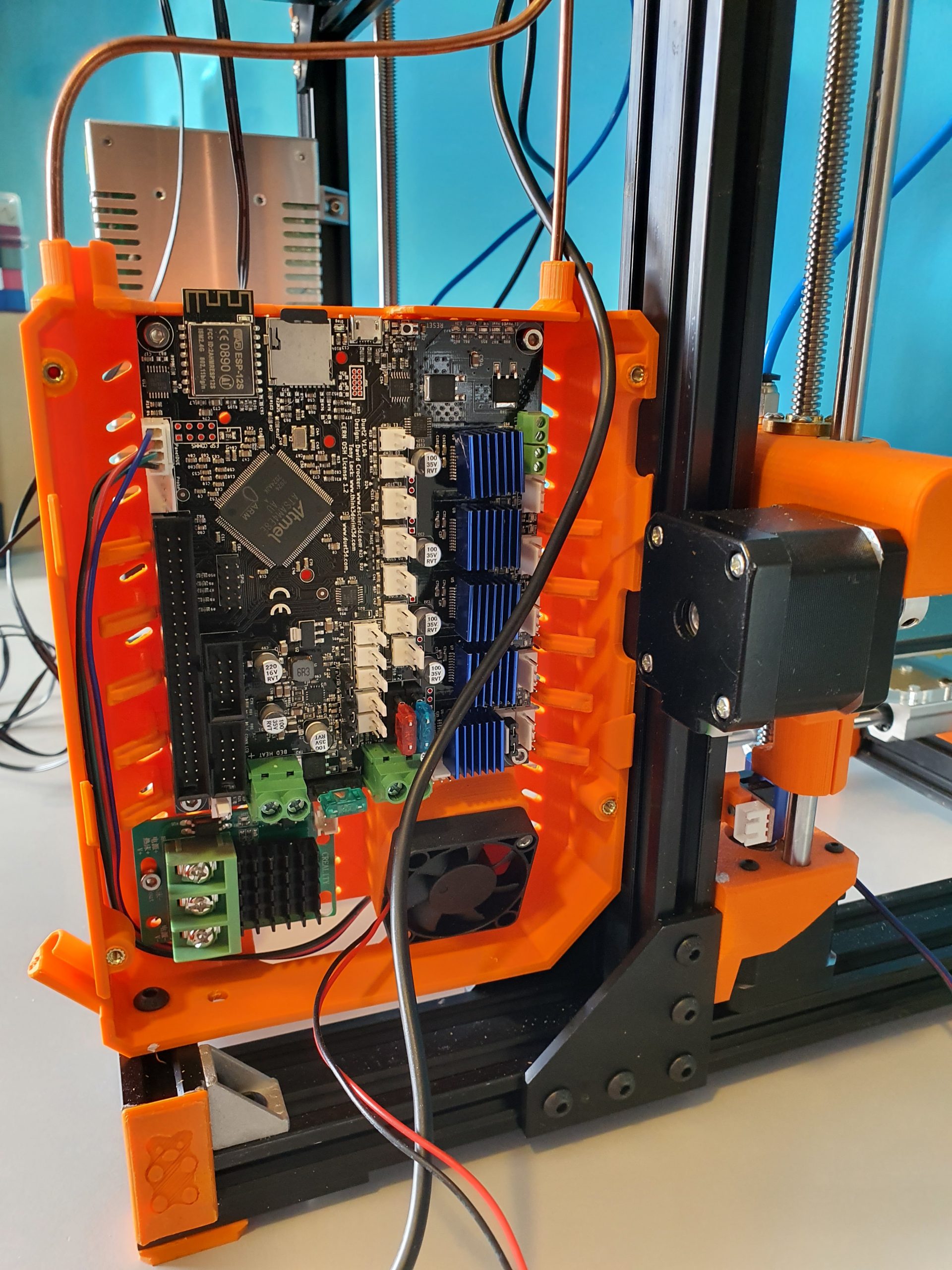
Duet wifi board , used for my dual head setup I3bear-based with sensorless homing

Reasons enough for me to choose the Duet2 and the 5-ports expansion board , or possibly an additional Duex board for my new to build Voron 2.4 ‘big 3d printer’.

At this page, I will share my progess on this build.

I have all required hardware laying around and since I already built a Voron 2.4, I will first focus on the electronics.  For the hardware, I still need the plexiglass sides, top and front doors.  I  do have all extrusion, bed, bed heater 230V, linear rails, all printed parts and so on, neatly stored at home.

So, I am setting up the electronics to know beforehand that everything works well.  I don’t want to start building the hardware and find out afterwards that my Duet2wifi will not do the job I want it to do.

Yesterday (October 4th,2020) I put the electronics and config.g together. I used:

  • Duet2wifi board with 24V PSU and 4.3 inch TFT/LCD
  • 5-port expansion board with 4 plug-in 2209 drivers V3.0
  • Z-switch mechanical
  • X-and Y end switches (hall-effect)
  • Hotend 24V with NTC connected including tool’s fan (I am missing the PT100’s interface board, have ordered one but I did this before so should be no problemo)
  • Hotbed simulated with another hotend including NTC
  • Stepper motors connected to X(0),Y(1) and 1 x  stepper on the expansion board Z(5) (Driver5)

The Duet2wifi board is a Chinese MKS clone with electronics version 1.02 which works fine.  The expansion board is also a Chinese one, but this is a bare-bone  implementation of the 5-ports driver add-on board that comes without drivers.  the nice thing about this add-on board is that drivers can be plugged in directly.

The Duet2 came with firmware 2.1 installed.  To get to FFR3.1, you must first install 3.0 and after this, you can move to 3.1…  be aware!

After updating the paneldue and the Duet2wifi board, I activated the wifi and put the ssid and PW in. (This procedure goes via USB between PC and Duet, using a terminal emulator like YAT)  This is a bit tiresome but given the security you get from it, I feel it is OK.

The settings that are needed to get the Chinese expension board to work are not too difficult.  Add the Z-drives, and change some other settings. On top of this page, you can download the latest doc with all info I have, and a direct download to the adapted config and macros is available in the documentation.

The rest of the build including photos will be here later!

Update 3-2021: I recently built 2 other 3d printers using Duet2wifi boards: a cartesian I3 with independent extruders and a Delta 2GS.  Not much time to work on the big Voron.  I also just rebuilt my Geetech A30M  (330x330x400mm build size) from the smartto board to Duet2wifi, Check ik out on this site!

I will probably not build the big Voron 3d printer after all,  and if I don’t, I will rebuild my existing Voron 2.4 300×300 from Klipper, octopi and 2x SKR1.4 to Duet2wifi+Duex.  That will be interesting and achievable.

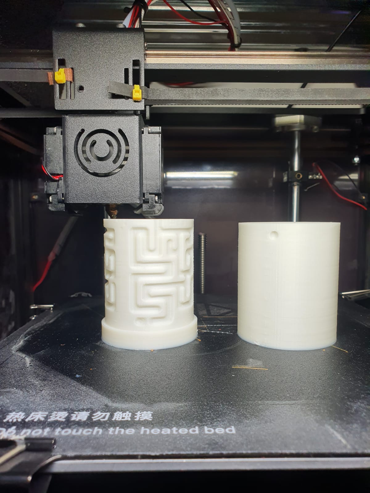
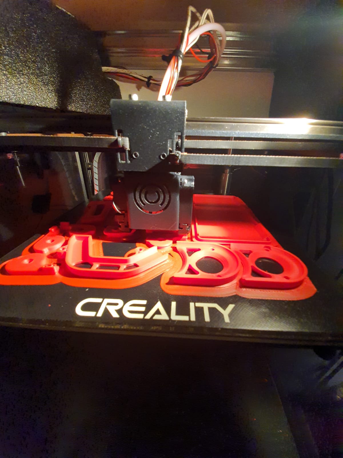
Since I am currently running 10 different 3d printers, my space is getting cramped in the house. I don’t want to expand into another room.  One should be enough. Having more printers gives me the best possible fit of a specific  filament type per printer.

The Voron is due to its perfect prints with ABS really only used for/with ABS or nylon.

The I3Bear dual carriage works best with dual PLA or PLA&PVA.

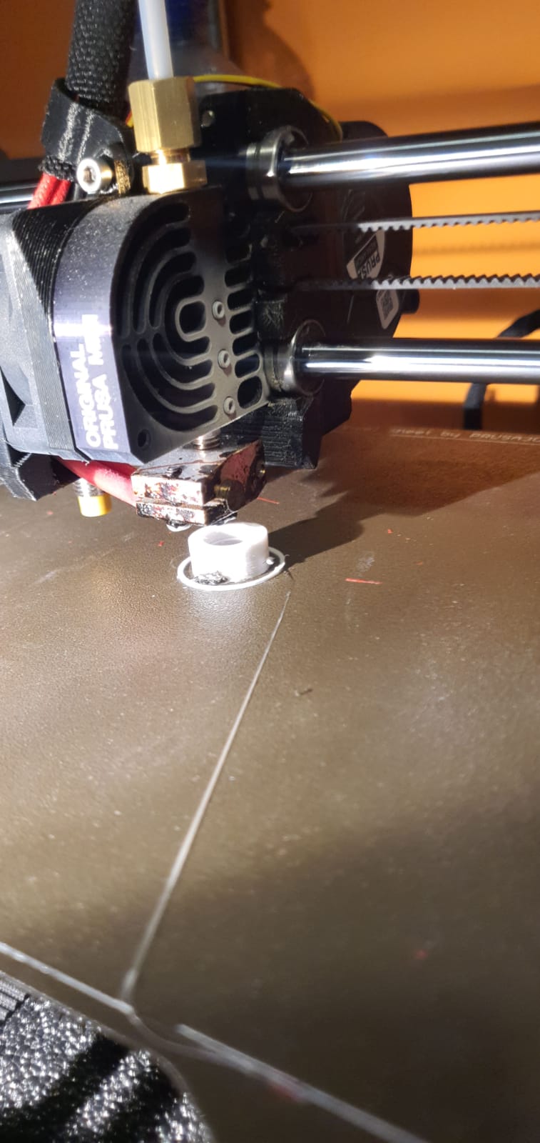
The Prusa mini works perfect with PETG

The I3Bear solo goes perfect with PETG or PLA.

The A30M & its mixing extruder goes perfect with PLA and/or PETG

And so on….

Our 3d printers, managed by OCTOPI and Duet Web Controller

Above: Our Dual Bear I3 dual color 3d printer with independant carriages, this one does not run octopi and is remotely managed by Duet Web Control (DWC).

Above: The Voron 2.4, dimensions 300x300x220 mm

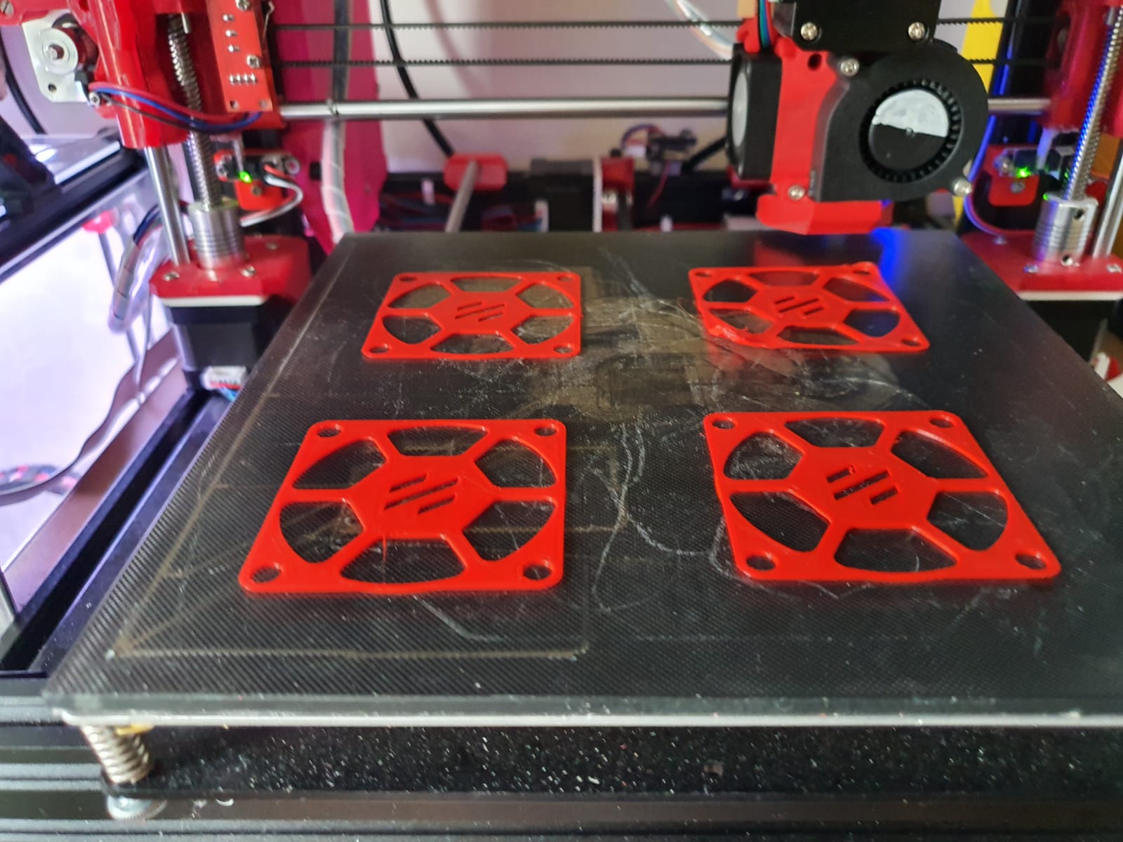
Prusa Bear I3plus with mods like dual Z axis control. This printer runs Duet and  DWC.


Kingroon Kp3S heavily modded with new firmware and tool fan. This printer runs with Octopi for remote management.


Twotrees Sapphire PRO with new firmware, also with octopi.


Voron 2.4 for Nylon and ABS printing, with external exhaust and 300+ degC printhead, bed up to 150 degC.  Also runs octopi.


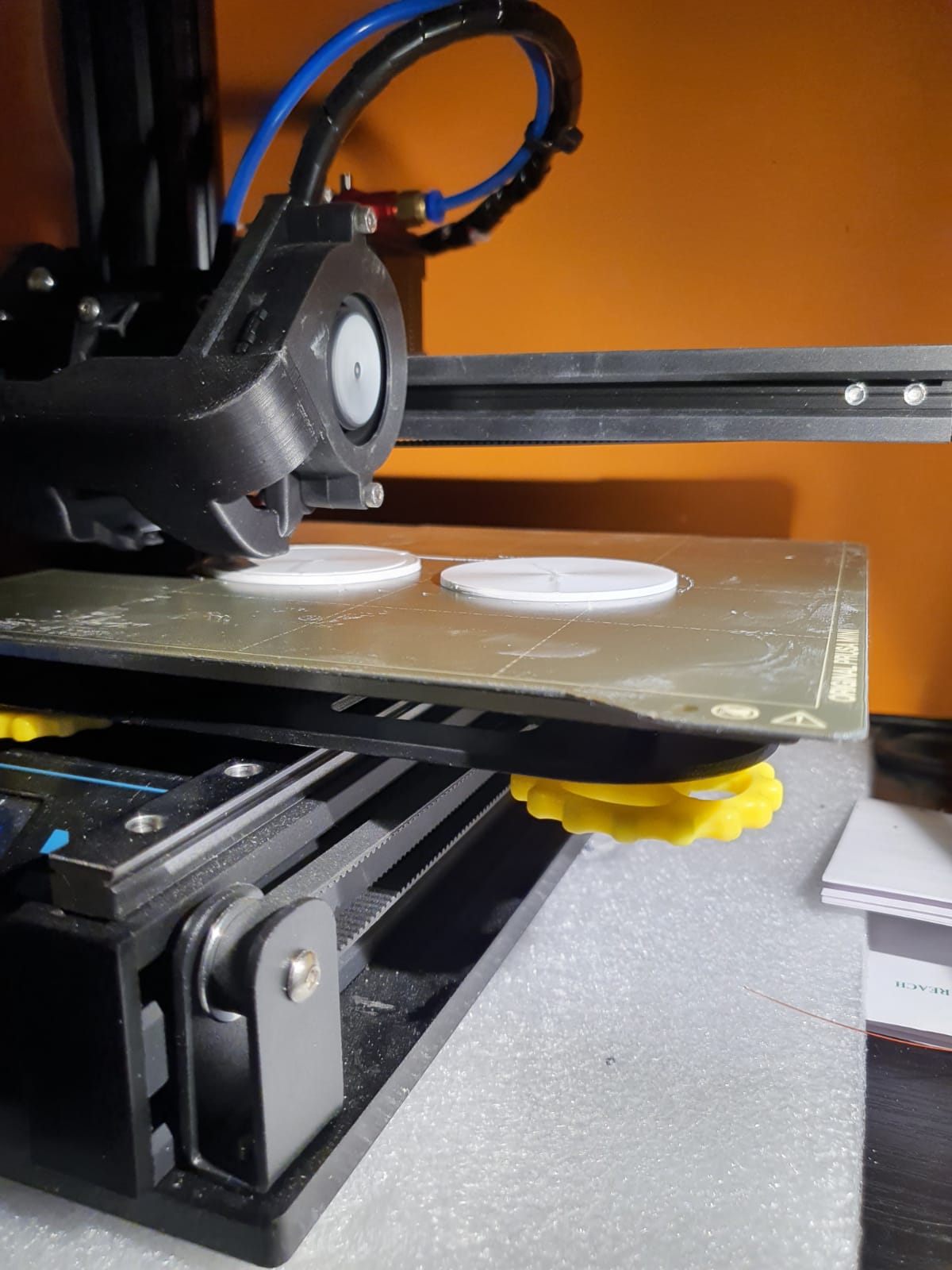
Prusa i3 mini original, the production monster for PETG. Also on octopi.


And the Twotrees Sapphire pro, our perfect printer for fast production, also on octopi.


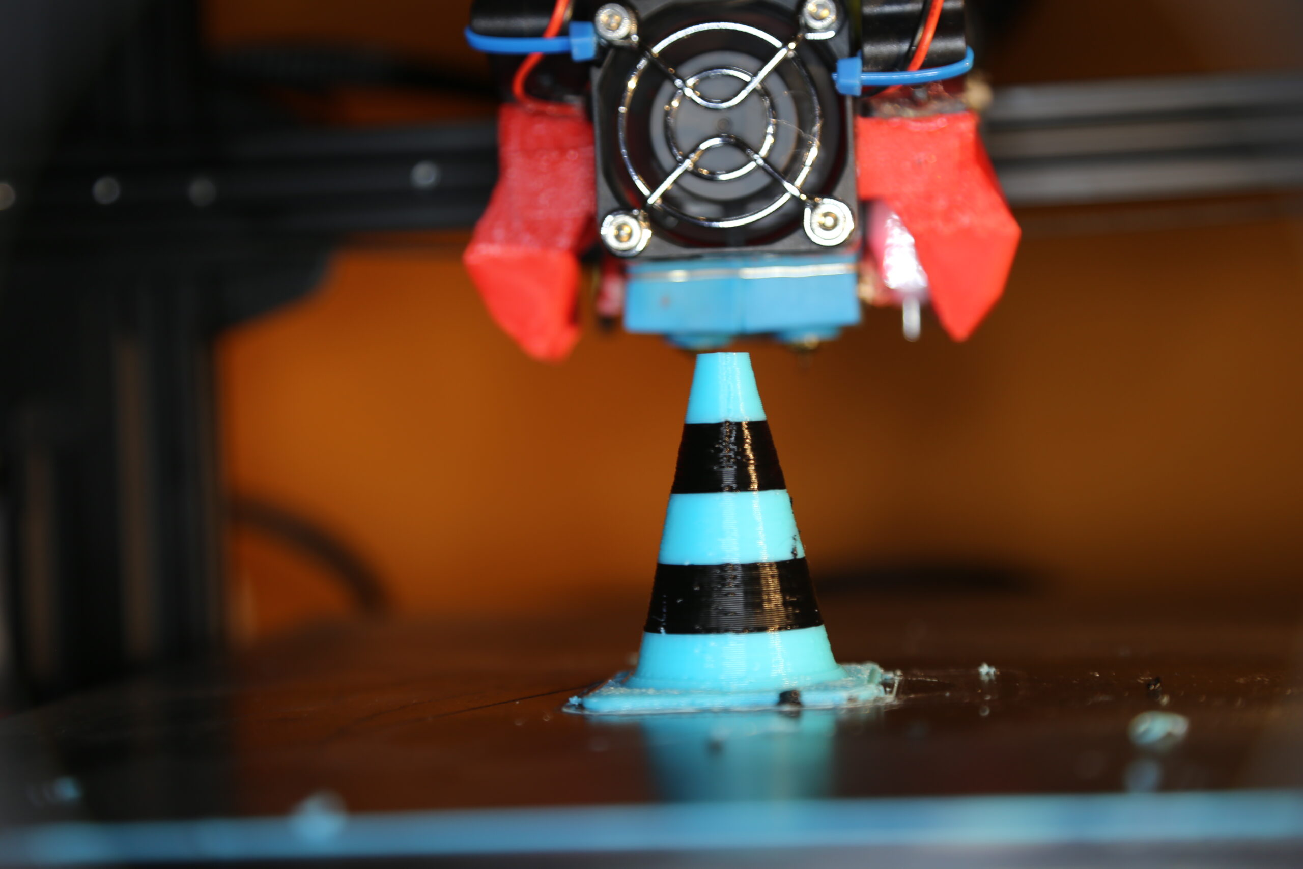
And the multicolour completely rebuilt Geeetech A30M dual head printer with a new Duet2Wifi motherboard, dual Chimera heatblock and direct drive extruders.  This one runs Duet with DWC instead of Octopi.


Our 3d printers, managed by OCTOPI OR Duet’s web-based app

Above: Our Dual Bear I3 dual color 3d printer with independant carriages, remotely managed by DUET’s webinterface

The Octopi solution works with a Raspberry PI, and on it the Octopi firmware.  The device you set up on your wifi and you connect it to your 3d printer’s USB. Then you have a web interface on the Raspberry’s IP address that allows you to manage all the things about your connected printer.  All the settings like temperature, mesh, and basically anything else you can manage through a local LCD.  And- you can upload your jobs to the raspberry and start/manage and adjust temperature and such.  What I really like is that you can connect a raspberry camera and follow your jobs.

The Duet I find in use and possibilities more pleasant. because in addition to everything that the octopi can, you can also modify the system files online.  And printer updates can do, directly in the firmware.  Moreover, you do not need a separate box because the Duet2wifi already has everything on board.

The disadvantage is that you can’t attach a camera to the Duet. There is a possibility em an IP camera to integrate into the DWC, Duet’s web based remote app.  And such a wifi IP camera is easy to make yourself with a cheap esp unit.


Above: The Voron 2.4, dimensions 300x300x220 mm

Prusa Bear I3plus with mods dual Z axis control


Kingroon Kp3S heavily modded with new firmware and tool fan


Twotrees Sapphire PRO with new firmware


Voron 2.4 for Nylon and ABS printing, with external exhaust and 300+ degC printhead, bed up to 150 degC


Prusa i3 mini original, the production monster for PETG


And the Twotrees Sapphire pro, our perfect printer for fast production


And the multicolour completely rebuilt Geeetech A30M dual head printer with a new Duet2Wifi motherboard, dual Chimera heatblock and direct drive extruders


error: Content is protected !!