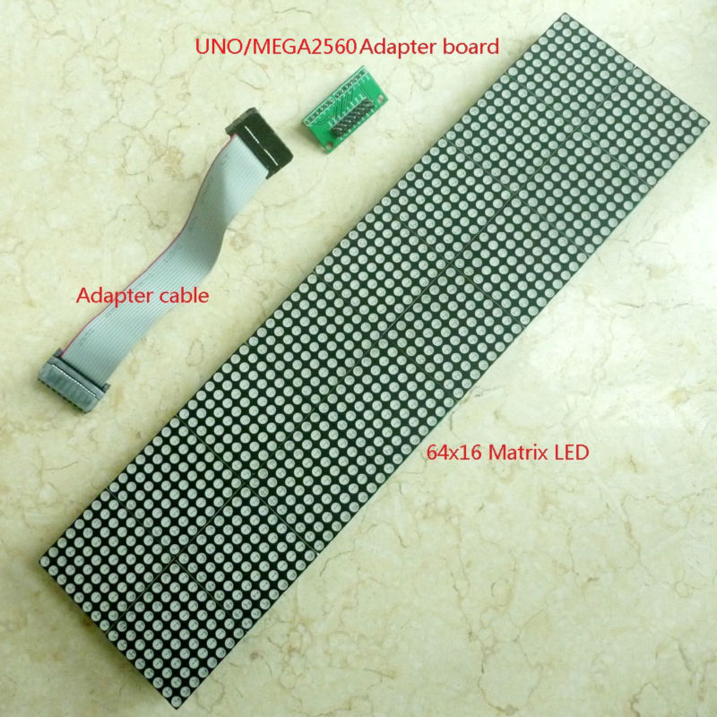
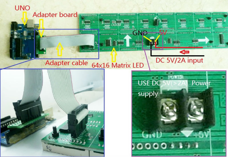
Module No.: TB275
//#include <AT24Cxx.h>//no lib needed since we will only use basic functions in 1 page at first
// Author: Phil Kaziewicz 19th July 2014,
// Jan Griffioen did quite some ADDITIONS july-nov 2014 such as RTC, temp, humidity, barmetric pressure, stringtext in time, funny roll-ups etc and voidstructuring
// 64×16 LED display matrix test code
// based upon original code from canton-electonics
// Arduino 1.0.6 NANO V4.0 (with the 2008 Windows drivers; these work with W8.1;
// add buttons or wire bridges for intensity (if possible), speed, language, time up and time down (both last buttons work more agressively when kept pushing…)
// will also try to adapt rotary switches for settings…
// D9& D?? are free for this
// A1 and A3, A6 and higher are free for this, preferrably with a resistor network like on the LCD shields, that should only consume 1 A-pin…
// Add a device for proximity and connect to a ‘button’ input for something like speed or intensity// crash,…
// The development is done with a Nano, after all is OK the pro mini will be glued to the rear of the board and one time programmed via a USB to TTL converter.
// Re-programming only on request!
#include <dht.h>
// Example testing sketch for various DHT humidity/temperature sensors
// Written by ladyada, public domain
#define DHTPIN 16 // what pin we’re connected to; A2=D16
// Uncomment whatever type you’re using!
#define DHTTYPE DHT11 // DHT 11
//#define DHTTYPE DHT22 // DHT 22 (AM2302)
//#define DHTTYPE DHT21 // DHT 21 (AM2301)
// Connect pin 1 (on the left) of the sensor to +5V
// NOTE: If using a board with 3.3V logic like an Arduino Due connect pin 1
// to 3.3V instead of 5V! with shield 5V is OK
// Connect pin 2 of the sensor to whatever your DHTPIN is
// Connect pin 4 (on the right) of the sensor to GROUND
// Connect a 10K resistor from pin 2 (data) to pin 1 (power) of the sensor
// Initialize DHT sensor for normal 16mhz Arduino
DHT dht(DHTPIN, DHTTYPE, 10);
// NOTE: For working with a faster chip, like an Arduino Due or Teensy, you
// might need to increase the threshold for cycle counts considered a 1 or 0.
// You can do this by passing a 3rd parameter for this threshold. It’s a bit
// of fiddling to find the right value, but in general the faster the CPU the
// higher the value. The default for a 16mhz AVR is a value of 6. For an
// Arduino Due that runs at 84mhz a value of 30 works.
// Example to initialize DHT sensor for Arduino Due:
//DHT dht(DHTPIN, DHTTYPE, 30);
//inputs for the select switches are: A1= Select, D9= Up and D7= Down
#define SelectPIN 15 //(=A1 when used digital) // what pin we’re connected to input for the select switch: A1= Select
#define UpPIN 9 // what pin we’re connected to input for the select switch: D9= Up
#define DownPIN 7 // what pin we’re connected to input for the select switch: D7= Down
#include <avr/pgmspace.h>
#include <Wire.h>
byte high = 0x00, low=0x00;//used for the AT24C32 chip addressing, no lib needed here
#include “RTClib.h”
RTC_DS1307 rtc; // this time module 1307 is connected to SCL (A5 on Nano) and SDA (A4 on Nano)
//#define AT24C32 0x50 //no lib needed here , address is correct though
boolean (Select)=false;
boolean (Up)=false;
boolean (Down)=false;
boolean (DEBUG)=true;
#define BMP085_ADDRESS 0x77 // I2C address of barometer BMP085 for barometer/temp/hight; this is also connected to SCL (A5 on Nano) and SDA (A4 on Nano)
const unsigned char OSS = 0; // Oversampling Setting
// Calibration values
int ac1;
int ac2;
int ac3;
unsigned int ac4;
unsigned int ac5;
unsigned int ac6;
int b1;
int b2;
int mb;
int mc;
int md;
//int wait; //, integer between 7 and 18, memory chip position low 1 and 2
int typeofclock; //, small clock or big clock 0 or 1 position low 3
int fun; //, with fun or just readouts 0 or 1 position low 3
int minormax; //, minimum screen or all of it 0 or 1 position low 4
int matrixwidth = 64;
int matrixheight = 16;
// b5 is calculated in bmp085GetTemperature(…), this variable is also used in bmp085GetPressure(…)
// so …Temperature(…) must be called before …Pressure(…).
long b5;
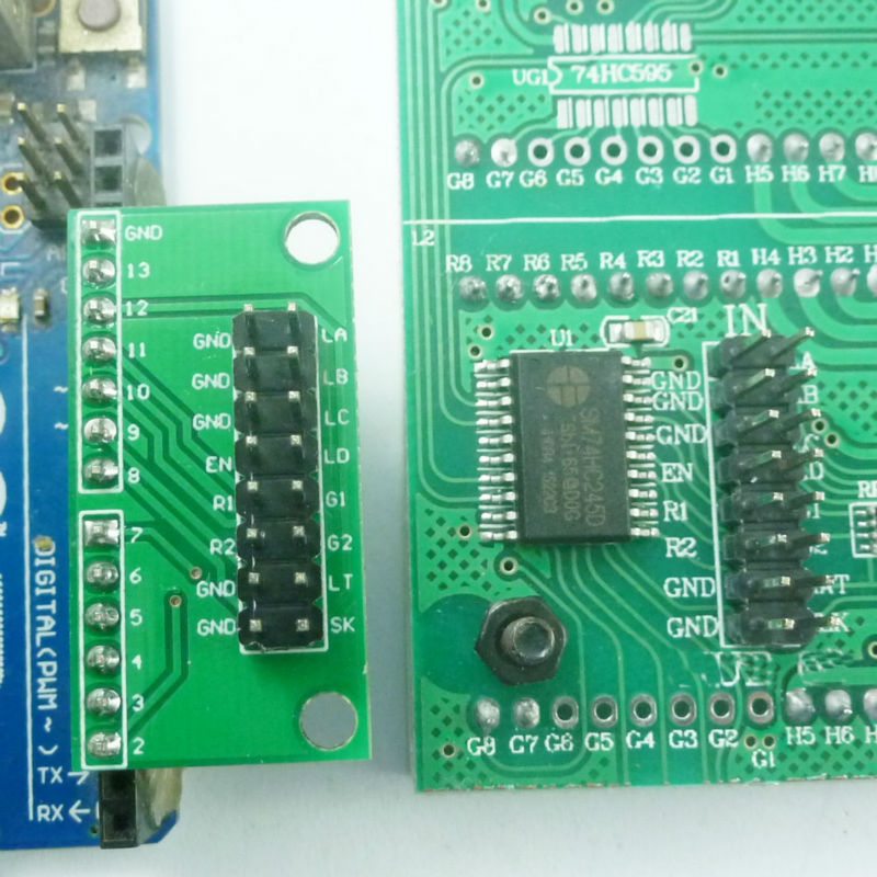
// Connections to board
const byte latchPin = 8;
const byte clockPin = 12;
const byte data_R1 = 10;
const byte data_R2 = 11;
const byte en_74138 = 2;
const byte la_74138 = 3;
const byte lb_74138 = 4;
const byte lc_74138 = 5;
const byte ld_74138 = 6;
byte ScanRow = 0;
unsigned long counter;
const int pinRandom = A0; // better to get this than use the standard C randomizer.. A0 can be freed if needed for anything else….
//const int wait = 100; // In milliseconds
const int length = 8;
int x[length], y[length];
int ptr, nextPtr;
int wait = 12; // In milliseconds (15 is nice), must be between 8 and 18
//int inc = -1;
int resetcounter=1;
//int waittemp = 15;
// declare the strings:
//String Shour,Shour1,Sminute,SdayOfWeek,Sday,Smonth,Sdate,Syear,ENtijd,Sminutesingle,Stotal;
/* #######################################
# RTC_DS1307 Datatypes (KEYWORD1)
#######################################
DateTime KEYWORD1
RTC_DS1307 KEYWORD1
RTC_Millis KEYWORD1
#######################################
# Methods and Functions (KEYWORD2)
#######################################
year KEYWORD2
month KEYWORD2
day KEYWORD2
hour KEYWORD2
minute KEYWORD2
second KEYWORD2
dayOfWeek KEYWORD2
secondstime KEYWORD2
unixtime KEYWORD2
begin KEYWORD2
adjust KEYWORD2
isrunning KEYWORD2
now KEYWORD2
#######################################
# Constants (LITERAL1)
#######################################
*/
char* dayNameEN[] = {
“g “, “Monday”, “Tuesday”, “Wednesday”, “Thursday”, “Friday”, “Saturday”, “Sunday”};
char* hourNameEN[] = {“twelve”, “one”, “two”, “three”, “four”, “five”, “six”, “seven”, “eight”, “nine”, “ten”, “eleven”, “twelve”, “one”};
// “two”, “three”, “four”, “five”, “six”, “seven”, “eight”, “nine”, “ten”, “eleven”, “twelve”};
char* monthNameEN[] = {“G “, ” January”, “February”, “March”, “April”, “May”, “June”, “July”, “August”, “September”, “October”, “November”, “December”};
byte buffer[256] = { // Display buffer (which is scanned by the interrupt timer) of 8×32 bytes
0x00, 0x00, 0x00, 0x00, 0x00, 0x00, 0x00, 0x00, 0x00, 0x00, 0x00, 0x00, 0x00, 0x00, 0x00, 0x00,
0x00, 0x00, 0x00, 0x00, 0x00, 0x00, 0x00, 0x00, 0x00, 0x00, 0x00, 0x00, 0x00, 0x00, 0x00, 0x00,
0x00, 0x00, 0x00, 0x00, 0x00, 0x00, 0x00, 0x00, 0x00, 0x00, 0x00, 0x00, 0x00, 0x00, 0x00, 0x00,
0x00, 0x00, 0x00, 0x00, 0x00, 0x00, 0x00, 0x00, 0x00, 0x00, 0x00, 0x00, 0x00, 0x00, 0x00, 0x00,
0x00, 0x00, 0x00, 0x00, 0x00, 0x00, 0x00, 0x00, 0x00, 0x00, 0x00, 0x00, 0x00, 0x00, 0x00, 0x00,
0x00, 0x00, 0x00, 0x00, 0x00, 0x00, 0x00, 0x00, 0x00, 0x00, 0x00, 0x00, 0x00, 0x00, 0x00, 0x00,
0x00, 0x00, 0x00, 0x00, 0x00, 0x00, 0x00, 0x00, 0x00, 0x00, 0x00, 0x00, 0x00, 0x00, 0x00, 0x00,
0x00, 0x00, 0x00, 0x00, 0x00, 0x00, 0x00, 0x00, 0x00, 0x00, 0x00, 0x00, 0x00, 0x00, 0x00, 0x00,
0x00, 0x00, 0x00, 0x00, 0x00, 0x00, 0x00, 0x00, 0x00, 0x00, 0x00, 0x00, 0x00, 0x00, 0x00, 0x00,
0x00, 0x00, 0x00, 0x00, 0x00, 0x00, 0x00, 0x00, 0x00, 0x00, 0x00, 0x00, 0x00, 0x00, 0x00, 0x00,
0x00, 0x00, 0x00, 0x00, 0x00, 0x00, 0x00, 0x00, 0x00, 0x00, 0x00, 0x00, 0x00, 0x00, 0x00, 0x00,
0x00, 0x00, 0x00, 0x00, 0x00, 0x00, 0x00, 0x00, 0x00, 0x00, 0x00, 0x00, 0x00, 0x00, 0x00, 0x00,
0x00, 0x00, 0x00, 0x00, 0x00, 0x00, 0x00, 0x00, 0x00, 0x00, 0x00, 0x00, 0x00, 0x00, 0x00, 0x00,
0x00, 0x00, 0x00, 0x00, 0x00, 0x00, 0x00, 0x00, 0x00, 0x00, 0x00, 0x00, 0x00, 0x00, 0x00, 0x00,
0x00, 0x00, 0x00, 0x00, 0x00, 0x00, 0x00, 0x00, 0x00, 0x00, 0x00, 0x00, 0x00, 0x00, 0x00, 0x00,
0x00, 0x00, 0x00, 0x00, 0x00, 0x00, 0x00, 0x00, 0x00, 0x00, 0x00, 0x00, 0x00, 0x00, 0x00, 0x00,
};
#include <fontsBIGREDLED.h>
// xxxxxxxxxxxxxxxxxxxxxxxxxxxxxxxxxxxxxxxxxxxxxxxxxxxxxxxxxxxxxxxxxxxxxxxxxxxxxxxxxxxxxxxxxxxxxxxxxxxxxxxxxxxxxxxxxxxxxxx
// Routine to print a single character in one of 8 columns
// Inputs:
// x is one of (0,16,24,32,40,48,56), for shifting purposes 64 should als be available….
// y (0 to 16 or 24 depending upon font size),
// n is either (0 to 9) or an ascii value, ascii as ([“”])??
// font=0 for big font, 2 for small font,
// inverse is true for an inverted character
void drawChar(uint16_t x, uint16_t y, byte n, byte font, boolean inverse) {
byte charbytes[16], fontrows, xover8 = x >> 3;
int index;
if (0 != (x % 8)) return; // x not a multiple of 8
if ((n > 9) && (n < 32)) return; // invalid character
if (font == 2) fontrows = 16; else fontrows = 8;
if ((n >= 0) && (n <= 9)) index = (n + 16) * fontrows; else index = (n – 32) * fontrows; // go to the right code for this character
// addressing start at buffer and add y (rows) * (WIDTH is 64 so WIDTH/8) is 8 plus (x / 8) is 0 to 7
byte *pDst = buffer + (y << 3) + xover8;
for (byte i = 0; i < fontrows; i++) { // fill up the charbytes array with the right bits
if (font == 0) charbytes[i] = pgm_read_byte(&(font8x8_basic[index + i]));
// if (font==1) charbytes[i] = pgm_read_byte(&(font8x8_extended[index+i]));
if (font == 2) charbytes[i] = pgm_read_byte(&(font8x16_basic[index + i]));
// reverse bit order for fonts 0 and 1
if (font != 2) {
charbytes[i] = (charbytes[i] & 0xF0) >> 4 | (charbytes[i] & 0x0F) << 4;
charbytes[i] = (charbytes[i] & 0xCC) >> 2 | (charbytes[i] & 0x33) << 2;
charbytes[i] = (charbytes[i] & 0xAA) >> 1 | (charbytes[i] & 0x55) << 1;
};
if (inverse) charbytes[i] = ~charbytes[i];
};
const byte *pSrc = charbytes; // point at the first set of 8 pixels
for (byte i = 0; i < fontrows; i++) {
*pDst = *pSrc; // populate the destination byte
pDst += 8; // go to next row on buffer
pSrc++; // go to next set of 8 pixels in character
}
};
// xxxxxxxxxxxxxxxxxxxxxxxxxxxxxxxxxxxxxxxxxxxxxxxxxxxxxxxxxxxxxxxxxxxxxxxxxxxxxxxxxxxxxxxxxxxxxxxxxxxxxxxxxxxxxxxxxxxxxxx
void moveLeft(byte pixels, byte rowstart, byte rowstop) { // routine to move certain rows on the screen “pixels” pixels to the left
byte row, column;
short unsigned int address;
for (column = 0; column < 8; column++) {
for (row = rowstart; row < rowstop; row++) {
address = (row << 3) + column; /// right here!
if (column == 7)
buffer[address] = buffer[address] << pixels; // shuffle pixels left on last column and fill with a blank
else { // shuffle pixels left and add leftmost pixels from next column
byte incomingchar = buffer[address + 1];
buffer[address] = buffer[address] << pixels;
for (byte x = 0; x < pixels; x++) {
buffer[address] += ((incomingchar & (128 >> x)) >> (7 – x)) << (pixels – x – 1);
};
}
}
}
};
// xxxxxxxxxxxxxxxxxxxxxxxxxxxxxxxxxxxxxxxxxxxxxxxxxxxxxxxxxxxxxxxxxxxxxxxxxxxxxxxxxxxxxxxxxxxxxxxxxxxxxxxxxxxxxxxxxxxxxxx
// set a single pixel on or off
void setPixel(byte x, byte y, byte colour) {
bitWrite(buffer[(y << 3) + (x >> 3)], 7 – (x & 7), colour);
};
// xxxxxxxxxxxxxxxxxxxxxxxxxxxxxxxxxxxxxxxxxxxxxxxxxxxxxxxxxxxxxxxxxxxxxxxxxxxxxxxxxxxxxxxxxxxxxxxxxxxxxxxxxxxxxxxxxxxxxxx
void drawRect(byte x1, byte y1, byte x2, byte y2, byte colour) {
for (byte x = x1; x <= x2; x++) {
setPixel(x, y1, colour);
setPixel(x, y2, colour);
};
for (byte y = y1; y <= y2; y++) {
setPixel(x1, y, colour);
setPixel(x2, y, colour);
};
};
//start VOID =====================================================================================
void drawLine(byte x1, byte y1, byte x2, byte y2, byte colour) {
//Draws a line, between the points (x1, y1) and (x2, y2) in this graphics context’s coordinate system.
//Parameters:
// x1 – the first point’s x coordinate.
// y1 – the first point’s y coordinate.
// x2 – the second point’s x coordinate.
// y2 – the second point’s y coordinate.
for (byte x = x1; x <= x2; x++) {
setPixel(x, y1, colour);
setPixel(x, y2, colour);
};
for (byte y = y1; y <= y2; y++) {
setPixel(x1, y, colour);
setPixel(x2, y, colour);
};
};
// xxxxxxxxxxxxxxxxxxxxxxxxxxxxxxxxxxxxxxxxxxxxxxxxxxxxxxxxxxxxxxxxxxxxxxxxxxxxxxxxxxxxxxxxxxxxxxxxxxxxxxxxxxxxxxxxxxxxxxx
void shiftOut(byte row) { // fast routine to shove out 8 columns into two rows via board’s shift registers
for (byte column = 0; column < 8; column++) {
byte index = column + (row << 3);
for (byte i = 0; i < 8; i++) {
PORTB &= ~(3 << (data_R1 – 8)); // data_R2 is LOW; data_R1 is LOW;
PORTB &= ~(1 << (clockPin – 8)); // digitalWrite(clockPin,LOW);
PORTB |= !((buffer[index] >> (7 – i)) & 0x01) << (data_R1 – 8); // top set of rows
PORTB |= !((buffer[index + 128] >> (7 – i)) & 0x01) << (data_R2 – 8); // bottom set of rows
PORTB |= 1 << (clockPin – 8); // digitalWrite(clockPin,HIGH);
};
};
};
// Scan a pair of rows on to the display from “buffer” via the interrupt
ISR(TIMER2_COMPA_vect) {
cli();
digitalWrite(en_74138, HIGH); // Turn off display
shiftOut(ScanRow); // Shift out 8 columns
digitalWrite(latchPin, LOW);
digitalWrite(latchPin, HIGH);
PORTD = (ScanRow << 3) | (PORTD & 0X87); // Highlight row: pins 3 4 5 6 (la_74138 lb_74138 lc_74138 ld_74138)
digitalWrite(en_74138, LOW); // Turn on display
ScanRow++; // Do the next pair of rows next time this routine is called
if (ScanRow == 16) ScanRow = 0;
sei();
};
//start VOID =====================================================================================
void wacht(int wachttijd)
{
for (int a = 0; a < wachttijd; a++ )
{
int val = digitalRead(SelectPIN); // must be Select read the input pin
if (val==LOW) // if key Select is pressed
{
Select=true; // set a binary state high here , then
return; //return to loop;
}
delay(1);
}
}
//======================================================================================================================================================
//void(* resetFunc) (void) = 0;//declare reset function at address 0
//======================================================================================================================================================
void runscreen(String Stotal)
{
int stringlength= (Stotal.length()+1);//+1
char timestring[stringlength];
Stotal.toCharArray(timestring,(stringlength));
static int count = 0;
for (int count = 0; count <= sizeof(timestring) -2; count++)//was timestring-1 but then there is 1 blank space in front of each roll
{
drawChar(56, 0, timestring[count % (sizeof(timestring)-1 )], 2, false);//timestring-1
// drawChar(56, 8, timestring[count % (sizeof(timestring)-1 )], 0, false);//timestring-1
for (byte i = 0; i < 9; i++)// move the text 9 pixels (not 8 because it looks better) to the left
{
moveLeft(1, 2, 32);
wacht(wait);
}
}
}
//XXXXXXXXXXXXXXXXXXXXXXXXXXXXXXXXXXXXXXXXXXXXXXXXXXXXXXXXXXXXXXXXXXXXXXXXXXXXXXXXXXXXXXXXXXXXXXXXXXXXXXXXXXXXXXXXXXXXXXXXXXXXXXXXXXXXXXXXXXXXX
void writescreensmall(String above, String under, int height)
{
char letter;
int aa;
int a;
for (a = 0; a < 8; a++ )
{letter = above.charAt(a);
aa=8*a;
drawChar(aa, height, (letter), 0, false);
}
for (a = 0; a < 8; a++ )
{letter = under.charAt(a);
aa=8*a;
drawChar(aa, 8, (letter), 0, false);
}
}
//XXXXXXXXXXXXXXXXXXXXXXXXXXXXXXXXXXXXXXXXXXXXXXXXXXXXXXXXXXXXXXXXXXXXXXXXXXXXXXXXXXXXXXXXXXXXXXXXXXXXXXXXXXXXXXXXXXXXXXXXXXXXXXXXXXXXXXXXXXXXX
void writescreenbig(String above, int height)
{
char letter;
int aa;
int a;
for (a = 0; a < 8; a++ )
{letter = above.charAt(a);
aa=8*a;
drawChar(aa, height, (letter), 2, false);
}
}
//XXXXXXXXXXXXXXXXXXXXXXXXXXXXXXXXXXXXXXXXXXXXXXXXXXXXXXXXXXXXXXXXXXXXXXXXXXXXXXXXXXXXXXXXXXXXXXXXXXXXXXXXXXXXXXXXXXXXXXXXXXXXXXXXXXXXXXXXXXXXXXXX
void setup() {
if (Select)switches() ; // if key select is pressed it is detected in void wait and returned to loop; from there to void switches…
pinMode(SelectPIN, INPUT); // N.O. push button switch
pinMode(UpPIN, INPUT); // N.O. push button switch
pinMode(DownPIN, INPUT); // N.O. push button switch
digitalWrite(SelectPIN, HIGH); // pull-ups on
digitalWrite(UpPIN, HIGH);// pull-ups on
digitalWrite(DownPIN, HIGH); // pull-ups on
Serial.begin(9600);
// InitDHT();//Does what’s necessary to prepare for reading DHT
dht.begin();
//delay(1300); // needed for DHT11
#ifdef AVR
Wire.begin();
#else
Wire1.begin(); // Shield I2C pins connect to alt I2C bus on Arduino Due
#endif
rtc.begin();
if (! rtc.isrunning()) {
//Serial.println(“RTC is NOT running!”);
// following line sets the RTC to the date & time this sketch was compiled
rtc.adjust(DateTime(__DATE__, __TIME__));
}
// rtc.adjust(DateTime(__DATE__, __TIME__)); // Q&D way to set the time anyway but take it off the program afterwards!
for ( int ptr = 0; ptr < length; ptr++ ) {
x[ptr] = 16 ; //numberOfHorizontal8bitsDisplays * 8 / 2
y[ptr] = 16 ; //numberOfVertical8bitsDisplays * 8 / 2
}
nextPtr = 0;
// Serial.println(“Humidity and temperature\n\n”);
bmp085Calibration();
// Set up Timer2 as the scanning interrupt timer
cli(); // clear interrupts
TCCR2A = 0; TCCR2B = 0; TCNT2 = 0;
TCCR2B |= (1 << CS12) | (1 << CS10); // Set 1024 prescaler
// 160Hz scan rate = 10 frames/second (16 pairs of rows)
OCR2A = 97; // 97 = (16,000,000 / (1024*160)) – 1
TCCR2A |= (1 << WGM21); TIMSK2 |= (1 << OCIE2A);
pinMode(latchPin, OUTPUT); pinMode(clockPin, OUTPUT);
pinMode(data_R1, OUTPUT); pinMode(data_R2, OUTPUT);
pinMode(en_74138, OUTPUT);
pinMode(la_74138, OUTPUT); pinMode(lb_74138, OUTPUT);
pinMode(lc_74138, OUTPUT); pinMode(ld_74138, OUTPUT);
digitalWrite(en_74138, LOW);
digitalWrite(data_R1, HIGH); digitalWrite(data_R2, HIGH);
counter = millis();
sei(); //allow interrupts
//READ the memory of the AT24C32 (and write te settings he
low=0x00;
// Serial.println();
// Serial.print(“DATA SETUP VOID READ: “);
for (int i=0;i<=20;i++)
{
Wire.beginTransmission(0x50);
Wire.write(high);
Wire.write(low);
Wire.endTransmission();
Wire.requestFrom(0x50 ,1);
int data=Wire.read();//char or int, can both be done?
delay(5);
// Serial.print (data)-48;
// Serial.print(“,”);
// Serial.println(low);
// delay(10);
if (low==1) wait=int(data)-48+8;
if (low==2) typeofclock=int(data)-48;
if (low==3) fun=int(data)-48;
if (low==4) minormax=int(data)-48;
low++;
}
// the values of the settings will be written in AT24C32 register and will be read in Setup void, every time the device (re)starts
// the values are:
// wait, integer between 0 and 9==> 8 to 18 position low 1
// typeofclock, small clock or big clock 0 or 1 position low 2
// fun, with fun or just readouts 0 or 1 position low 3
// minormax, minimum screen or all of it 0 or 1 position low 4
// Serial.println();
// Serial.print(” Transferred to program: wait= “);
// Serial.print(wait);
// Serial.print(“, typeofclock= “);
// Serial.print(typeofclock);
// Serial.print(“, fun= “);
// Serial.print(fun);
// Serial.print(“, minormax= “);
// Serial.print(minormax);
// Serial.println();
}
// Note that there’s no need to do anything with the screen in the main loop.
// Whatever’s in “buffer” is constantly scanned out.
//======================================================================================================================================================
void loop() {
// bmp085Calibration();
//delay(2000);
if (Select)switches() ; // if key select is pressed it is detected in void wait and returned to loop; from there to void switches…
// Reading temperature or humidity takes about 250 milliseconds!
// Sensor readings may also be up to 2 seconds ‘old’ (its a very slow sensor)
//float h = dht.readHumidity();
// Read temperature as Celsius
// float t = dht.readTemperature();
// Read temperature as Fahrenheit
// float f = dht.readTemperature(true);
// Check if any reads failed and exit early (to try again).
// if (isnan(h) || isnan(t) || isnan(f)) {
// Serial.println(“Failed to read from DHT sensor!”);
// return;
// }
// Compute heat index
// Must send in temp in Fahrenheit!
// float hi = dht.computeHeatIndex(f, h);
// float temperature = bmp085GetTemperature(bmp085ReadUT()); //MUST be called first
// float pressure = bmp085GetPressure(bmp085ReadUP());
// float atm = pressure / 101325; // “standard atmosphere”
// float altitude = calcAltitude(pressure); //Uncompensated caculation – in Meters
// Serial.print(“Humidity: “);
// Serial.print(h);
// Serial.print(” %\t”);
// Serial.print(“Temperature: “);
// Serial.print(t);
// Serial.print(” *C “);
// Serial.print(f);
// Serial.print(” *F\t”);
// Serial.print(“Heat index: “);
// Serial.print(hi);
// Serial.println(” *F”);
// Serial.println();//line break
// Serial.print(“Temperature: “);
// Serial.print(temperature, 2); //display 2 decimal places
// Serial.println(“deg C”);
// Serial.print(“Pressure: “);
// Serial.print(pressure, 0); //whole number only.
// Serial.println(” Pa (100 Pa = 1 millibar)”);
// Serial.print(“Standard Atmosphere: “);
// Serial.println(atm, 4); //display 4 decimal places
// Serial.print(“Altitude: “);
// Serial.print(altitude, 2); //display 2 decimal places
// Serial.println(” M”);
// Serial.println();//line break
// clearscreen();
// if (resetcounter == 4)resetFunc(); //call reset
// resetcounter=resetcounter+1;
clearscreen();
rollingtimeEN();
if (Select)switches() ; // if key select is pressed it is detected in void wait and returned to loop; from there to void switches…
rollingdateEN();
if (Select)switches() ; // if key select is pressed it is detected in void wait and returned to loop; from there to void switches…
runscreen(” “); //shiftout the display with blanks
clearscreen();
JMWG();
clearscreen();
if (typeofclock==0) return;
if (Select)switches() ; // if key select is pressed it is detected in void wait and returned to loop; from there to void switches…
if (typeofclock==0) return;
// clearscreen();
// writescreensmall (” Plaats “, ” je “,0);
// wacht(wait*140);
// if (Select)switches() ; // if key select is pressed it is detected in void wait and returned to loop; from there to void switches…
// writescreenbig (” Eigen “, 0);
// wacht(wait*140);
// if (Select)switches() ; // if key select is pressed it is detected in void wait and returned to loop; from there to void switches…
// writescreensmall (” tekst “, ” hier! “,0);
// wacht(wait*140);
// if (Select)switches() ; // if key select is pressed it is detected in void wait and returned to loop; from there to void switches…
clearscreen();
rollinghumidEN();
if (Select)switches() ; // if key select is pressed it is detected in void wait and returned to loop; from there to void switches…
rollingTempENF();
if (Select)switches() ; // if key select is pressed it is detected in void wait and returned to loop; from there to void switches…
rollingTempENC();
if (Select)switches() ; // if key select is pressed it is detected in void wait and returned to loop; from there to void switches…
rollingPressureEN();
if (Select)switches() ; // if key select is pressed it is detected in void wait and returned to loop; from there to void switches…
rollingHeightEN();
if (Select)switches() ; // if key select is pressed it is detected in void wait and returned to loop; from there to void switches…
clearscreen();
bigclock();
if (Select)switches() ; // if key select is pressed it is detected in void wait and returned to loop; from there to void switches…
clearscreen();
JMWG();
if (Select)switches() ; // if key select is pressed it is detected in void wait and returned to loop; from there to void switches…
clearscreen();
rollingtimeEN();
runscreen(” “); //shiftout the display with blanks
if (Select)switches() ; // if key select is pressed it is detected in void wait and returned to loop; from there to void switches…
clearscreen();
snake();
if (Select)switches() ; // if key select is pressed it is detected in void wait and returned to loop; from there to void switches…
clearscreen();
rollupclock();
if (Select)switches() ; // if key select is pressed it is detected in void wait and returned to loop; from there to void switches…
clearscreen();
JMWG();
if (Select)switches() ; // if key select is pressed it is detected in void wait and returned to loop; from there to void switches…
// wait = wait + inc;
// if ( wait < 8 ) inc = 1; //random(15,2);
// if ( wait > 15 ) inc = -1; //-random(15,2);
// wait=random (18,8);
};
//xxxxxxxxxxxxxxxxxxxxxxxxxxxxxxxxxxxxxxxxxxxxxxxxxxxxxxxxxxxxxxxxxxxxxxxxxxxxxxxxxxxxxxxxxxxxxxxxxxxxxxxxxxxxxxxxxxxx
void clearscreen()
// setPixel(x,y,colour) where if colour=0 pixel=off, if colour=1 pixel=on
{
int yy = 0;
int xx = 0;
for (yy = 0; yy <= 16; yy++)
{
for (xx = 0; xx <= 64; xx++)
{
setPixel(xx, yy, (0));
}
}
}
//======================================================================================================================================================
void rollingtimeEN()
{
DateTime now = rtc.now(); // Get data from the DS1307
int counthour;
if ( (int (now.hour())) > 11) {counthour = (int(now.hour())-12);}
else int counthour = int(now.hour());
String Shour = (hourNameEN[counthour]);
String Shour1 = (hourNameEN[(counthour+1)]);
int Sminutesingle = (now.minute());
String ENtijd = “Time ERROR”;
if ((Sminutesingle)==0) ENtijd = “exactly “+ Shour+ ” o’clock”;
else if ((Sminutesingle)==1) ENtijd = “1 minute past “+ Shour;
else if ((Sminutesingle)==15) ENtijd = “a quarter past “+ Shour;
// else if ((Sminutesingle)==29) ENtijd = “1 to half “+ Shour1;
else if ((Sminutesingle)==30) ENtijd = “half past “+ Shour;
// else if ((Sminutesingle)==31) ENtijd = “1 past half “+ Shour1;
else if ((Sminutesingle)==45) ENtijd = “a quarter to “+ Shour1;
else if ((Sminutesingle)==59) ENtijd = “1 minute to “+ Shour1;// + ” o’clock”;
else if (Sminutesingle > 1 && Sminutesingle < 29){ ENtijd = String(Sminutesingle)+ ” minutes past “+ Shour;}
else if (Sminutesingle > 31 && Sminutesingle < 59){ ENtijd = String(60-Sminutesingle)+ ” minutes to ” + Shour1;}
else if ((Sminutesingle)==60) ENtijd = “precisely “+ Shour1+ ” o’clock”;
else ENtijd =”Time ERROR”;
//define the timestring to be rolled here:
String Stotal = ” It is ” + ENtijd;
runscreen(Stotal);
}
//======================================================================================================================================================
void rollingdateEN()
{
DateTime now = rtc.now(); // Get data from the DS1307
String Sday = (dayNameEN[int(now.dayOfWeek())]);
String Sdate = String(now.day());
String Smonth = (monthNameEN[int(now.month())]);
String Syear = String(now.year()).substring(0,4);
String Stotal = “, ” + Sday + ‘ ‘ + Smonth + ‘ ‘ + Sdate + “, ” + Syear; //define the datestring to be rolled here
runscreen(Stotal);
clearscreen;
}
//start VOID =====================================================================================
void snake()
{
int matrixwidth = 64;
int matrixheight = 16;
for (int a = 0; a < (1000); a++) {
// Shift pointer to the next segment
ptr = nextPtr;
nextPtr = next(ptr);
setPixel(x[ptr], y[ptr], 1); // Draw the head of the snake
wacht(wait * 1);
if ( ! occupied(nextPtr) ) {
setPixel(x[nextPtr], y[nextPtr], 0); // Remove the tail of the snake
}
for ( int attempt = 0; attempt < 20; attempt++ ) {
// Jump at random one step up, down, left, or right
switch ( random(4) ) {
case 0: x[nextPtr] = constrain(x[ptr] + 1, 0, matrixwidth – 1); y[nextPtr] = y[ptr]; break;
case 1: x[nextPtr] = constrain(x[ptr] – 1, 0, matrixwidth – 1); y[nextPtr] = y[ptr]; break;
case 2: y[nextPtr] = constrain(y[ptr] + 1, 0, matrixheight – 1); x[nextPtr] = x[ptr]; break;
case 3: y[nextPtr] = constrain(y[ptr] – 1, 0, matrixheight – 1); x[nextPtr] = x[ptr]; break;
}
if ( ! occupied(nextPtr) ) {
break; // The spot is empty, break out the for loop
}
}
}
}
boolean occupied(int ptrA) {
for ( int ptrB = 0 ; ptrB < length; ptrB++ ) {
if ( ptrA != ptrB ) {
if ( equal(ptrA, ptrB) ) {
return true;
}
}
}
return false;
}
int next(int ptr) {
return (ptr + 1) % length;
}
boolean equal(int ptrA, int ptrB) {
return x[ptrA] == x[ptrB] && y[ptrA] == y[ptrB];
// wait=waittemp;
clearscreen();
}
//start VOID =====================================================================================
void bigclock()
{
clearscreen;
DateTime now = rtc.now(); // Date and time functions using a DS1307 RTC connected via I2C and Wire lib
// String Syear = String(now.year()).substring(2,4);
for (int aa = 0; aa <= 50; aa++)
{
DateTime now = rtc.now();
// writescreenbig ((String ((now.hour()/10) %10))+(String (now.hour()%10))+’:’+String((now.minute()/10) %10) + String(now.minute()%10)+’:’+ (String((now.second()/10)%10))+ String(now.second()%10),int((aa-25)/8));
writescreenbig ((String ((now.hour()/10) %10))+(String (now.hour()%10))+’:’+String((now.minute()/10) %10) + String(now.minute()%10)+’:’+ (String((now.second()/10)%10))+ String(now.second()%10),0);
wacht (wait*7);
writescreenbig ((String ((now.hour()/10) %10))+(String (now.hour()%10))+’ ‘+String((now.minute()/10) %10) + String(now.minute()%10)+’ ‘+ (String((now.second()/10)%10))+ String(now.second()%10),0);
// writescreenbig (String(now.hour()).substring(0,2)+’ ‘+ String(now.minute()).substring(0,2)+’ ‘+ String(now.second()).substring(0,2),int((aa-25)/8));
wacht (wait*7);
}
//clearscreen;
for (int aa = 0; aa <= 15; aa++)
{
DateTime now = rtc.now();
writescreenbig ((String ((now.day()/10) %10))+(String (now.day()%10))+’/’+String((now.month()/10) %10) + String(now.month()%10)+’/’+ String(now.year()).substring(2,4),0);
wacht (wait*5);
drawChar(16, -1, ‘-‘ , 2, false);
drawChar(40, -1, ‘-‘ , 2, false);
wacht (wait*5);
drawChar(16, -1, (92) , 2, false);
drawChar(40, -1, (92) , 2, false);
wacht (wait*5);
drawChar(16, -1, (124) , 2, false);
drawChar(40, -1, (124) , 2, false);
wacht (wait*5);
}
clearscreen;
}
//start VOID =====================================================================================
void rollupclock()
{
clearscreen();
DateTime now = rtc.now(); // Date and time functions using a DS1307 RTC connected via I2C and Wire lib
for (int aa = 17; aa >= 0; aa–)
{
DateTime now = rtc.now();
clearscreen();
writescreenbig ((String ((now.hour()/10) %10))+(String (now.hour()%10))+’:’+String((now.minute()/10) %10) + String(now.minute()%10)+’:’+ (String((now.second()/10)%10))+ String(now.second()%10),aa);
wacht (wait*2);
}
wacht(wait*100);
//for (int aa = 0; aa <= 17; aa++) //down and away
for (int aa = 0; aa >= -17; aa–) //up and away
{
clearscreen();
writescreenbig ((String ((now.hour()/10) %10))+(String (now.hour()%10))+’:’+String((now.minute()/10) %10) + String(now.minute()%10)+’:’+ (String((now.second()/10)%10))+ String(now.second()%10),aa);
wacht (wait*2);
}
clearscreen;
wacht(wait*30);
}
//start VOID =====================================================================================
void JMWG(){
int matrixwidth = 64;
int matrixheight = 16;
for (int a = 0; a < 1; a++ ) {
drawChar(16, 0, ‘J’, 2, false);
drawChar(24, 0, ‘M’, 2, false);
drawChar(32, 0, ‘W’, 2, false);
drawChar(40, 0, ‘G’, 2, false);
for ( int x = 0; x < matrixwidth – 1; x++ ) {
drawLine(x, 0, matrixwidth – 1 – x, matrixheight – 1, 1);
wacht(wait);
drawLine(x, 0, matrixwidth – 1 – x, matrixheight – 1, 0);
}
for ( int y = 0; y < matrixheight – 1; y++ ) {
drawLine(matrixwidth – 1, y, 0, matrixheight – 1 – y, 1);
wacht(wait);
drawLine(matrixwidth – 1, y, 0, matrixheight – 1 – y, 0);
}
}
}
//======================================================================================================================================================
void rollinghumidEN()
{
int Stemp = dht.readHumidity();// Get data from the temp and humid sensor
String Stotal=” The relative humidity is “+String(Stemp)+” percent,”; //define the humid string to be rolled
runscreen(Stotal);
}
//======================================================================================================================================================
void rollingTempENF()
{
float temperature = 32+ (1.8*(bmp085GetTemperature(bmp085ReadUT()))); // calculate to Fahrenheit= ((Celsius x 1.8) + 32)
String Stotal= ” the temperature is ” + String(temperature,1)+ ” degrees Fahrenheit,” ; //define the string to be rolled
runscreen (Stotal);
}
//======================================================================================================================================================
void rollingTempENC()
{
float temperature = bmp085GetTemperature(bmp085ReadUT()); // Celsius
String Stotal= ” (” + String(temperature,1)+ ” degrees Celsius),” ; //define the string to be rolled
runscreen (Stotal);
}
//======================================================================================================================================================
void rollingPressureEN()
{
float pressure = bmp085GetPressure(bmp085ReadUP()); // 100 pascal = 1 millibar
float pressure2 = float (pressure/100);
String Stotal= ” the airpressure is ” + String(pressure2) + ” hPa,”; //define the string to be rolled
runscreen (Stotal);
}
//======================================================================================================================================================
void rollingHeightEN()
{
float pressure = (bmp085GetPressure(bmp085ReadUP())/100); // 100 pascal = 1 millibar
int altitude = calcAltitude(pressure*100); //Uncompensated calculation – in Meters
String Stotal= ” the fictive height is ” + String (altitude) + ” meters “; //define the string to be rolled
runscreen (Stotal);
}
//======================================================================================================================================================
// Stores all of the bmp085’s calibration values into global variables
// Calibration values are required to calculate temp and pressure
// This function should be called at the beginning of the program
void bmp085Calibration()
{
ac1 = bmp085ReadInt(0xAA);
ac2 = bmp085ReadInt(0xAC);
ac3 = bmp085ReadInt(0xAE);
ac4 = bmp085ReadInt(0xB0);
ac5 = bmp085ReadInt(0xB2);
ac6 = bmp085ReadInt(0xB4);
b1 = bmp085ReadInt(0xB6);
b2 = bmp085ReadInt(0xB8);
mb = bmp085ReadInt(0xBA);
mc = bmp085ReadInt(0xBC);
md = bmp085ReadInt(0xBE);
}
// Calculate temperature in deg C
float bmp085GetTemperature(unsigned int ut){
long x1, x2;
x1 = (((long)ut – (long)ac6)*(long)ac5) >> 15;
x2 = ((long)mc << 11)/(x1 + md);
b5 = x1 + x2;
float temp = ((b5 + 8)>>4);
temp = temp /10;
return temp;
}
// Calculate pressure given up
// calibration values must be known
// b5 is also required so bmp085GetTemperature(…) must be called first.
// Value returned will be pressure in units of Pa.
long bmp085GetPressure(unsigned long up){
long x1, x2, x3, b3, b6, p;
unsigned long b4, b7;
b6 = b5 – 4000;
// Calculate B3
x1 = (b2 * (b6 * b6)>>12)>>11;
x2 = (ac2 * b6)>>11;
x3 = x1 + x2;
b3 = (((((long)ac1)*4 + x3)<<OSS) + 2)>>2;
// Calculate B4
x1 = (ac3 * b6)>>13;
x2 = (b1 * ((b6 * b6)>>12))>>16;
x3 = ((x1 + x2) + 2)>>2;
b4 = (ac4 * (unsigned long)(x3 + 32768))>>15;
b7 = ((unsigned long)(up – b3) * (50000>>OSS));
if (b7 < 0x80000000)
p = (b7<<1)/b4;
else
p = (b7/b4)<<1;
x1 = (p>>8) * (p>>8);
x1 = (x1 * 3038)>>16;
x2 = (-7357 * p)>>16;
p += (x1 + x2 + 3791)>>4;
long temp = p;
return temp;
}
// Read 1 byte from the BMP085 at ‘address’
char bmp085Read(unsigned char address)
{
unsigned char data;
Wire.beginTransmission(BMP085_ADDRESS);
Wire.write(address);
Wire.endTransmission();
Wire.requestFrom(BMP085_ADDRESS, 1);
while(!Wire.available())
;
return Wire.read();
}
// Read 2 bytes from the BMP085
// First byte will be from ‘address’
// Second byte will be from ‘address’+1
int bmp085ReadInt(unsigned char address)
{
unsigned char msb, lsb;
Wire.beginTransmission(BMP085_ADDRESS);
Wire.write(address);
Wire.endTransmission();
Wire.requestFrom(BMP085_ADDRESS, 2);
while(Wire.available()<2)
;
msb = Wire.read();
lsb = Wire.read();
return (int) msb<<8 | lsb;
}
// Read the uncompensated temperature value
unsigned int bmp085ReadUT(){
unsigned int ut;
// Write 0x2E into Register 0xF4
// This requests a temperature reading
Wire.beginTransmission(BMP085_ADDRESS);
Wire.write(0xF4);
Wire.write(0x2E);
Wire.endTransmission();
// Wait at least 4.5ms
delay(5);
// Read two bytes from registers 0xF6 and 0xF7
ut = bmp085ReadInt(0xF6);
return ut;
}
// Read the uncompensated pressure value
unsigned long bmp085ReadUP(){
unsigned char msb, lsb, xlsb;
unsigned long up = 0;
// Write 0x34+(OSS<<6) into register 0xF4
// Request a pressure reading w/ oversampling setting
Wire.beginTransmission(BMP085_ADDRESS);
Wire.write(0xF4);
Wire.write(0x34 + (OSS<<6));
Wire.endTransmission();
// Wait for conversion, delay time dependent on OSS
delay(2 + (3<<OSS));
// Read register 0xF6 (MSB), 0xF7 (LSB), and 0xF8 (XLSB)
msb = bmp085Read(0xF6);
lsb = bmp085Read(0xF7);
xlsb = bmp085Read(0xF8);
up = (((unsigned long) msb << 16) | ((unsigned long) lsb << 8) | (unsigned long) xlsb) >> (8-OSS);
return up;
}
// xxxxxxxxxxxxxxxxxxxxxxxxxxxxxxxxxxxxxxxxxxxxxxxxxxxxxxxxxxxxxxxxxxxxxxxxxxxxxxxxxxxxxxxxxxxxxxxxxxxxxxxxxxxxxxxxxxxxxxx
void writeRegister(int deviceAddress, byte address, byte val)
{
Wire.beginTransmission(deviceAddress); // start transmission to device
Wire.write(address); // send register address
Wire.write(val); // send value to write
Wire.endTransmission(); // end transmission
}
int readRegister(int deviceAddress, byte address){
int v;
Wire.beginTransmission(deviceAddress);
Wire.write(address); // register to read
Wire.endTransmission();
Wire.requestFrom(deviceAddress, 1); // read a byte
while(!Wire.available()) {
// waiting
}
v = Wire.read();
return v;
}
float calcAltitude(float pressure){
float A = pressure/101325;
float B = 1/5.25588;
float C = pow(A,B);
C = 1 – C;
C = C /0.0000225577;
return C;
}
//XXXXXXXXXXXXXXXXXXXXXXXXXXXXXXXXXXXXXXXXXXXXXXXXXXXXXXXXXXXXXXXXXXXXXXXXXXXXXXXXXXXXXXXXXXXXXXXXXXXXXXXXXXXXXXXXXXXXXXXXXXXXXXXXXXXXXXXXXXXXXXXXXXX
void switches()
/* the intent here is to use a couple of hardware switches to set all parameters of the system, so you don’t need to update it with the PC.
The systems becomes independent in this way and possibly it can be a sellable item then.
There will be 3 switches: Select , Up and Down. If there is enough room, I will connect them all three to available inputs:
A1= Select,
D9= Up and
D7= Down
The structure is for Select to halt the running programs through the interrupt that is built in the wait void!
Once you are in the switches void the structure is to g through setup with Up and Down, choose the appropriate setting ans Select is, after which you
can again select a new option if available and so on.
I will try to make a function that allows you to press Up and Down at the same time to return immediately or to use is as a reset possibility…
Up and down could also be used as up/down time/date/others by pressing where long press fastens the speed of change…
*/
{
//main menu select main functions 1 clock set,2 date set,3 language,4 speed,5 appearance: short/long/playfull,6 priority : more time/ more weather/ more fun, 7 update
// this variable used to store these switches is integer: MainMenu (1-7)
// The choices will be stored in the available flash memory of the DS 1307 so that the system will always restart with the active last settings
// Only the first 8 bytes (0x00 – 0x07) are used by the clock itself while the other 56 bytes can be used as scratchpad RAM, BUT.. on this small board there
// is also 32K of memory available in a small AT24C32 separately addressable Eprom memory!
Select=false; // reset state of Reset button to start
// this is the 1st loop to input and setup
clearscreen();
writescreensmall(” press a”, ” button “, 0);
// delay(5000);
//wait for press on Up, Down or Select
while(1)
{
int valU = digitalRead(UpPIN); // read the input pin
if (valU==LOW) {Up=true; break;} // // if key Up is pressed set a binary state high here
int valD = digitalRead(DownPIN); // read the input pin
if (valD==LOW) {Down=true; break;} // if key Down is pressed set a binary state high here
// int valS = digitalRead(SelectPIN); // read the input pin
// if (valS==LOW) {Select=true; break;} // if key Select is pressed set a binary state high here
}
clearscreen();
//xxxxxxxxxxxxxxxxxxxxxxxxxxxxxxxxxxxxxx
if (Up==true){
Up=false;
// this is the 2nd loop to input and setup
clearscreen();
writescreensmall(” time “, “settings”,0);
delay(2000);
//wait for press on Up or Down
while(1)
{
int valU = digitalRead(UpPIN); // read the input pin
if (valU==LOW) {Up=true; break;} // // if key Up is pressed set a binary state high here
int valD = digitalRead(DownPIN); // read the input pin
if (valD==LOW) {Down=true; break;} // if key Up is pressed set a binary state high here
int valS = digitalRead(SelectPIN); // read the input pin
if (valS==LOW) {Select=true; break;} // if key Select is pressed set a binary state high here
}
clearscreen();
}
//xxxxxxxxxxxxxxxxxxxxxxxxxxxxxxxxxxxxx
if (Down==true){
Down=false;
// this is the 2nd loop to input and setup
clearscreen();
writescreensmall(” date “, “settings”,0);
delay(2000);
//wait for press on Up or Down
while(1)
{
int valU = digitalRead(UpPIN); // read the input pin
if (valU==LOW) {Up=true; break;} // // if key Up is pressed set a binary state high here
int valD = digitalRead(DownPIN); // read the input pin
if (valD==LOW) {Down=true; break;} // if key Up is pressed set a binary state high here
int valS = digitalRead(SelectPIN); // read the input pin
if (valS==LOW) {Select=true; break;} // if key Select is pressed set a binary state high here
}
clearscreen();
}
//xxxxxxxxxxxxxxxxxxxxxxxxxxxxxxxxxxxxx
if (Select=true) {Select=false; Up=false; Down=false; return;}
if (Up=true) {Up=false; switches();}
if (Down=true) {Down=false; switches();}
//else Select=true, this must be better structured!
//else break;
//xxxxxxxxxxxxxxxxxxxxxxxxxxxxxxxxxxxxx
// write the dataword in memory that will be used after this as settings for all variables, and when restarted read from mem for the same purpose…
// use the mem from the DS1307, extra chip on it with 32Kbit= 4kByte
low=0x00;
byte dataword[]={“05100000000testJMWG”};
//pos 1 (not 0) plus 48 is wait, etcetera…. IT IS an array of chars!
// can be written per character, is simpler than first build an array…
for (int i=0;i<=20;i++)
{
Wire.beginTransmission(0x50);
Wire.write(high);
Wire.write(low);
Wire.write(dataword[i]);
Wire.endTransmission();
delay(5);
low++;
}
//READ the memory of the AT24C32 (just used for debugging)
low=0x00;
// Serial.println();
for (int i=0;i<=20;i++)
{
Wire.beginTransmission(0x50);
Wire.write(high);
Wire.write(low);
Wire.endTransmission();
Wire.requestFrom(0x50 ,1);
char data=Wire.read();
delay(5);
// Serial.print(“DATA “);
// Serial.print(data);
// Serial.print(” LO ADD “);
// Serial.println(low);
// delay(10);
low++;
}
// Serial.println();
// Serial.print(“wait= “);
// Serial.print(wait);
// the values of the settings will be written in AT24C32 register and will be read in Setup void, every time the device (re)starts
// the values are minus 48 due to the caharcter set in memory, ascii table starts at 0 as int48!
// wait, integer between 0 and 9==>8 to 18 (+8) position low 1
// typeofclock, small clock or big clock 0 or 1 position low 2
// fun, with fun or just readouts 0 or 1 position low 3
// minormax, minimum screen or all of it 0 or 1 position low 4
Select=false; // reset state of 3 buttons to start
Up=false; // reset state of 3 buttons to start
Down=false; // reset state of 3 buttons to start
}