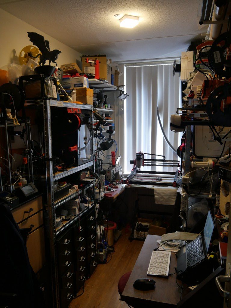
My mini shop


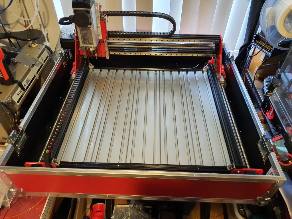
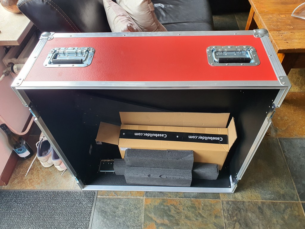
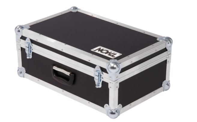
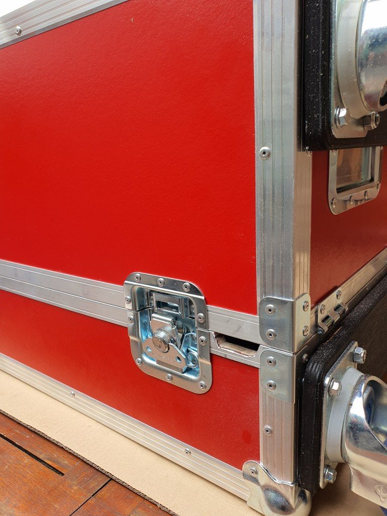
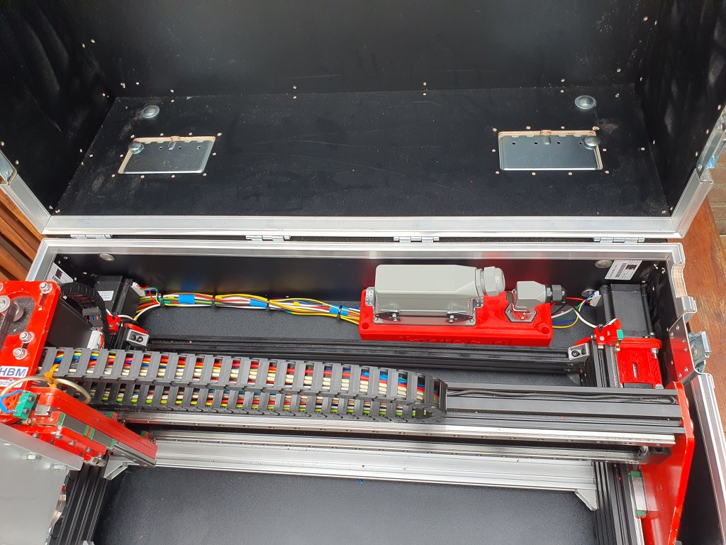
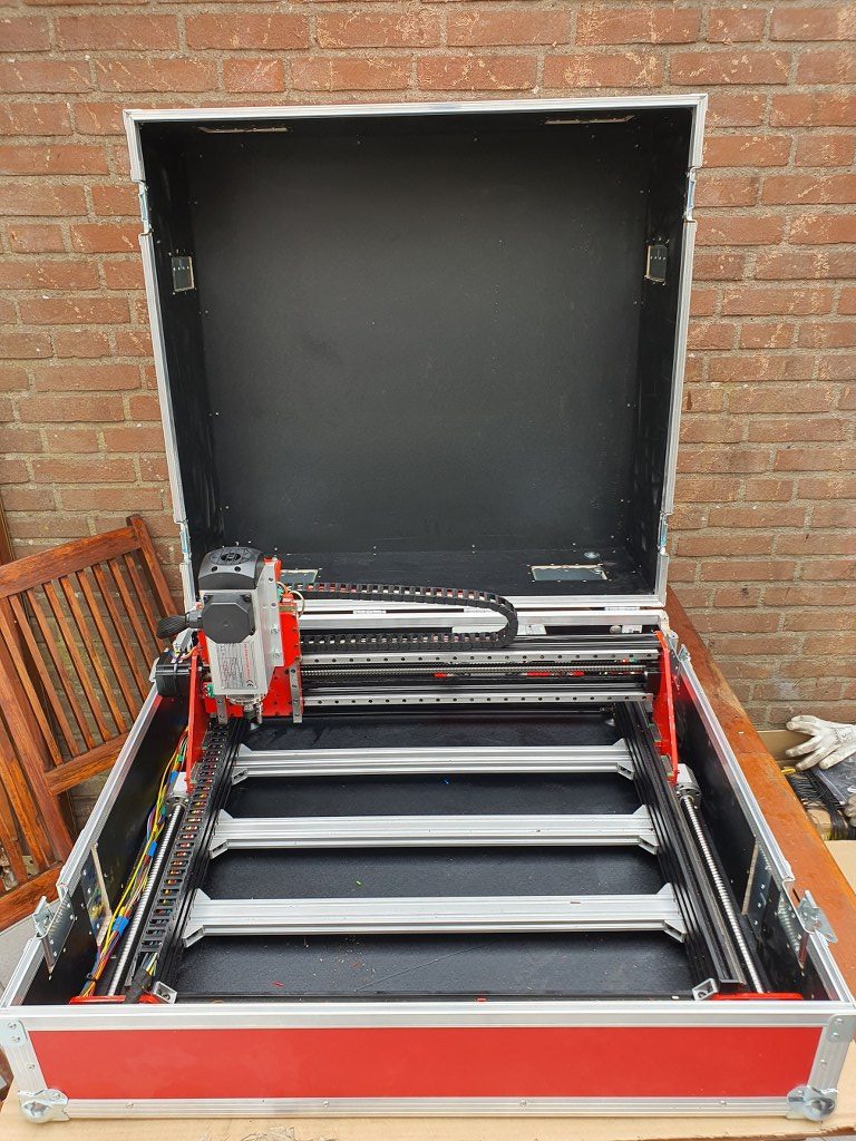
This is only the lower part of the newly built flightcase for the Indymill. It is 15cm high, 75 cm deep and 80 cm wide, all measured on the inside.
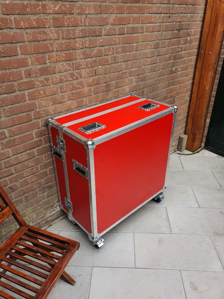
The top of the case is 22 cm high on the inside and it will get perspex windows at the front and top. Wheels will get mounted at the rear so the case can be moved standing upright.
The Indymill will be mounted in rubbers underneath and on the sides of the frame. The connectors to the electronics will be mounted in flightcase shells at the front. When all is positioned correctly and connected, the Indymill will be placed in my garage where I will use it in my large(r) shop.
With the 1.5 Kw spindle I intend to mill aluminium and brass, but mainly aluminium.
1st Job will be to machine ‘flat’ the 8mm aluminium plate I have bought some time ago for the heated bed of my Voron 3d printer. The plate is 310x310mm wide and was not entirely flat when I received it, due to the way it was stamped instead of saw’d. Now, I will be able to get it done right. I will use the boring head from my other mill to get this done. My other mill can only work with smaller objects, not anything as large like the Indymill can handle.
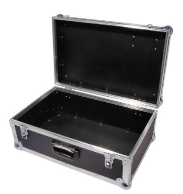
Just ordered me a new case for the Indymill’s electronics from Thomann.de.
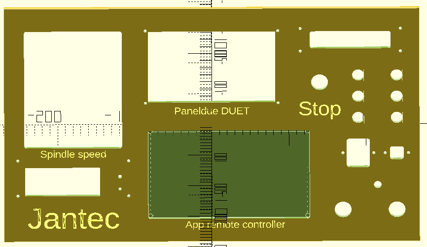
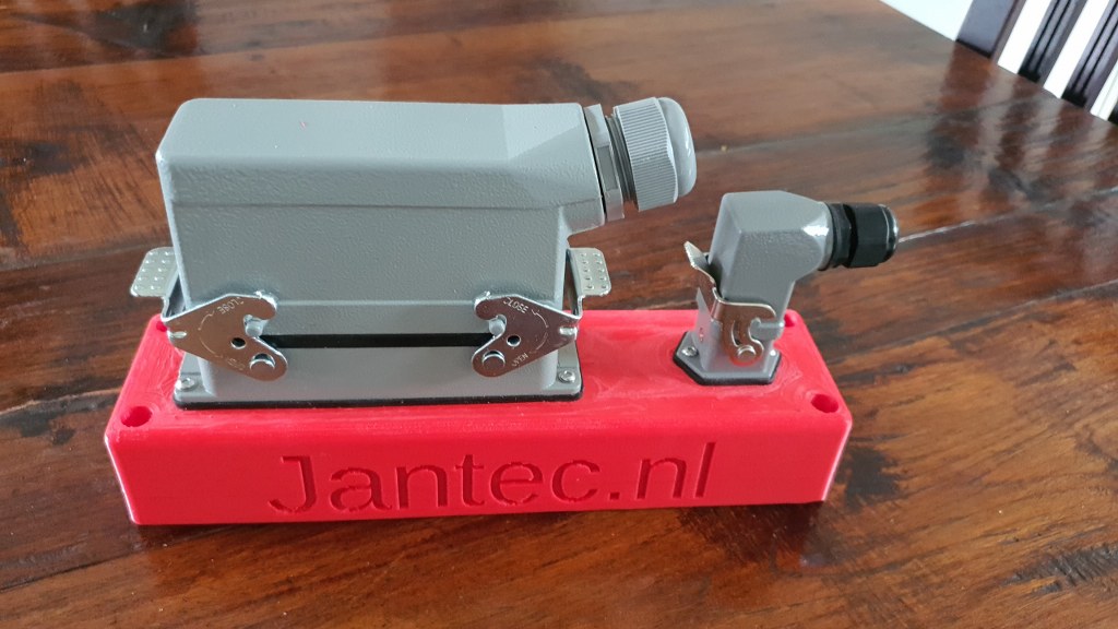
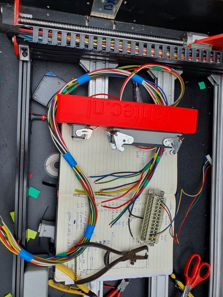
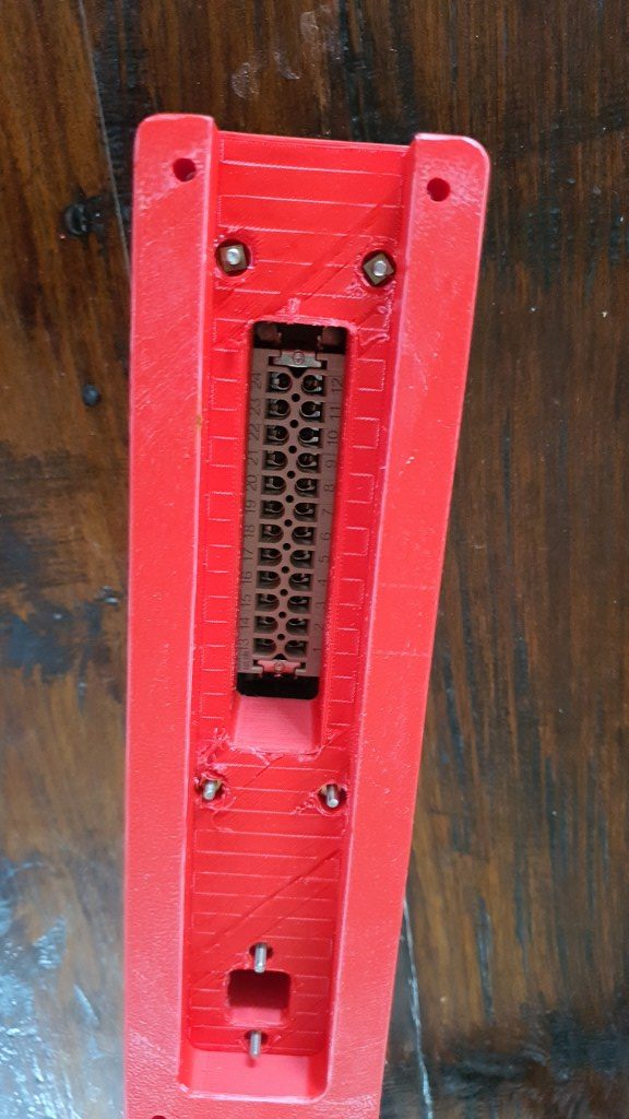
The idea is to get everything mounted in the cases, and use the control case with the lid open. The control case gets connected to the Indymill case with multicables and – connectors. When not used, the cables get disconnected from the Indymill and from the control case and go in the Indymill’s case. The electronics controls will be mounted in the lower part of the control case and the connectors are placed on top of the control panel that gets mounted flush with the top rails of the bottom part of the controller’s flighcase. When closed, everything is neatly stored and can be transported damage-free.
I intend to store the controller case inside the Indymill case, but when moving it around the controller case will be separated from the Indymill case to prevent any possible damage to the mill.
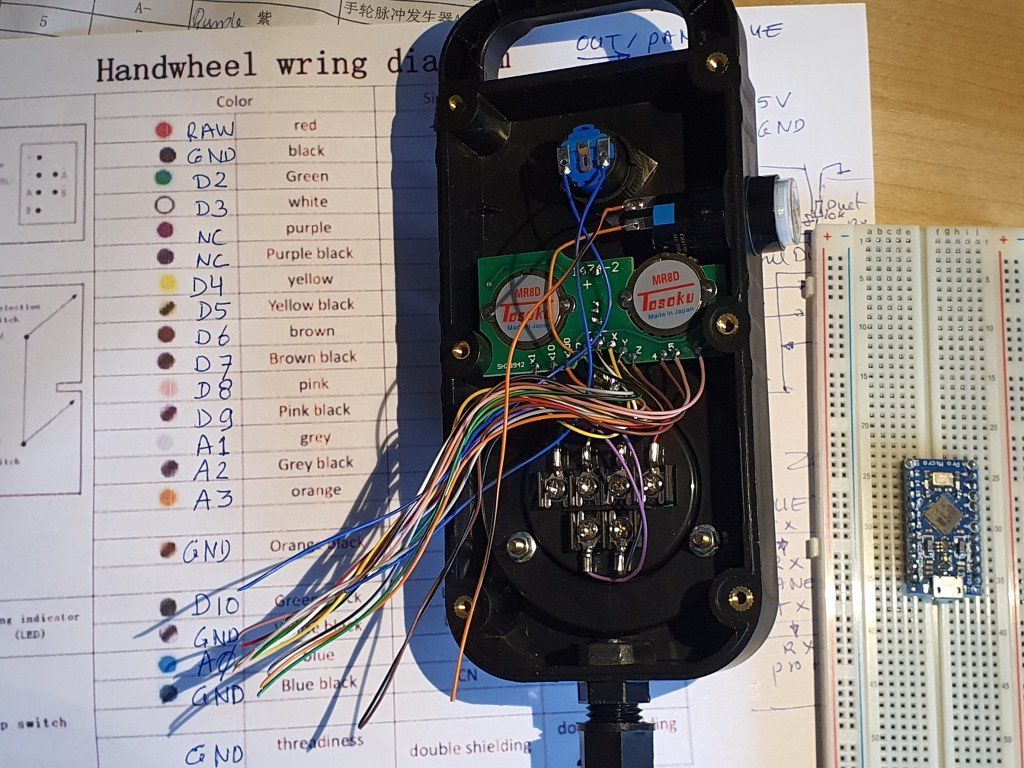
On the Duet support site a very good description and software for rebuilding a Chinese CNC-pendant for the Duet2wifi is available.
I used this description to program an arduino pro micro, and connect it to the pendant wired, place it inside the pendant and connected the pendant with 4 wires to the Duet. This works very well.
In the process, I developed some schematics that may be useful to you, available in this post:
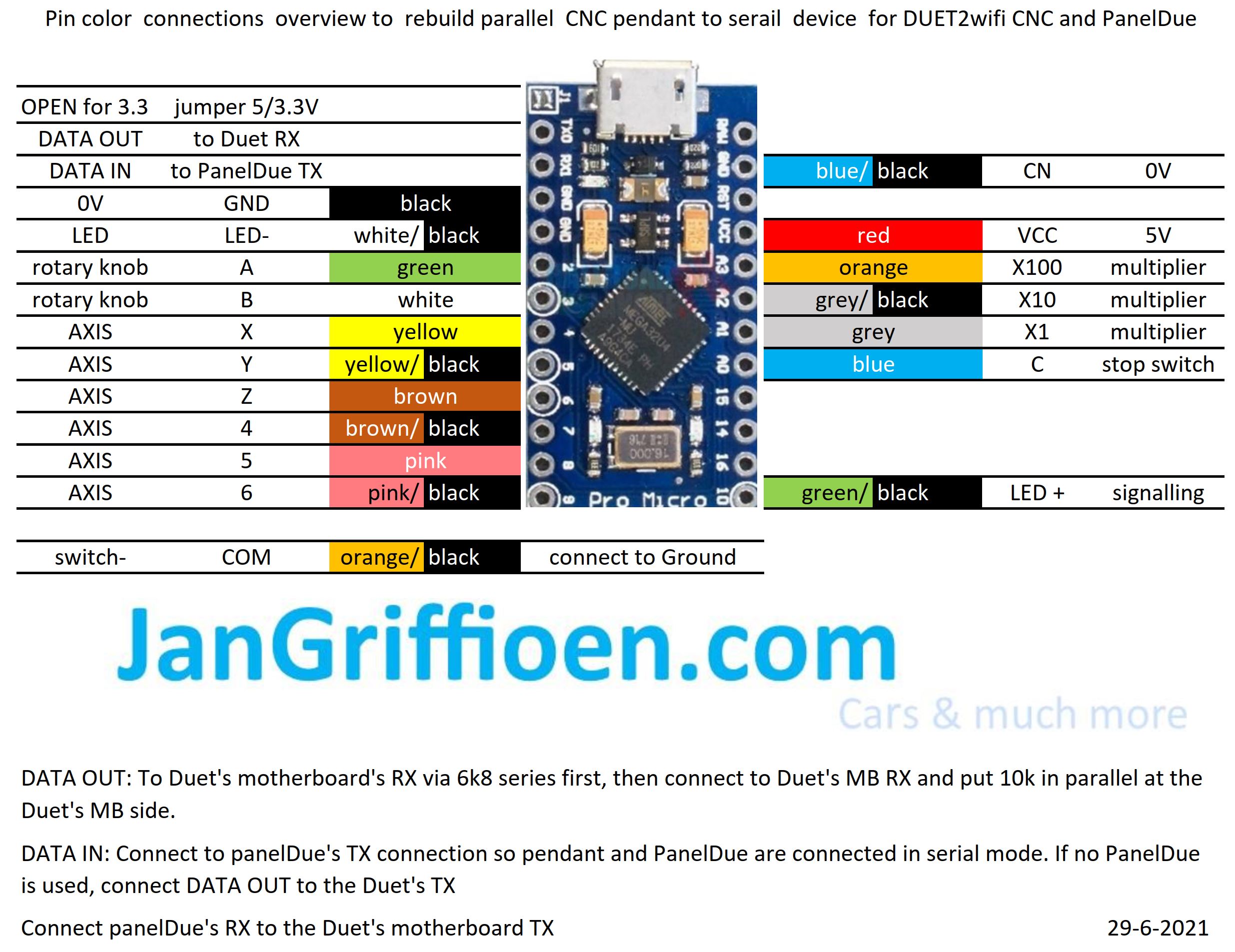
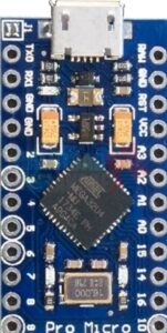
Needed: an arduino pro micro and a pendant like this:

To get the Indymill running, at first I chose to use the Duet2wifi and reprap3 as base.
Since I am very familiar with Reprap and with the Duet, I want to try this anyway.
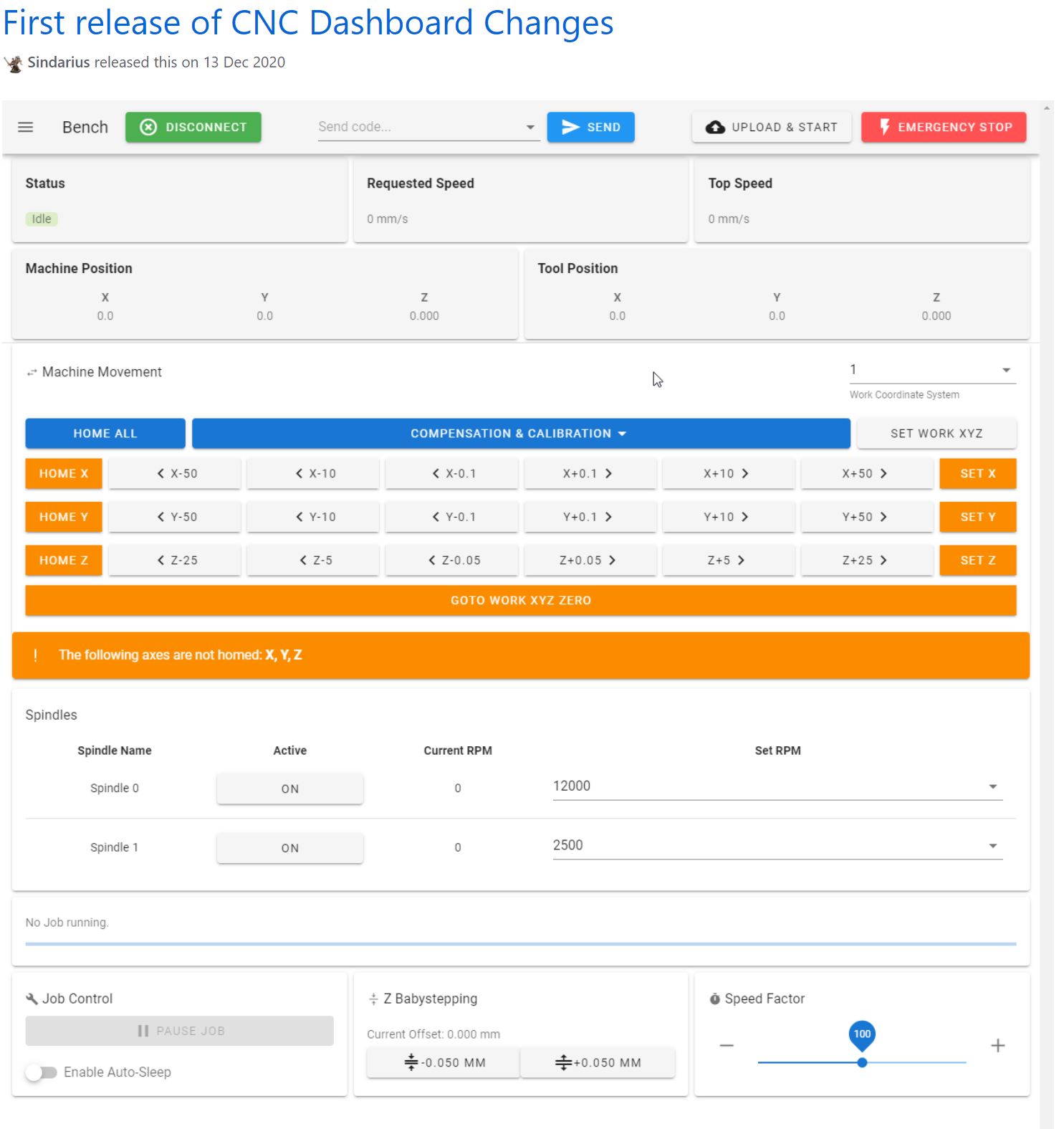
In the end, if it is all installed I need to have software to design and get a file with Gcode and this will be sent to the Duet2wifi controller via wifi, using the Duet’s webinterface that is been developed for CNC in Beta (DWC for CNC).
I currently use Openscad for designing, export as .STL and then make a .nc file for the CNC machine from this with Estlcam.
In Estlcam you can make the machine-specific settings like where the center is, how to set Z=0 et cetera.
The Duet2wifi is my favourite solution because I can if so desired use sensorless homing on any axis. And- because I need to home 2 independant Y axis and I have a lot of experience in making this work I first went for this solution. For my settings with sensorless homing please see THIS POST
When you get a good enclosure for the Duet2wifi, use 24 Volt PSU and good driver cooling blocks, you can push the Amps to over 2 Amp continuously. Works well with my Nema23 steppers. 2.5 Amps is max but we don’t want that, I found that 1.8 Amps works very well and creates enough torque for the Indymill.
After having the Indymill work with sensorless homing I rebuilt all to be used with endstops instead for better stability and compatibility with my other driver board setups. I do want to use the Indymill with several driver setups, and for this setup to be exchangeable, I need the endstops anyhow.
I am currently using reprap boards from Mellow, since they use the raprap firmware that is ported to the STM core that the Mellow boards use.
On top of this, on the esp you can mount the Duet’s DWC software and thus also the DWC CNC software.
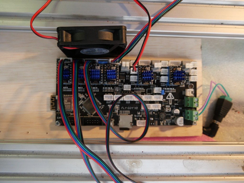
I have this currently running on the Indymill with a FLY-CDY V2 board and TMC2209 drivers.
The nice thing about these Chinese boards is, that you can mount any driver you like, and this means that external drivers is also possible.
So, also the external add-on drivers that do closed loop control can be used. < I was thinking to make this my additional project: Try to do sensorless homing on the Y axes with this, use very low power and switch off the Closed loop during homing.. If I can get this to work, you will read all about it!>
For the Duet, a setup is available on the Duet website to use an original pendant handwheel unit and add an arduino Pro micro to make a serial interface for connecting to the Duet! That is a very welcome addition. See this post!
In the next part of this post my current config file with endstops for Duet/reprap/FLY is shown, as this is operaional for the Indymill.
BE AWARE to use the most current DEVELOPMENT firmware versions for a) the board’s initial firmware, b) the DWC firmware and c) the wifi esp program!
; Configuration file for Board: fly_cdyv2 (STMWiFi)
; Firmware: RepRapFirmware for STM32F4 based Boards 3.3beta1_3 (2021-03-08)
; Duet WiFi Server Version: 1.25-01S-D
; DWC from Sidarius, specificlly redesigned for use with CNC 3-axis
; customized by Jan Griffioen sales@jmwg.nl 2021 04 08
; Made for a CNC Cartesian printer with single X,double Y and single Z steppers and a single spindle with external driver.
; General preferences —————————————————————————————————————-
M453 ; CNC Mode
G90 ; send absolute coordinates
M83 ; and relative extruder moves
M550 PDUET_CNC ; set printer name
M551 Preprap ; Machine password
M552 S1 ; WIFI ON
; Network —————————————————————————————————————————-
M586 P0 S1 ; enable HTTP
M586 P1 S0 ; disable FTP
M586 P2 S0 ; disable Telnet
M552 P0.0.0.0 ; IP address (0.0.0.0 = use DHCP)
M554 P192.168.178.1 ; Gateway
M553 P255.255.255.0 ; Netmask
M555 P2 ; Set output to look like Marlin
M575 P1 S1 B57600 ; comms settings S1 for Original PanelDue and Fysetc 7 inch TFT =OK
; Drives —————————————————————————————————————————-
M569 P0 S1 D2 ; physical drive 0 goes forwards using default driver timings
M569 P1 S1 D2 ; physical drive 1 goes forwards using default driver timings
M569 P2 S1 D2 ; physical drive 2 goes forwards using default driver timings
M569 P3 S1 D2 ; physical drive 3 goes forwards using default driver timings
M584 X0 Y1:2 Z3 ; set drive mapping
M350 X16 Y16:16 Z16 I1 ; configure microstepping with interpolation
M92 X640 Y640:640 Z1600 ; set steps per mm
M566 X500 Y500 Z300 ; Set maximum instantaneous speed changes (mm/min)
M203 X2700 Y1400 Z1000 ; Set maximum speeds (mm/min)
M201 X300 Y300 Z150 ; Set accelerations (mm/s^2)
M906 X1800 Y1800 Z1800 I30 ; set motor currents (mA) and motor idle factor in per cent
M84 S100 ; Set idle timeout
; Axis Limits ————————————————————————————————————————-
M208 X0 Y0 Z0 S1 ; set axis minima
M208 X500 Y480 Z100 S0 ; set axis maxima
; Endstops —————————————————————————————————————————-
M574 X1 S1 P”^xmin” ; configure active-high endstop for low end = LEFT on X via pin xmin
M574 Y1 S1 P”^ymin+^ymax” ; configure active-high endstop for low end = REAR on Y1 and Y2 via pin ymin and ymax
M574 Z2 S1 P”^zmax” ; configure active-high endstop for high end = TOP on Z via pin zmax
; Z-Probe ——————————————————————————————————————————
; a probe must be defined here to have a Z=0 DATUM, including the offset (when there is any, If you use the tip of the tool no offset is required. OR, use manual Z-datum setting via a dedicated macro!
; Mesh G29 —————————————————————————————————————-
;M557 X15:215 Y15:195 S20 ; define mesh grid to be called upon by G29 for an authentic Mesh bed levelling IF this is required and possible
; Fans ———————————————————————————————————————————–
M950 F0 C”fan0″ Q500 ; create fan 0 on pin fan0 and set its frequency
M106 P0 S0.5 H-1 ; set fan 0 value. Thermostatic control is turned off
; Tool definition section; —————————————————————————————————————-
M950 R0 C”!e2heat” L25000 ; Create spindle index 0, with PWM pin on heater 2 output and 25000 RPM achieved at full PWM. At this port, add a PWM-> Voltage 1-10V converter!
M563 P1 S”Spindle 1″ R0 ; Create tool 1 with spindle 0 and call it “Spindle 1”
; Miscellaneous —————————————————————————————————————————-
M140 H-1 ; Disable heated bed
M564 S1 H1 ; Disable jog commands when not homed
M98 P”customconfig.g” ; Execute custom config settings
; Epilogue ———————————————————————————————————————————
;M556 S78 X0 Y0 Z0 ; Axis compensation here if needed
;m98 P/sys/leds_show.g ; Neopixels show (max number is 60)
;m98 P/sys/leds_off.g ; Neopixels OFF (max number is 60)
T0 : select first Tool
M501 ; execute config_override.g
After configuring the reprap Mellow FLY-CDY-V2 motherboard for CNC including the webinterface and installing Mellow’s TMC2209 driver units I got sensorless homing setup for the Indymill.
It took a lot of time to get it all tuned, as the 3 axes act entirely different due to their different inertia. The weight that is carried is obviously higher for the Y- than for the X axis. And the 4 kilogram weighing spindle engine made it pretty difficult to get the Z axis tuned.
The resulting config file is provided in this post. Use this with caution, since every machine is different, and the used stepper motors, cabling, steppers and PSU all have influence on the CNC’s behaviour and thus on the config settings.
To have the original Mellow FLY TMC2209 drivers work with sensorless homing, set the underneath dip switch to ON

(Diag pin will then be connected). It took me some time to find out that this is different than other TMC2209 drivers, where the Diag pin is activated by jumper settings on the motherboard. No idea what happens when you use non-Fly TMC2209’s on the Fly board, but I expect this will not work for sensorless homing.
What I experience on the Y axis is that if you have real problems with homing or skipping steps, the steel Y carriage plates may bend and cause a non-square Y carriage that will never align any more. I repaired this but preventing is better.
GO TO THE INDYMILL & Reprap Driver POST
Since this setup with sensorless homing never gave me good speed ratings, I disassembled this setup and continued with endstop setup. If you want to know how to setup sensorless homing with reprap, please look at my sensorless homing setup on my dual carriage 3d printer, where this works perfect!
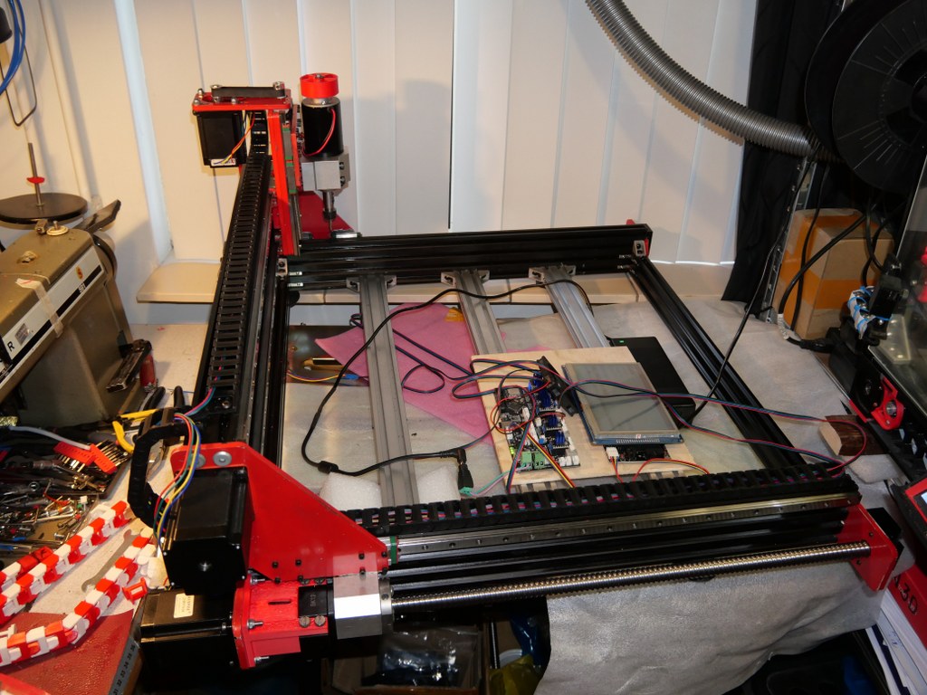
This is my test setup for a 1.4 RAMPS shield on top of an Arduino Mega with TMC2209 drivers, optical endstops and individually homing of dual Yaxes PLUS an LCD that shows the exact XYZ locations anytime.
Firstly, I must admit that this option was initially NOT on my list bacause I felt this was a pure hobby-like option. BUT- as my requirements list grew and other options got less and less, I ordered a Ramps 1.6 shield and plugged one of my Mega2560 boards under it. Then- the search began to get a working fork of GRBL for arduino that both accomodated the Mega 2560 and my requirements list. On this list: GRBL, Squaring my gantry, LCD with useful data, Handwheel connection, Preconfigurable buttons on the handwheel (stop, define as zero, probe here, et cetera). The fork that does this all is: GRBL-Mega-edge. The last comment is of April, 2020 and the fork was updated last in 2019. But- it works straight out of the box and the documentation is very well maintained.
Since it works under the Arduino IDE and has its own library, I foresee little problems in the future. Everything is freely configurable and it might even be possible to put an Arduino Due in place of the Mega2560 in this setup, with some tweaking of pins and speeds. And- tweaking is required for the hardware as well. The Ramps boards were never designed for 24 Volts, so this needs to be taken care of. One might of course use 12 Volts and use external driver modules, but I intend to keep everything very small and make use of an external PSU, and a small handwheel-like box for the Mega2560, Ramps, drivers, LCD, buttons and handwheel knob. By the way: For getting my designs I already had from my 3d printer background towards the CNC I bought Estlcam (CAM program). This really does a great job at converting it to Gcode and sending it to my Grbl- Mega 2560/RAMPS setup.
Afterthoughts 2021-06-22: When connecting Estlcam to the Mega2560 and RAMPS1.6 shield, Estlcam can program the RAMPS / Mega2560 configuration, including dual X and Y axis. This works straight out of the box including endstops. Actually this is easier than first compiling GRBL on RAMPS with Arduino’s compiler. BUT- it seems that autosquaring does either not work or I did not install Estlcam’s options correctly since the endstops on the dual axis appear to function in parallel instead of indicvidually per axle.
24 Volts connecting is not possible on a RAMPS shield just like that. I removed D1 and powered the Mega2560 with a 9 Volts PSU, and the shield seperately with 24 Volts. For the Arduino DUE, dedicated RAMPS boards are already available (Smart ramps that compensates for the 3.3 volts in/out Voltage of the Arduino Due)!.
Another option for Estlcam is to program the Mega2560 without RAMPS shield and connect everything directly to the Mega2560 with jumpers. If this is done, Estlcam will do the bare programming of the Mega and Estlcam can steer almost everything. Since I bought a license for Estlcam I will, at a later stage, try this as well. SEE THIS POST
My main supplier of parts is Aliexpress, and I also buy a lot from Banggood.
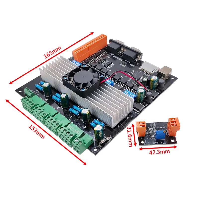
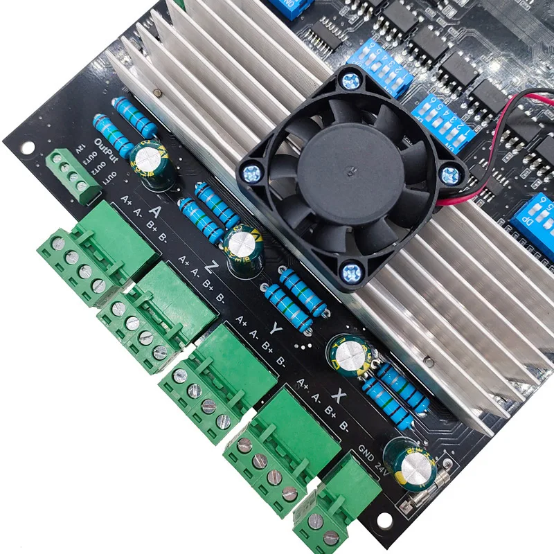
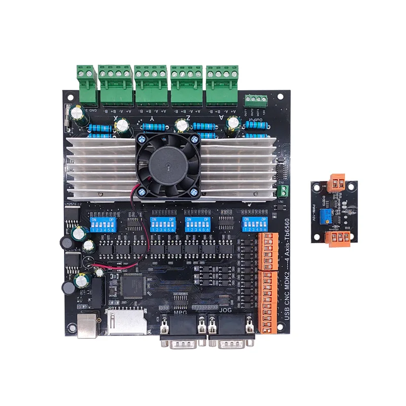
At Aliexpress, I recently discovered a board that will interact with Mach3 and has onboard drivers for larger stepper motors like Nema23.
This board takes 24 Volts, has a USB connection to the PC, an SD card slot and 2 x MPEG/control connectors 15-pin/3-row.
I ordered me 1 of these boards to test it on my CNC mill:
Usb Cnc MDK2 4 Axis TB6560 Stepper motor Controller with Mpg Interface 100Khz Driver Breakout Board
I have this tested with Nema23, 24 Volts and the accompanying firm- and software.
It was quite some puzzling to get the drivers installed and I discovered I had to switch off the Windows 10 security feauture that prevents unsigned drivers to be installed. You can set this off via a procedure which restarts your PC via a series of keyclicks and restart options in the Windows menu. It can all be found on the Internet. After this, the board worked perfect.
I also bought a handwheel set, which has a male 15 pin VGA connector, as does the board. I ended up ordering me a female-to-female 15 pin VGA unit from Ale, will see if this works.
The other 15-pin connector (also male) can be used for simple switches to direct all axes up/down or forward/backwards. I will use this to make auto toggle swtches directly at the machine, next to the Nema steppers. I have some nice jogging handles that will fit perfect for this.
Also, I bought e a 4th axis unit hat will get connected to this boardon the Minimill.

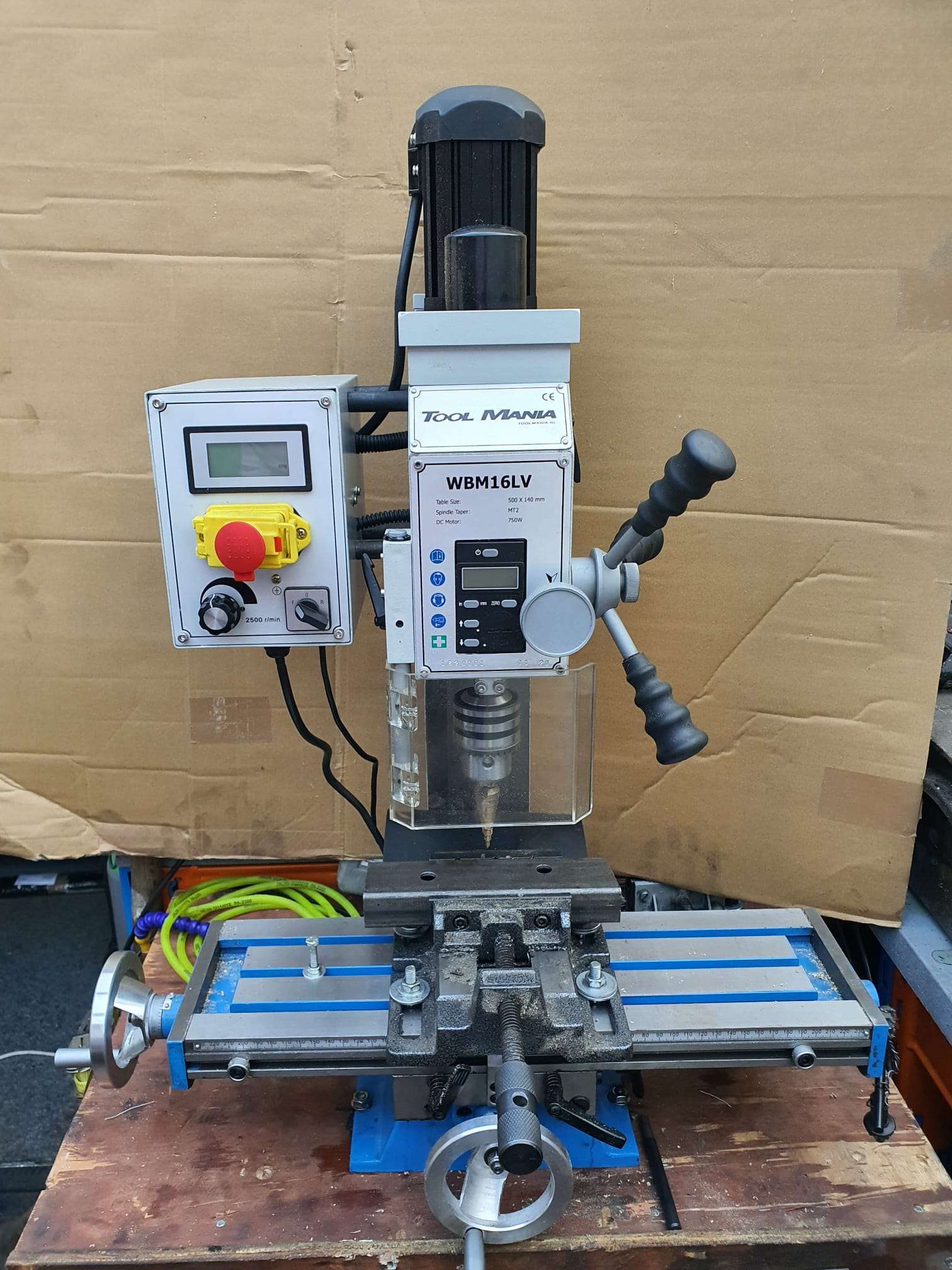
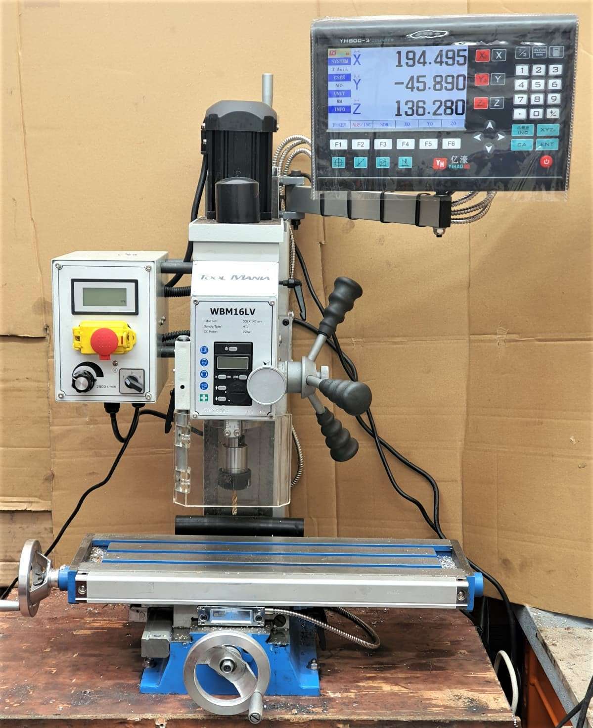
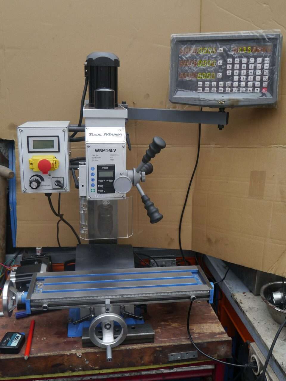
So, after a long search I finally replaced my very old column drill for a small model column mill from Toolmania. I had the last one still available from this series.
The old drill -)
It is a model WBM-16LV with an indirect belt-driven spindle with a 750 watt vario motor. Even at low rpm there is still quite a bit of power on the motor.
This model is actually largely a standard model but with a more powerful motor, with a small LCD for the Z-movement of the 50mm Z-handle and with a wider bed.
The working space with this column router is: X:330mm , Y:140mm and Z:180mm
The spindle has MC2 inclusion with a pull/screw of 10mm. With this, at least a cutter, drill or head will never fall out.
In addition to buying tools, I always notice that you need at least the purchase value of your tools in consumables and additional tools. No different for the mini mill. The glass scales, collets, milling cutters, CNC conversion, gas spring, holders for the table, indexer and so on together cost much more than the cost of purchasing the column cutter.
I immediately replaced the standard 1-16mm rack and pinion drill chuck that came with it with a standard 1-13mm manual-open chuck. But really, I only work with the fixed spindle heads, collets, and the fixed sockets for both milling and drilling.
The associated stuff like an ER-25 collet holder with 15 collets, boring cutter MC2 and so on are from HBM.
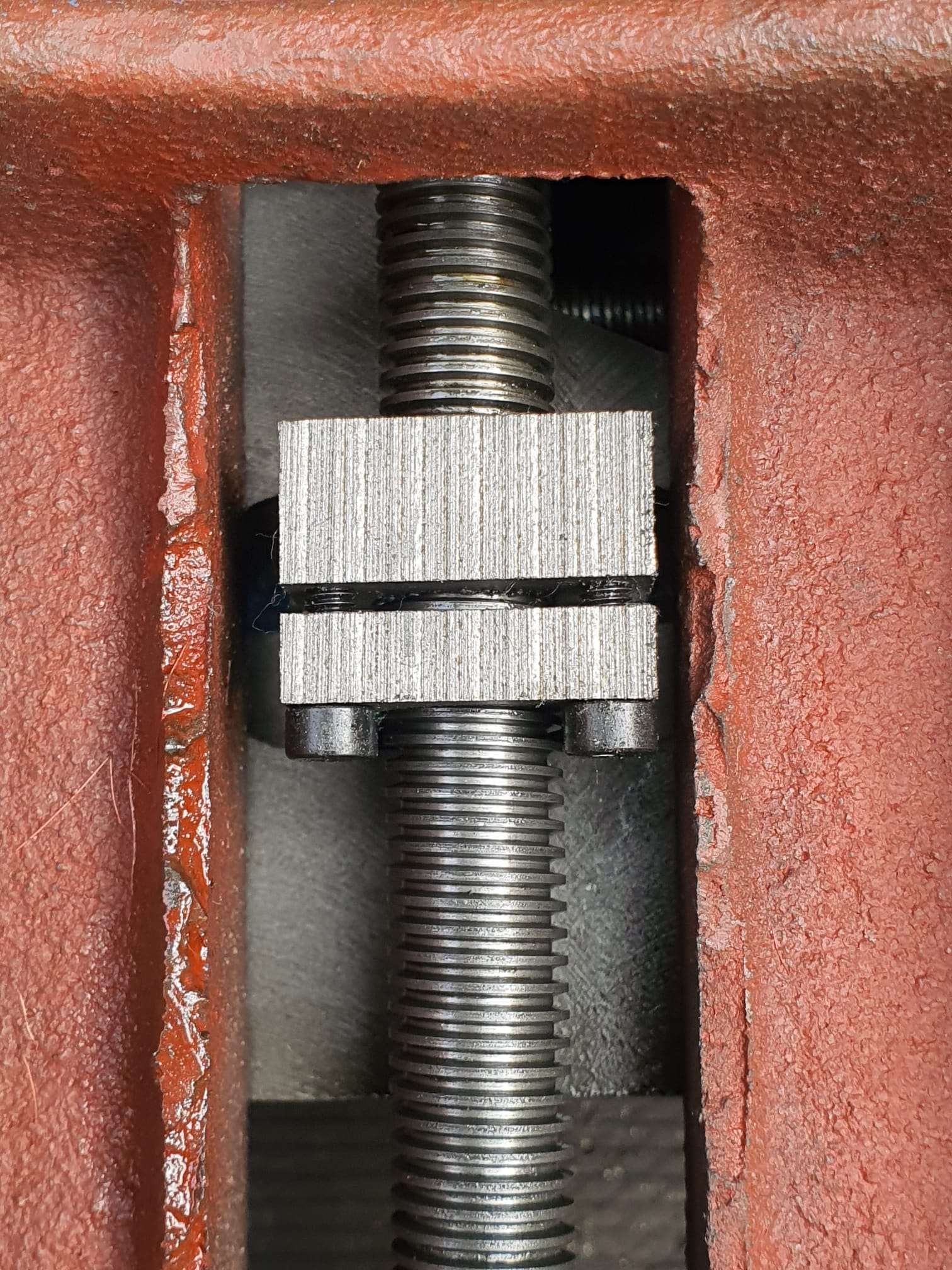
The table has been adjusted for play on the X and Y axes.
The vertical column has also been adjusted for play, and screwed very tightly again.
Besides the conversion to CNC I have mounted 3 glass scales of respectively 170 (1x) and 370 (2x). Because my old display module didn’t work with the ordered glass channels I ordered and mounted a matching new module, this one works with an LCD.
For converting the column router to CNC, I have already prepared everything and ordered all the stuff I don’t have in stock.
The column router will be used mainly for milling keyways and occasionally some milling work on ball bearing housings and the like.
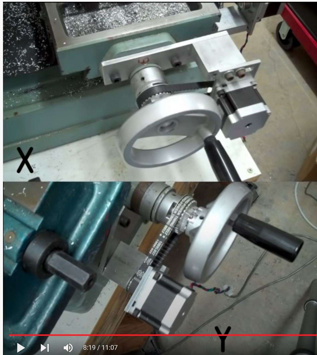
The column cutter will also be used for drilling and occasionally for aluminum milling, and then a CNC setup is useful. The CNC setup will be identical to my Indymill. It will have Nema23 stepper motors with 1:2 belt drive for X and Y and 1:3 drive for the Z axis. I am going to try to merge the handwheels with the gears and then reuse them so that it remains possible to operate manually. The electronics will again be wifi-based with Duet web-based controller and a cloned motherboard from Mellow (FLY) with 2209 stepper drivers.
The limit switches will be inductive: 2 pieces for X, 2 pieces for Y and 1 for Z-top.
The Z-min (or Zero) will be a probe module for the toolbit, which can be put in a fixed place on the table. It would be nice if the column could be electrically isolated from the spindle so you could really do the zero setting on your workpiece. I’m still going to figure that out.
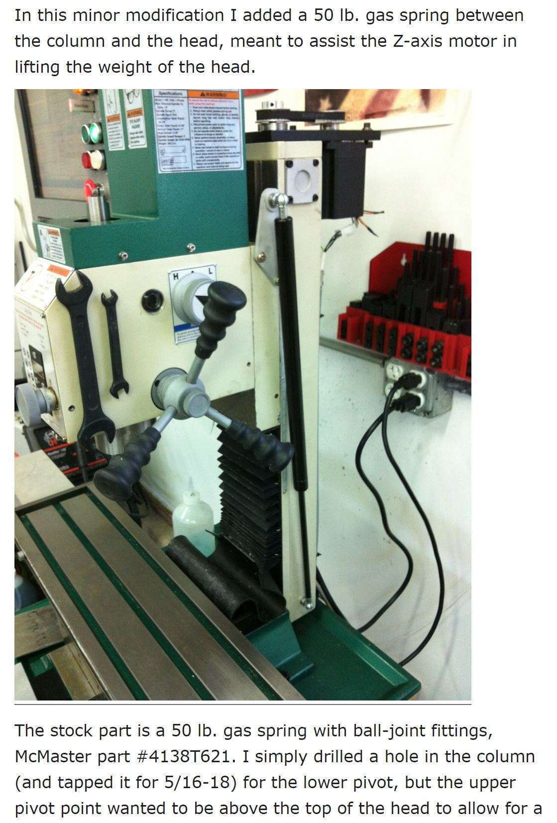
For the Z axis, I ordered a 600mm long gas spring, with an operating stroke of 250 millimeters so the column can move more easily.
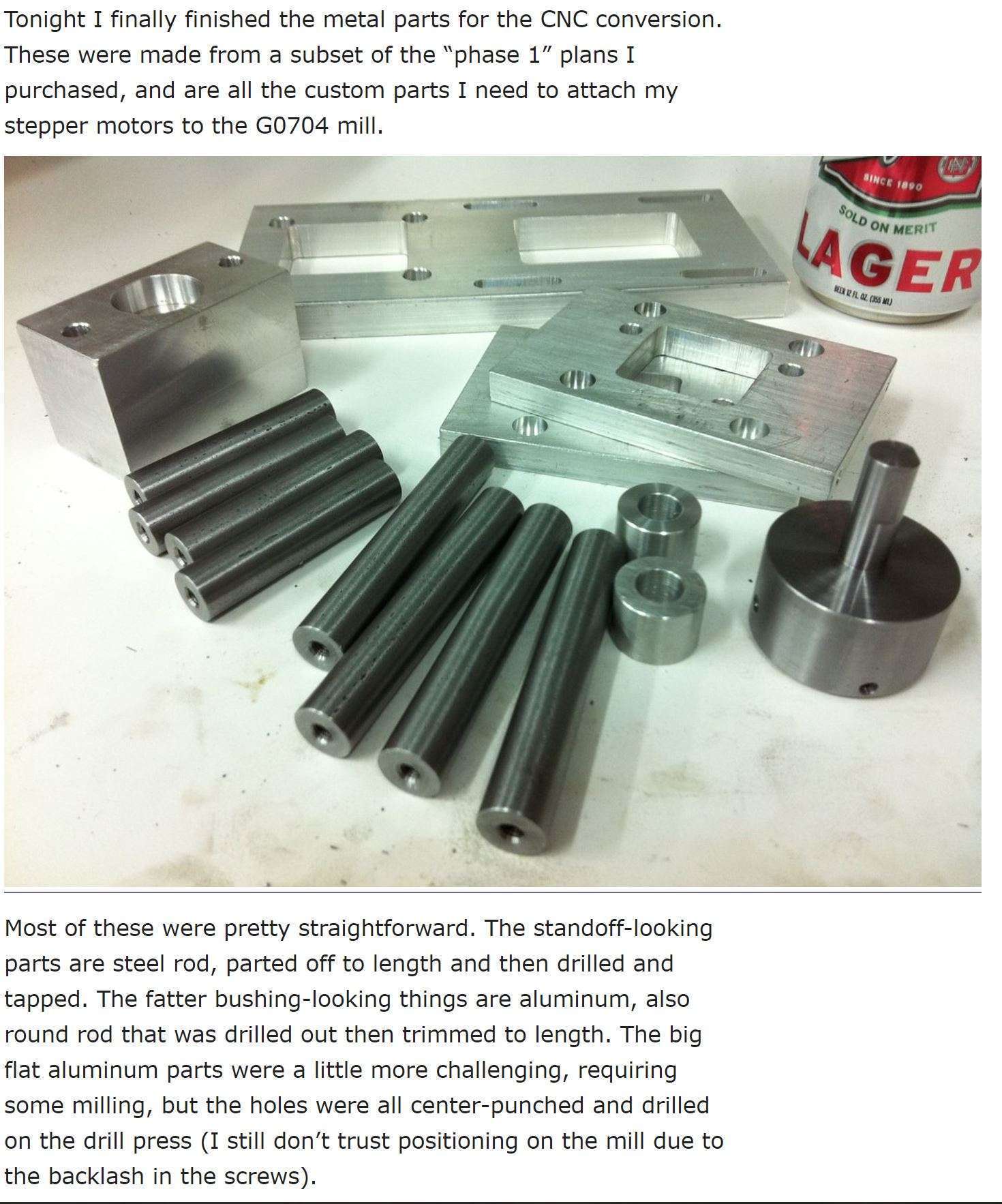
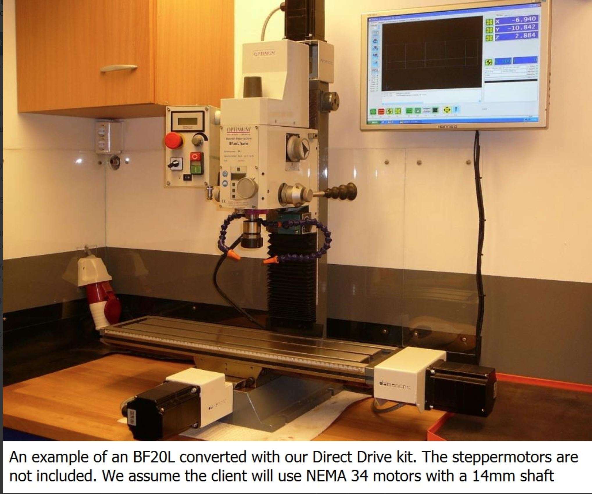
Examples from others for my CNC conversion:
DOWNLOAD ALL MY CNC ADAPTER DESIGNS as STL, .nc and OpenScad!