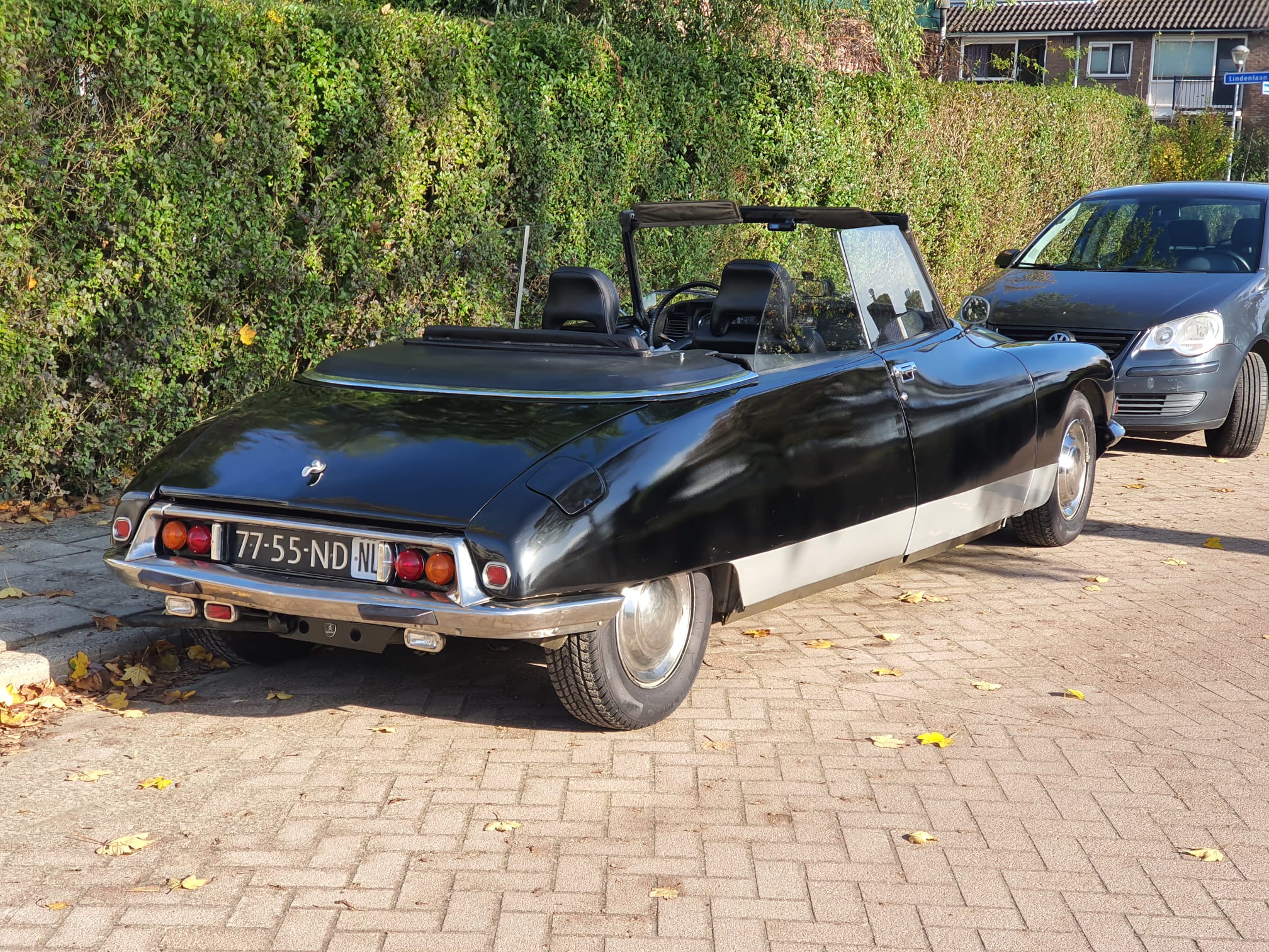
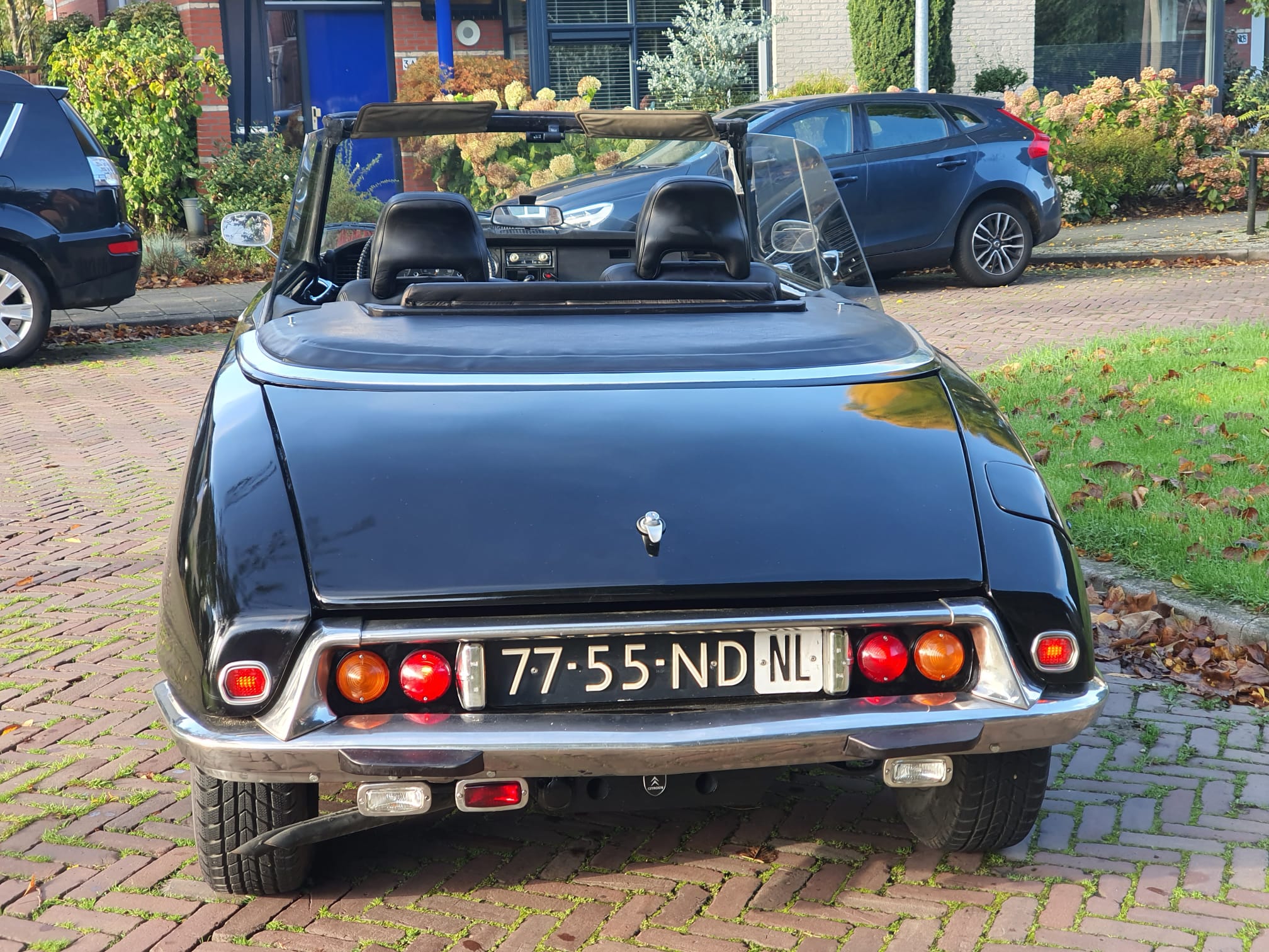
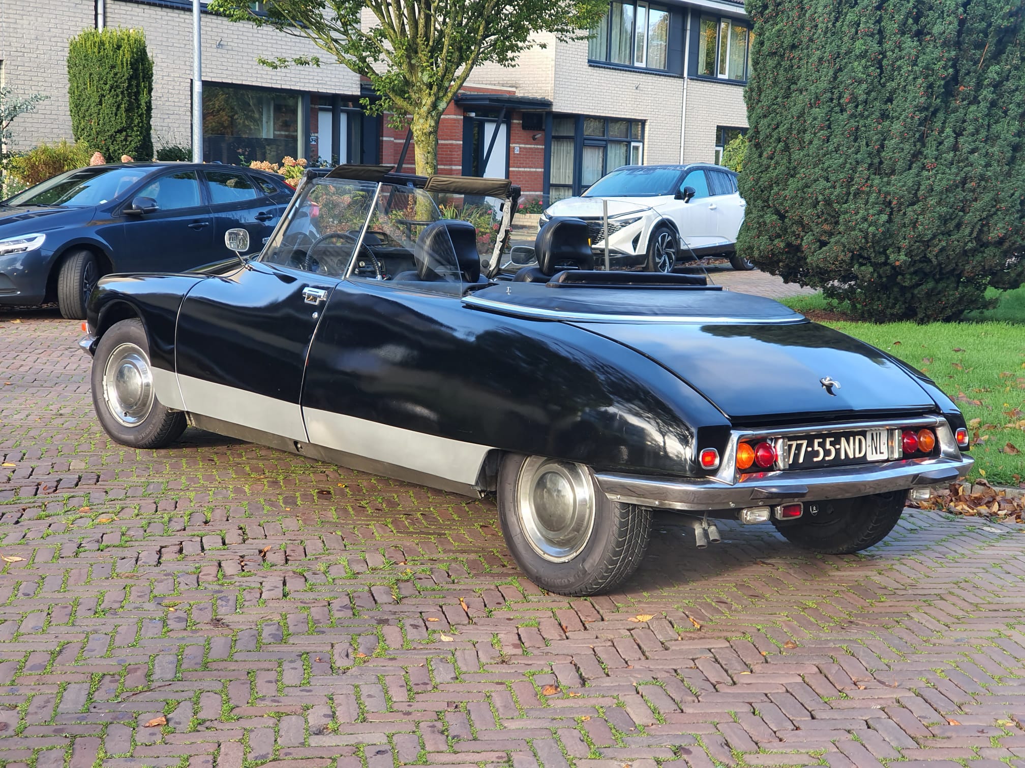
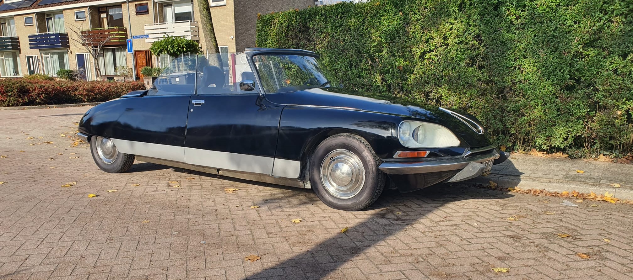
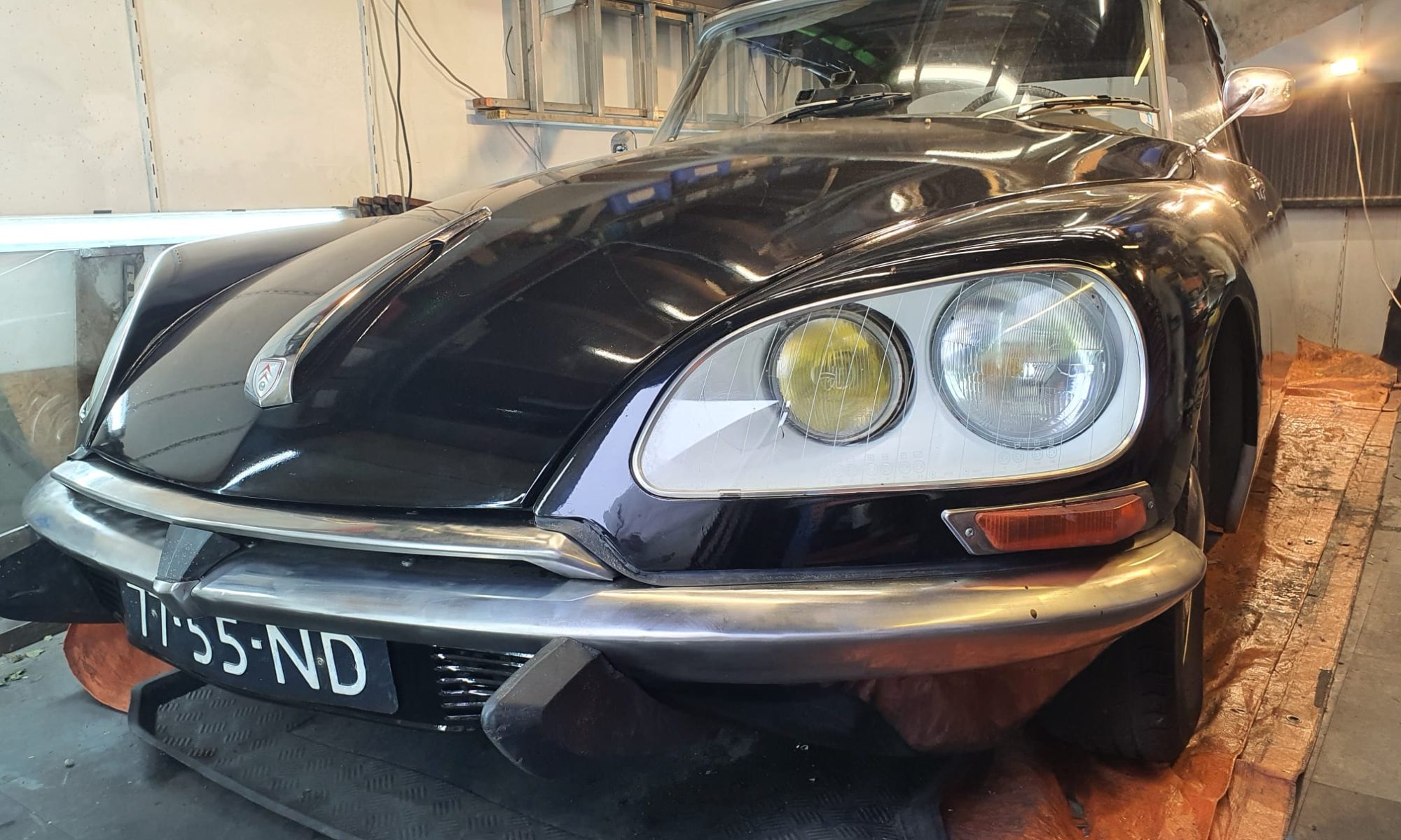
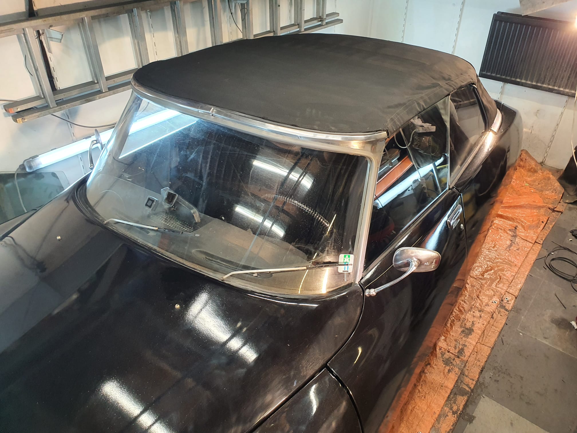
My 1970 Citroën ID20/DSuper5 ‘Oord-rebuild’ convertible is for sale because I need the space for other things I want to do.
Info can be obtained via info@jantec.nl.
The car is in good driving condition and I do not drive it often, max 100-200 km each year for the last 10 years. I find it easier to use my daily driver car which is parked out front. The Citroën ID20 Convertible is a nice car for holidays, weddings and so on.
Although a lot of time and money has been invested in the car, it is by no means an original Citroën ID20 convertible.
The car is nice to drive during summers with the hood down or up. It is not a car that you want to drive in wet conditions, at least we never do.
The car can very well be used in normal traffic conditions, including driving highways due to a.o. the relatively strong engine, power steering, power brakes, 5-speed gearbox and due to the electronic cruise control system.
The car runs well on gas and/or LPG (GPL).
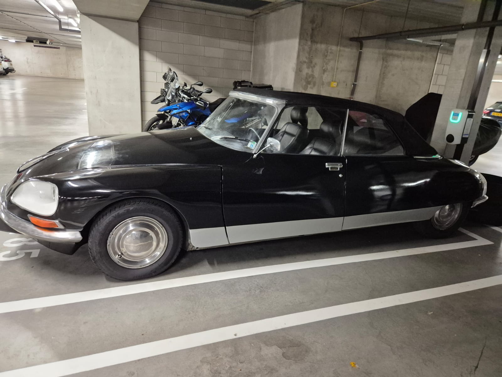
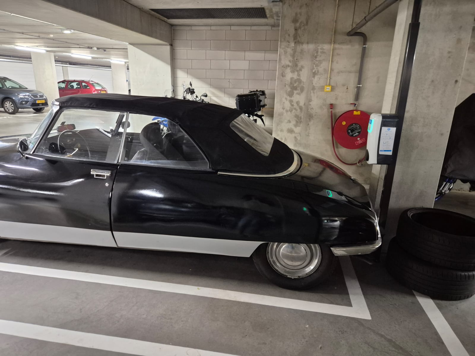
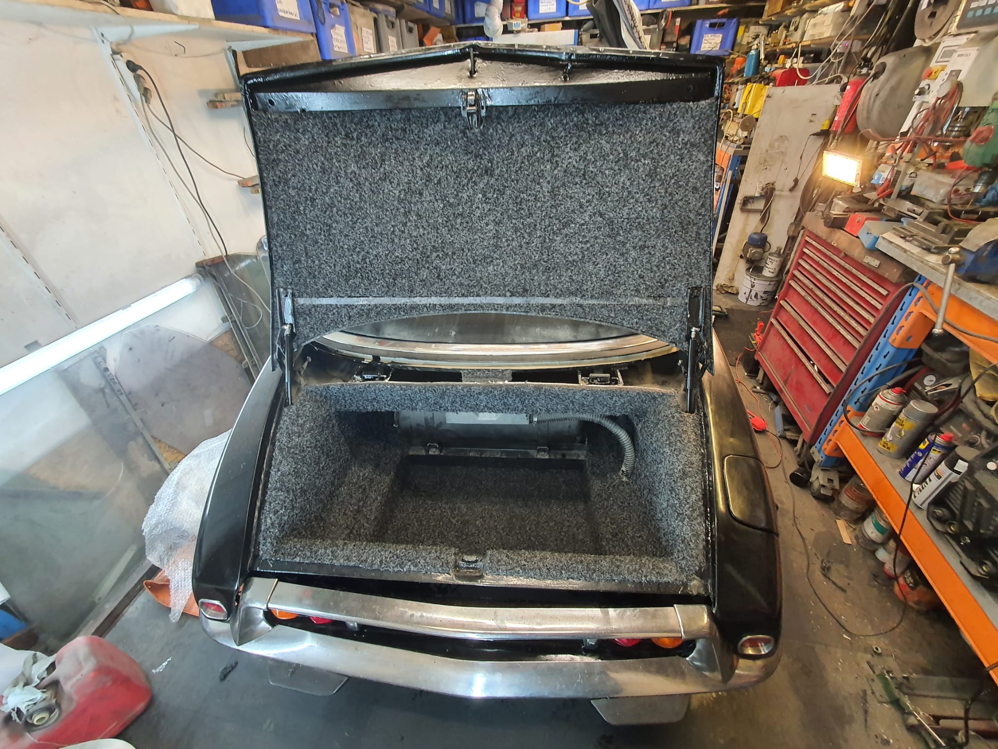
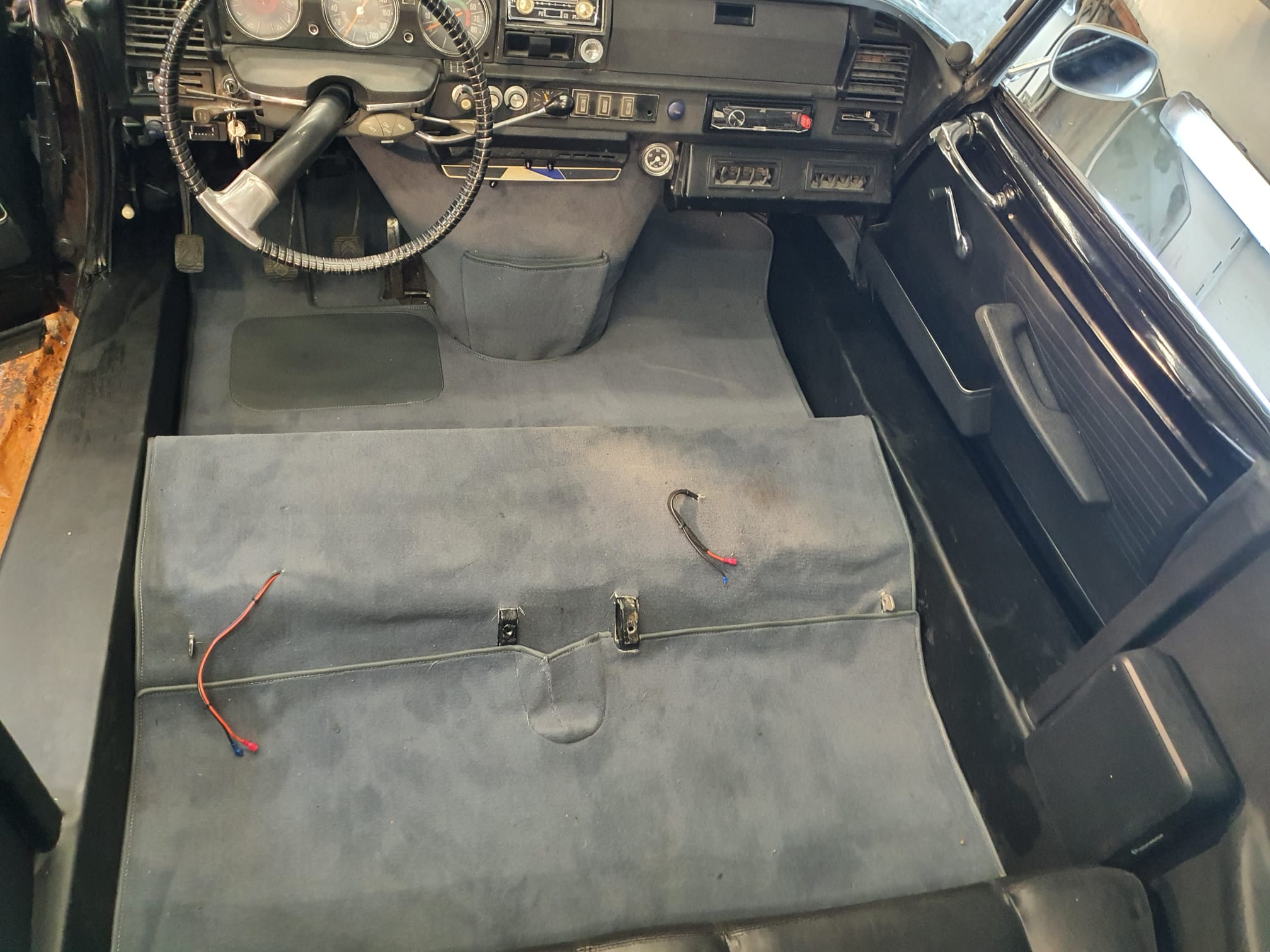
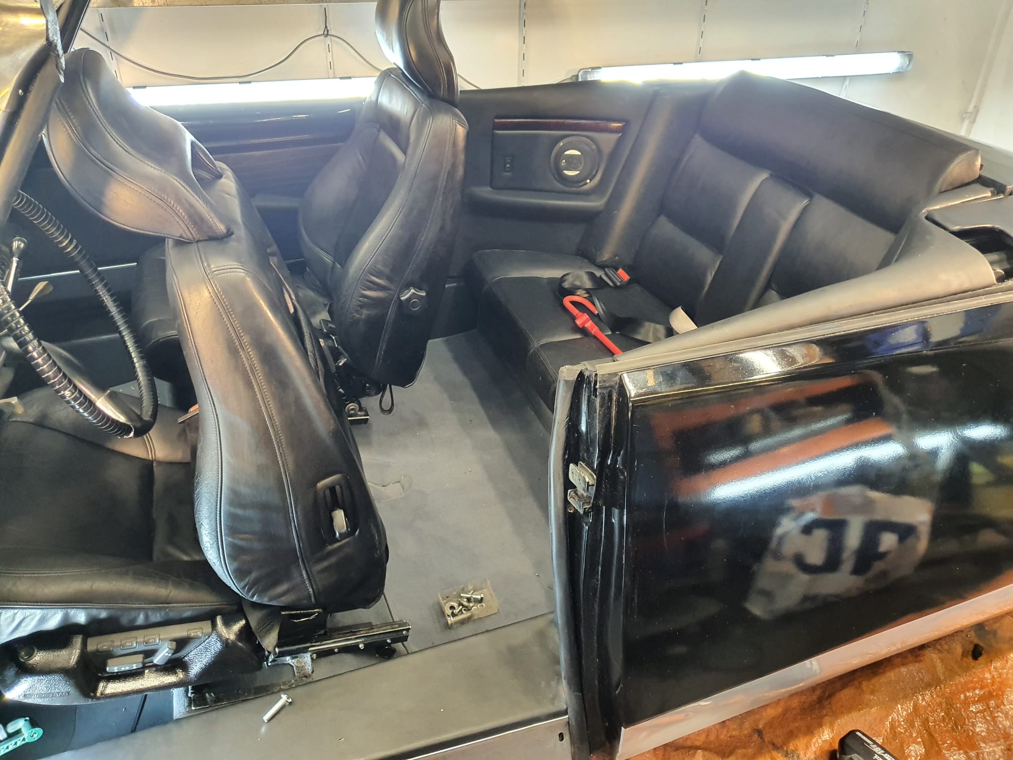
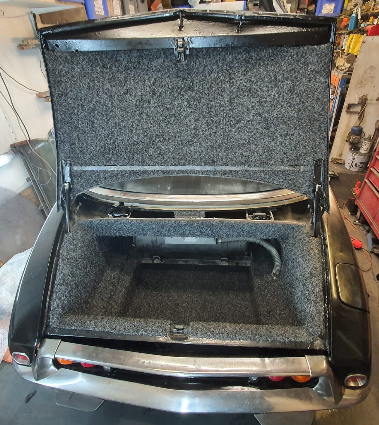
The added pictures are taken on 10-2024 (outside) and 06-2025 (in our Amsterdam garage): the car is always parked inside.
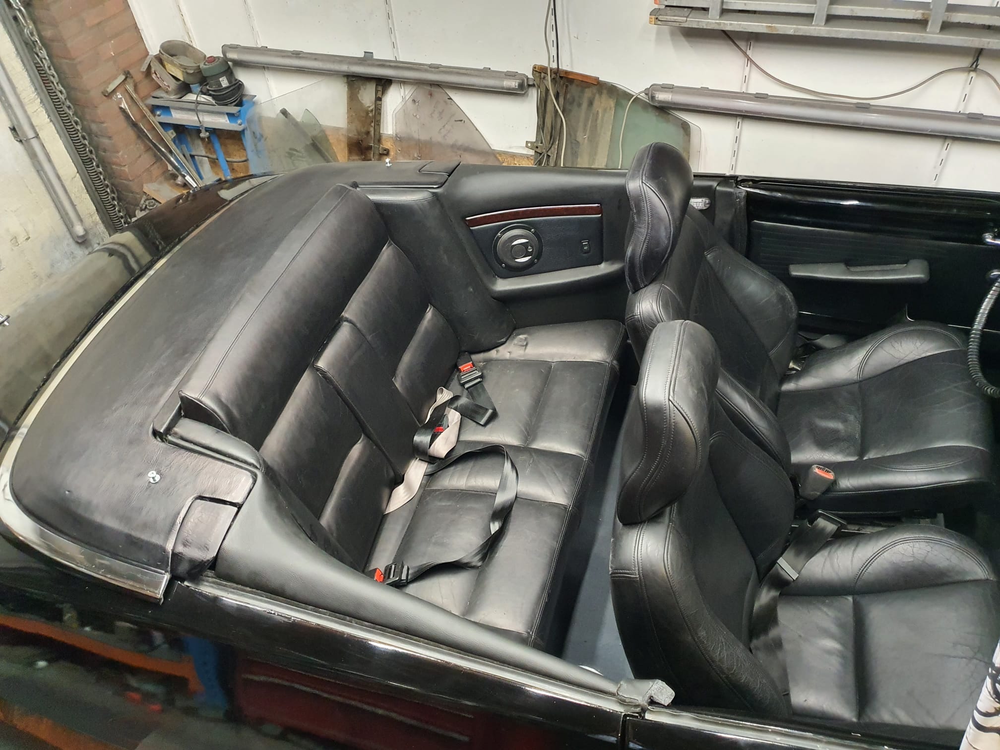
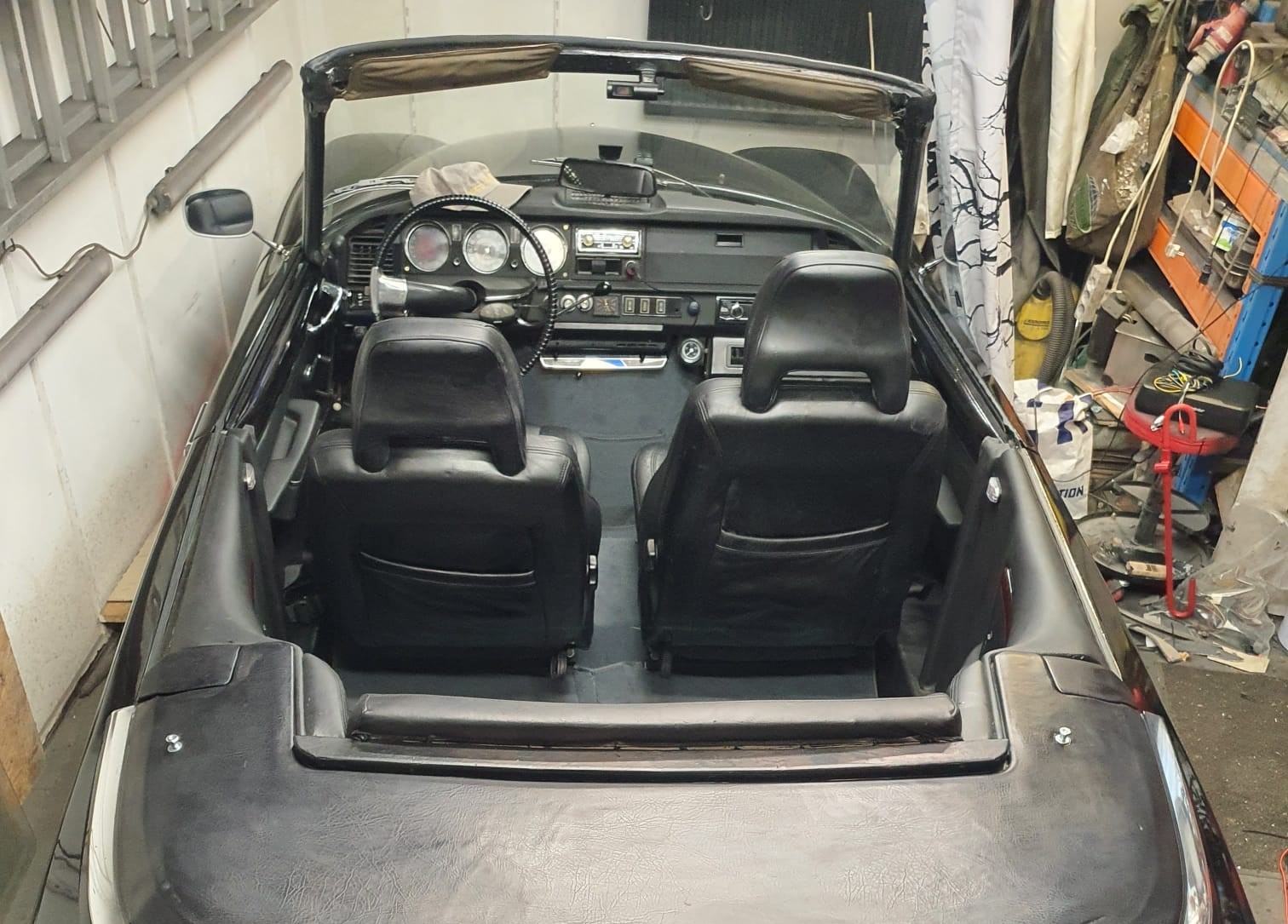
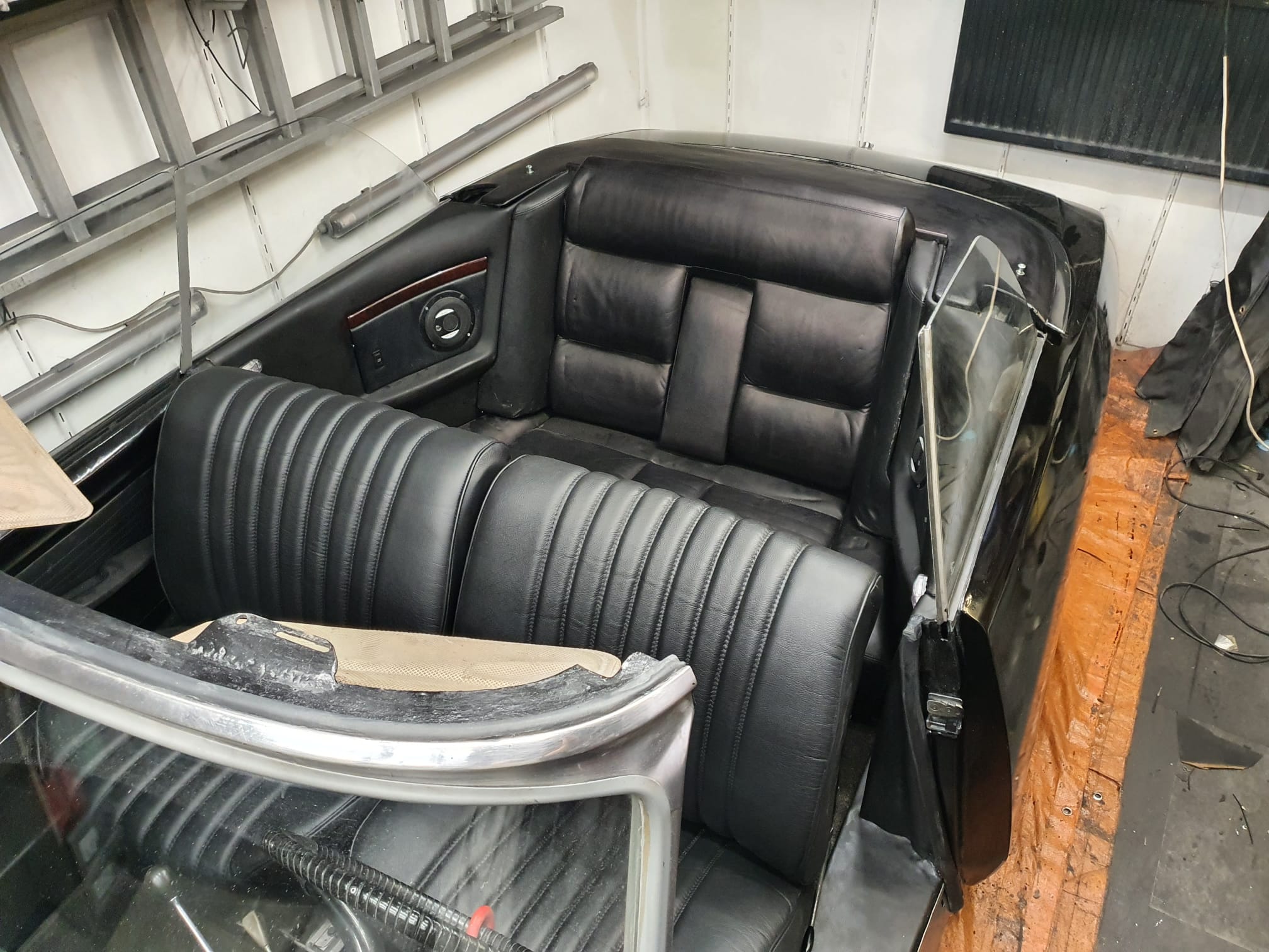
PS: In the photo’s below, my favourite (Volvo C70 cabrio) front chairs were mounted in the car, but I have taken these out due to the sale of the car and remounted the original newly upholstered ID20 chairs. Photo’s with the original leather ID20 chairs are shown further down in this post.
The original ID20 chairs are newly upholstered:
I bought the car as berline in 2006 and drove it as our holiday car between 2006 and 2012. The basic rebuild to cabrio in 2016/2017 was done by the (then) coachbuilder company Oord DS cabrio, in the Netherlands (Zwaag, near Herenveen). Unfortunately, this company went out of business in 2020.
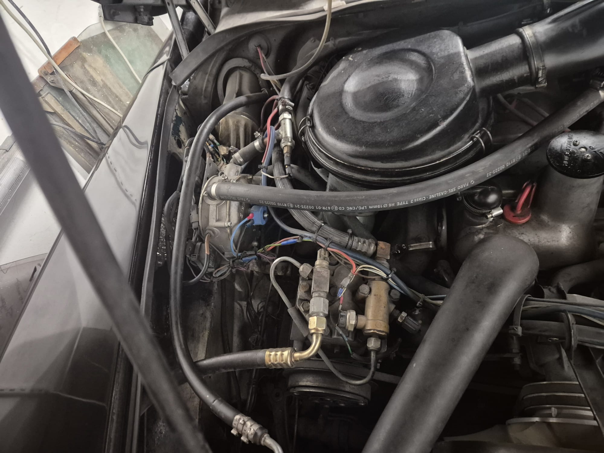
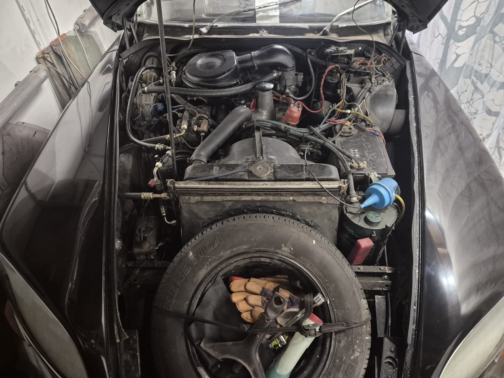
The car is equipped with its original 2.2 liter DX2 engine and the belonging 5-speed ‘long’ gearbox.
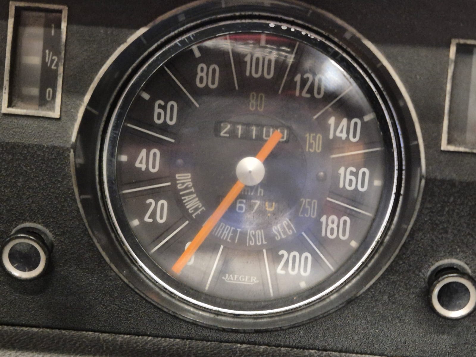
Both the enine and the 5-speed gearbox are OK to drive, and have never been overhauled. The mileage (in kilometers) is difficult to see, due to the fact that these cars’ kilometer counter rewinds at 100.000 kilometers It is likely that the car has done about 121.000 kilometers, given the state it was in when I bought it in 2006. But it might just as well have driven 321.000 kilometers. We just don/t know this for sure.
However, due to good maintenance, care and little using the car the last 30 years, the car is in good drivable state. Plus, during the rebuilding to cabrio by the ‘Oord’ coach bulding company, a lot of strengthening has been done to the car’s body, as regulations require this. The car comes with a proper Dutch Citroën ID cabrio title.
The car has always been insured and the last 10 years we drive it usually 1-4 times a year, max 100- 200 km/year
After the basic rebuild to cabrio, we got the updated car’s title as cabrio and we then have worked at the car during summers. We put on a new boot, a new roof, had the old chairs upholstered with new leather, et cetera.
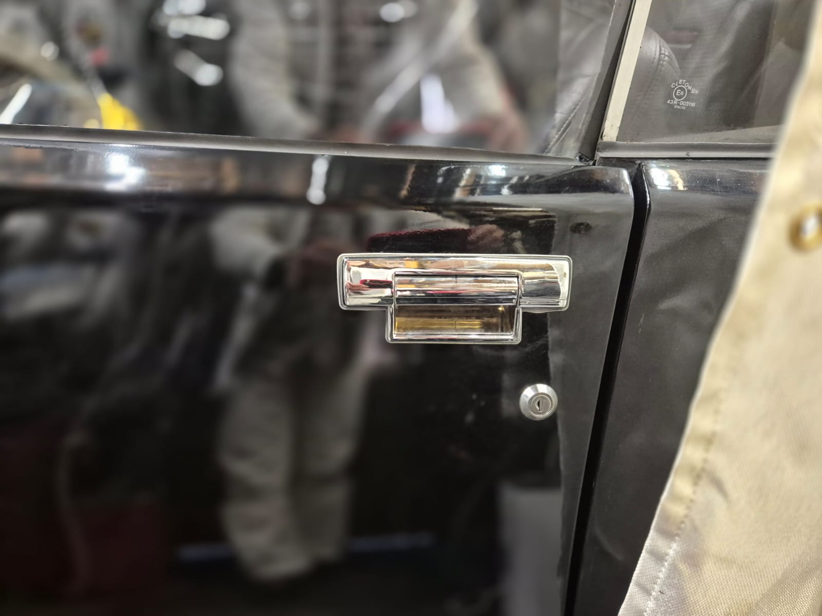
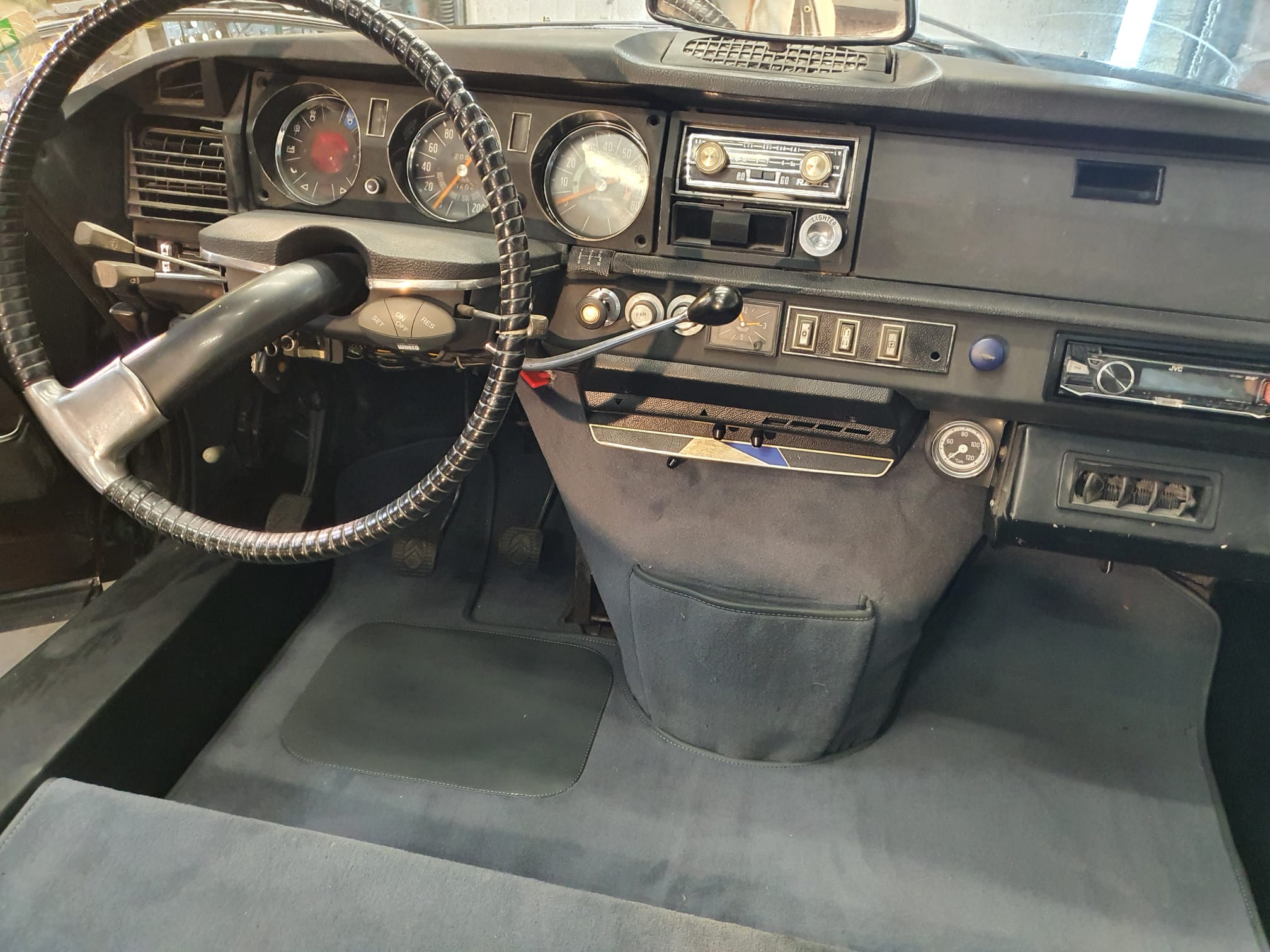
Then, finally we had the car stripped and repainted. We used NOS handlebars inside, outside, new lights, stretched rear bumper, and so on.
Finally, in 2024 we had the car’s interior upholstered.
Then the engine was checked, valves adjusted, oilfilter renewed and so on, steering rack replaced with an overhauled one, brakes overhauled, suspension overhauled, and an entirely new LPG Lovato 90kW system, including new tank and new lines and electronics has been put in to replace the old Vialle LPG system.
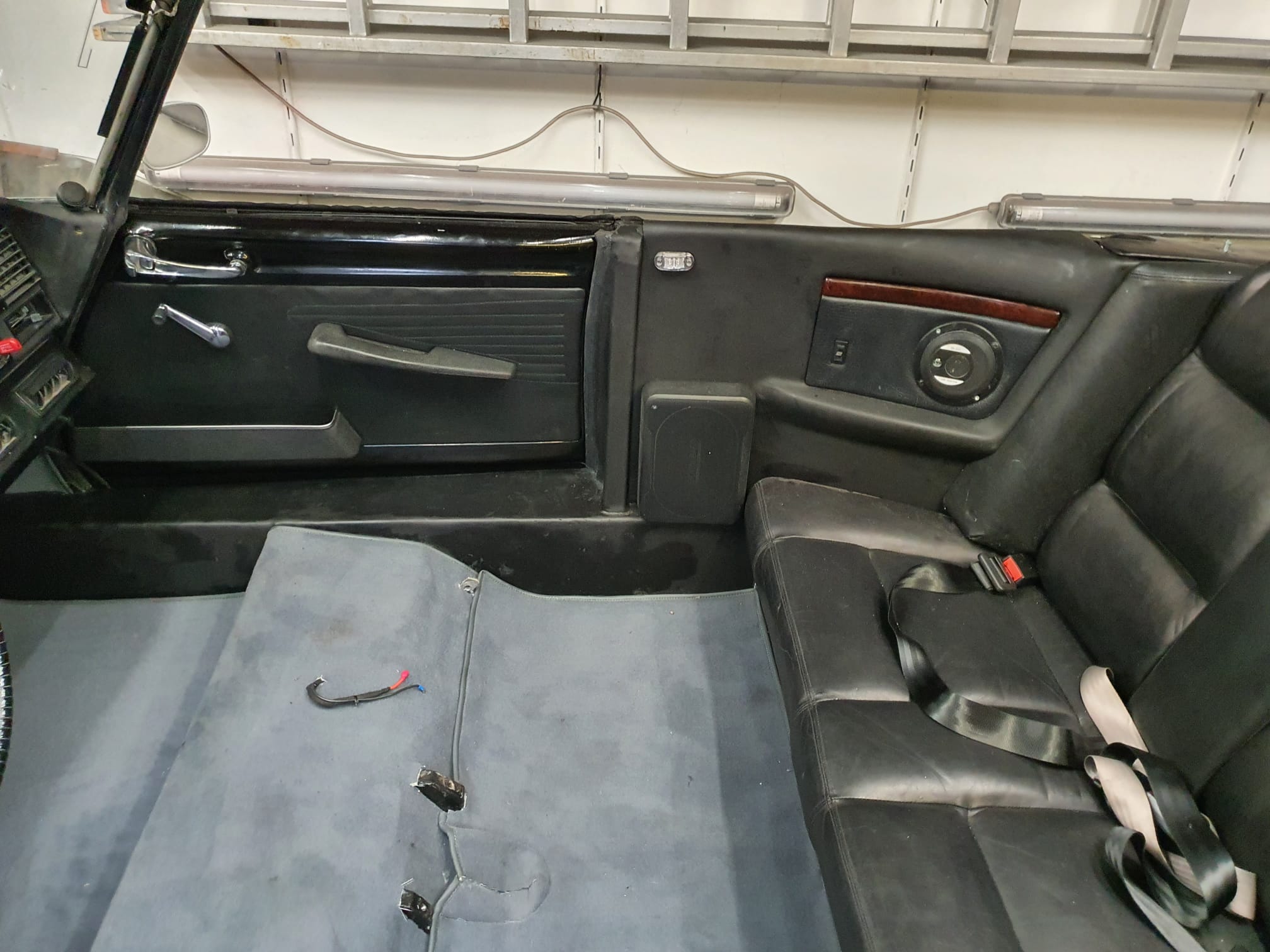
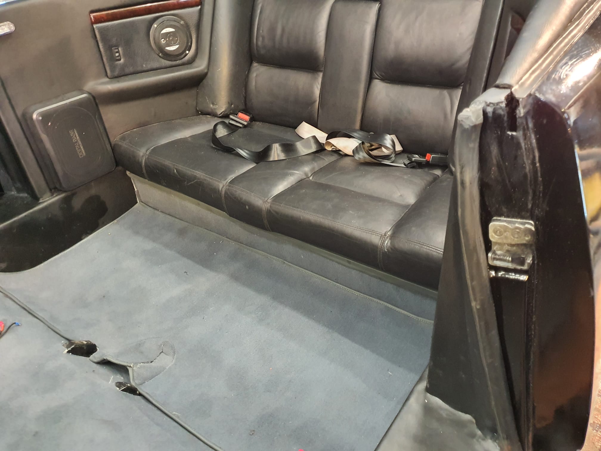
The car is fitted with 5 pieces 2-point safety belts.
And- the car is equipped with an original (in 1980’s) after-market belt-driven ‘old school’ airco system.
The system whereby the E3D tool changer determines the Z value of the four tools is fixed in the preset system files. This means that you perform a Z homing paper test for each tool to determine the deviation of each tool relative to T0, which is the leftmost tool. You enter the result in the config file as the Z-value for each tool, whereby I usually use “0” for T0 and the general Z-probe value, which I determine as the difference between the manual probe on the carriage and the nozzle height of T0.
First, you need to determine the Z deviation of T0 relative to the Z value of the carriage that picks up the tools. This is done by homing the bare carriage with a Z probe switch under the carriage to Z value = 0 on the bed.
Then you do a tool pickup from T0 and measure the height of T0 as the Z value. You then enter that value as the probe value in your config file. I find all this rather cumbersome, especially because everything changes when you change a nozzle, for example.
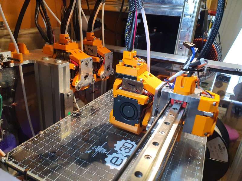
Below video: E3D toolchanger homing the carriage and do the tool pickup
DESIRED SITUATION
Ideally, I would prefer to have each of the four tools, i.e. T0 to T3, home X, Y and Z every time a new object gets printed, and in this manner you can also just select any tool to do the bed mesh.
You then take those four Z values as the Z=0 value per tool, and you’re done. This works great with the Voron that I run with TAP Z-homing! It doesn’t matter what you do with your bed or your hot end, gantry, etc. It doesn’t matter because the nozzle is used as a mechanical Z-homing tip.
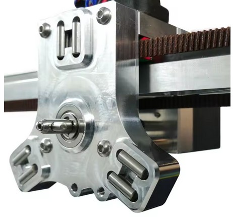
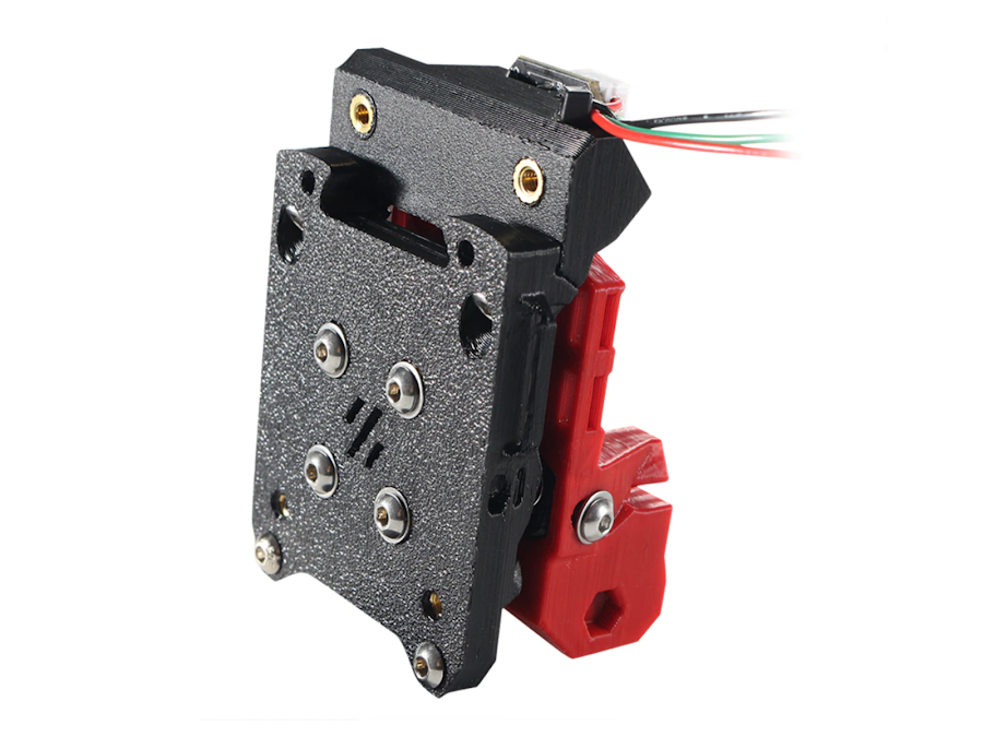
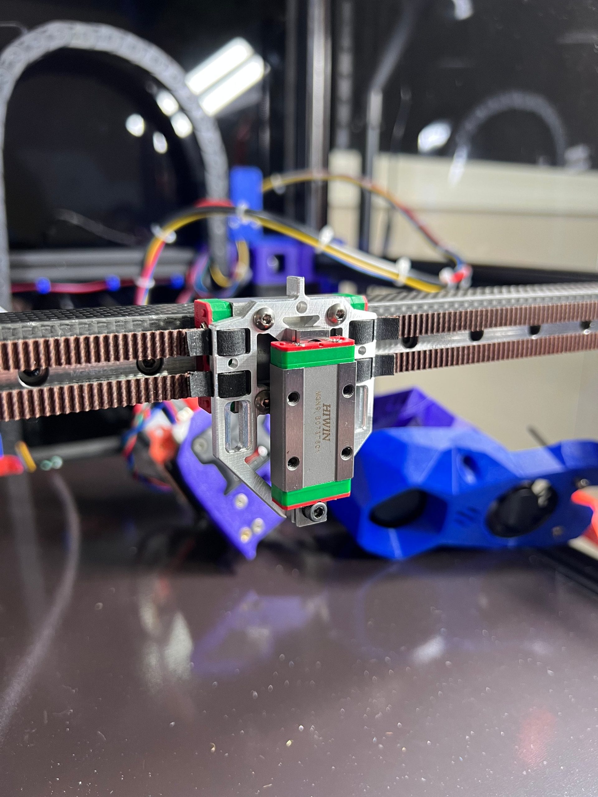
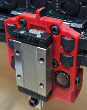
The tool pickup (the trolley) is very securely attached to the X-axis. The best solution would be to allow this entire unit to move vertically in order to enable the TAP function. That is still a challenge, partly because the A and B belts are attached to this trolley. This only seems possible with a new trolley to which the belts are attached and a separate tool changer pickup next to or in front of it. I then still need to create the TAP function between the two parts. And if the tool changer is placed in front, the X-axis must be moved back on the Y-axes. I’m not sure how that will fit….
After exploring all kinds of possibilities, this one remained: Keep the tool pickup in the same place and work with existing resources. Saw the mounting block on the X-axis slider into 3 parts and then mill 1 mm off the centre piece on both mounting sides. Adjust the side plates to which the belts are attached so that these plates can be reattached to the middle section of the slider block with new countersunk screws. The through bushings on the bottom no longer pass through the plate, and the plate must be milled away at the corners, just like on the top, to create approximately 5 mm of vertical play. Mount the two lower connection points of both side parts with two 1 mm spacer rings each so that the carriage can move up and down and the sides remain at the original distance from each other in order to maintain the stability of the moving construction. An additional mounting block for the vertical linear rail of the TAP slider is placed on the centre mounting block of the X-axis slider. Extension pieces are attached to the front and/or rear of the tool pickup, to which the TAP slider with the moving part is attached so that everything can move up and down by approx. 3-4 mm..
How the TAP function works on a Voron2.4 3D printer
ADDITIONAL: Self-searching tool changer
And while I’m at it: why not make a self-searching tool changer? Roughly set it up with the XYZ coordinates per tool, the last part electronically with a guide system between the pick-up trolley and the tool, and the final fitting with the existing mechanical fitting.
Instead of determining exactly where each tool should be picked up and put away by trial and error, you could use an electronic guidance system to aim precisely at the right tool when it needs to be changed. No more hassle with X-Y settings and homing axes. Because if anything changes as a result of mechanical stress in the frame or due to small deviations from the X and Y homing, picking up and putting away tools will regularly go wrong.
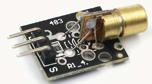
One possible way to do this could be a passage LED/LASER system, such as those used at shop entrances.
.
mini focussable laser module
mini laser receiver module
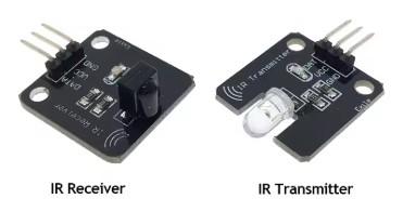
Or simply use infrared, which is invisible but also much less dangerous.
To do this, you use a targeting laser, such as in a levelling system, or an infrared laser with a receiver.
This is placed on top of the X-axis on the moving toolhead and is aimed at the tools, at a 90-degree angle to the X-axis.
You then activate the correct tool you want to move to or pick up as the receiver.
With an X-sweep movement, you can make contact with the receiving tool and then move in a straight line towards the tool until you reach the pick-up point, which is specified in absolute Y value in the configuration file. Sounds like a great development!
ADDITIONAL: Precise XYZ homing of the tools
And I would like to have a way to centre X, Y and Z of each tool nozzle in detail relative to the other tool nozzles, just like with my CNC machines:
With such a head alignment block, you can accurately determine the position of all axes on a CNC machine. First, you need to determine the approximate position of this block, with an accuracy of approximately 1 mm on the X and Y axes.
The alignment block is electrically insulated and works by making contact between the tool tip and the block.
How does homing with an alignment block work?
You programme a centring macro in G-code.
First, you temporarily set the motor power to the lowest possible value to avoid damage if anything is in the way of the moves to be made.
Just as when I regularly do a home-all, with this new method you also set the bed and the relevant tool nozzle to operating mode (e.g. bed at 70 degrees and nozzle at 180 degrees).
Then you do a normal XY homing, which in my case works with limit switches (or optical switches) at the start of the X and Y axes.
A Z-homing action is also necessary unless you do not want to remove the Z-move block that occurs when you have not first homed Z.
Then move the Z-axis up sufficiently to avoid hitting the block.
Next, move to the absolute XY position of the block.
When you are above the block with your tool, home your Z.
Then home on Z+0.3 both -X and +X, and in the middle of -X and +X home -Y and +Y.
The result is the exact position of the centre on the flat Z plane of the alignment block.
Because you know exactly what the position is in relation to the bed centre and from X0, Y0 and Z0, you can translate this directly into the macro and enter the Z0, X0 and Y0 values as absolute values.
It should be possible to home the E3D tool changer tools in this way as well, with Z using the TAP function and X and Y using electrical detection as described above for the CNC milling machines. We will see if and how this will work as a supplement to TAP-Z homing with the current X and Y microswitch homing on the X and Y axes.
CONCLUSION -FOR NOW-
The credo still seems to be: If the E3D tool changer is working, it’s best to leave it alone. That doesn’t suit me at all, because I often move my printers around. And that doesn’t always go well.
So I’m going to look into these issues and, if possible, build something!
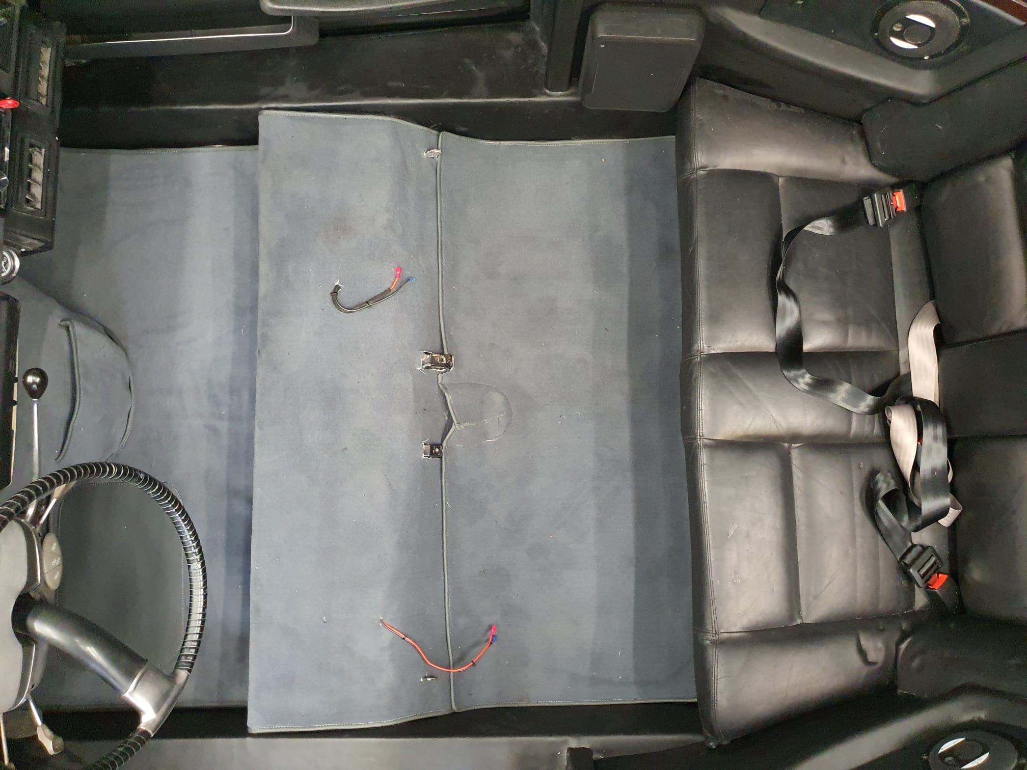
After all the external and internal technical finishing was done, I applied the gray upholstery in the car today.
The exterior had been ready for a while, yet it still took a few weeks to get the interior ready in every detail as well.
The details:
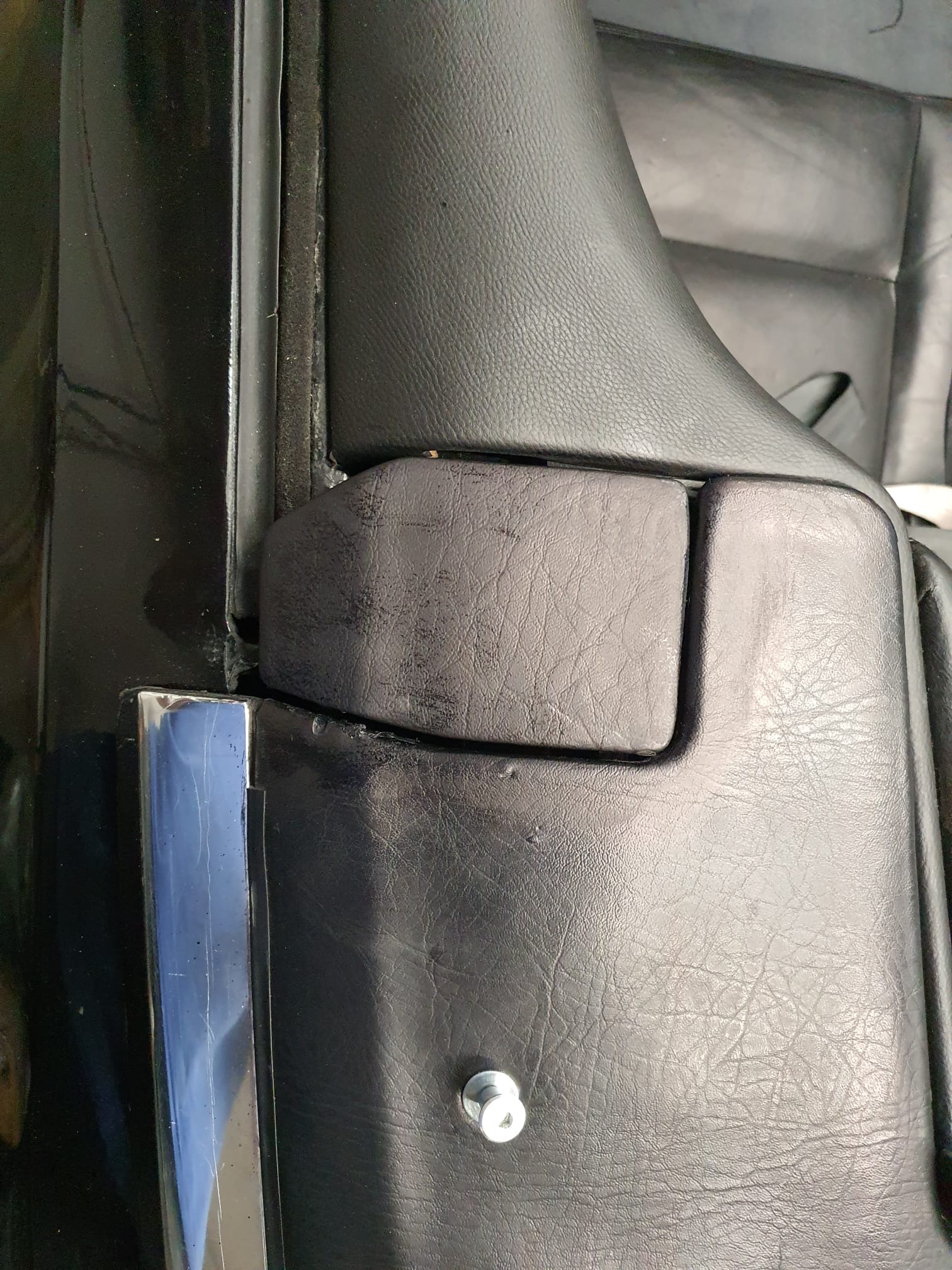
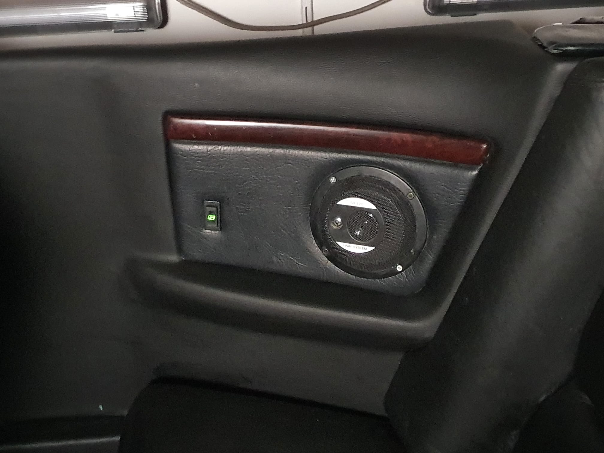
Still working on some minor stuff like: a) DONE: upholstering the top of the front window’s frame & the A-pillar’s inside and b) DONE: cleaning the dash better, c) cleaning the engine bay, d) fitting the detachable pulling rod, e) DONE: gluing the upholstering of the roof’s hood, f) DONE: Placing the Pioneer subwoofer to the right side under the dash, g) Placing new seals on the valve stems (maintenance precaution), h) Ordered and received: Replacing the gas dampeners of the roof frame, i) Processing: Polishing the car.
Please donate $1 to my paypal account if you use (parts of) my developed materials so I can continue to share nice stuff for you to download
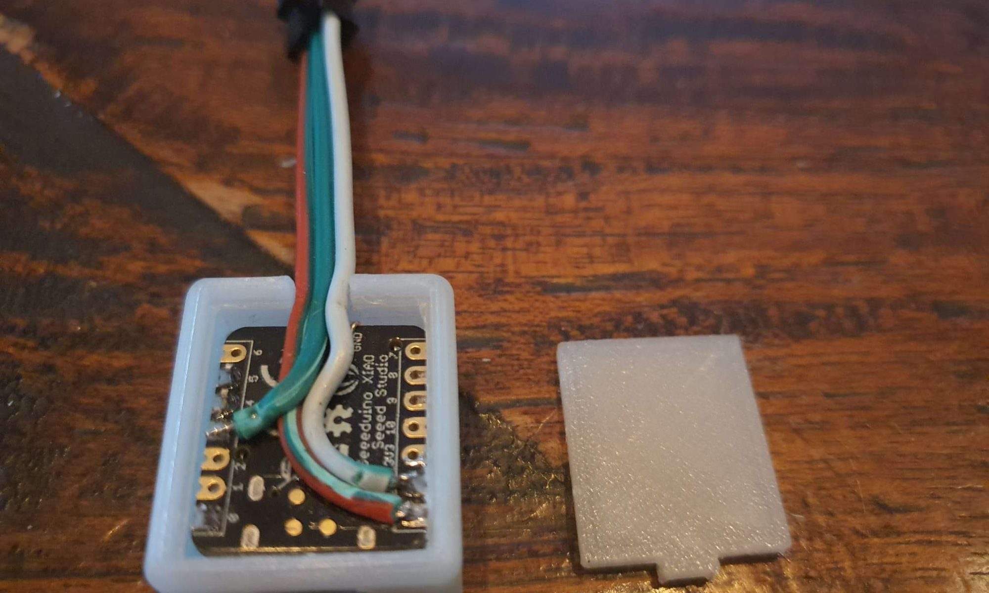
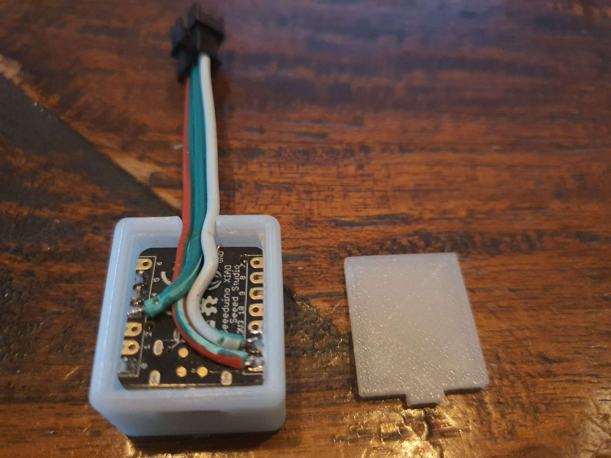
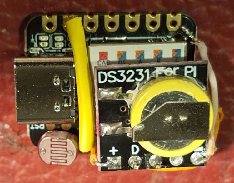
I also added a mini board with a clock chip, DS3231 to the XIAO USB-C board, and an LDR to make the RGB’s brighter when they are used during daylight conditions. An example Arduino code with clock function is HERE.
The LDR is mounted, the clock board is not yet mounted. A clock board is only required if you want to use the clock functions. Using an LDR is highly recommended.
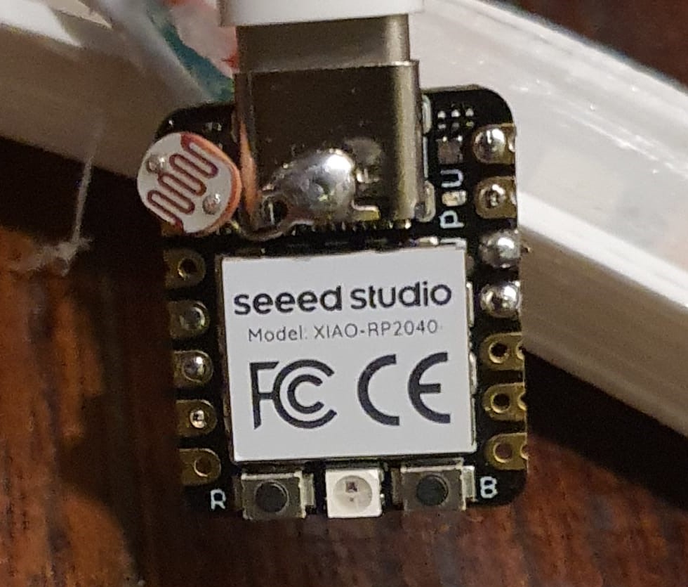
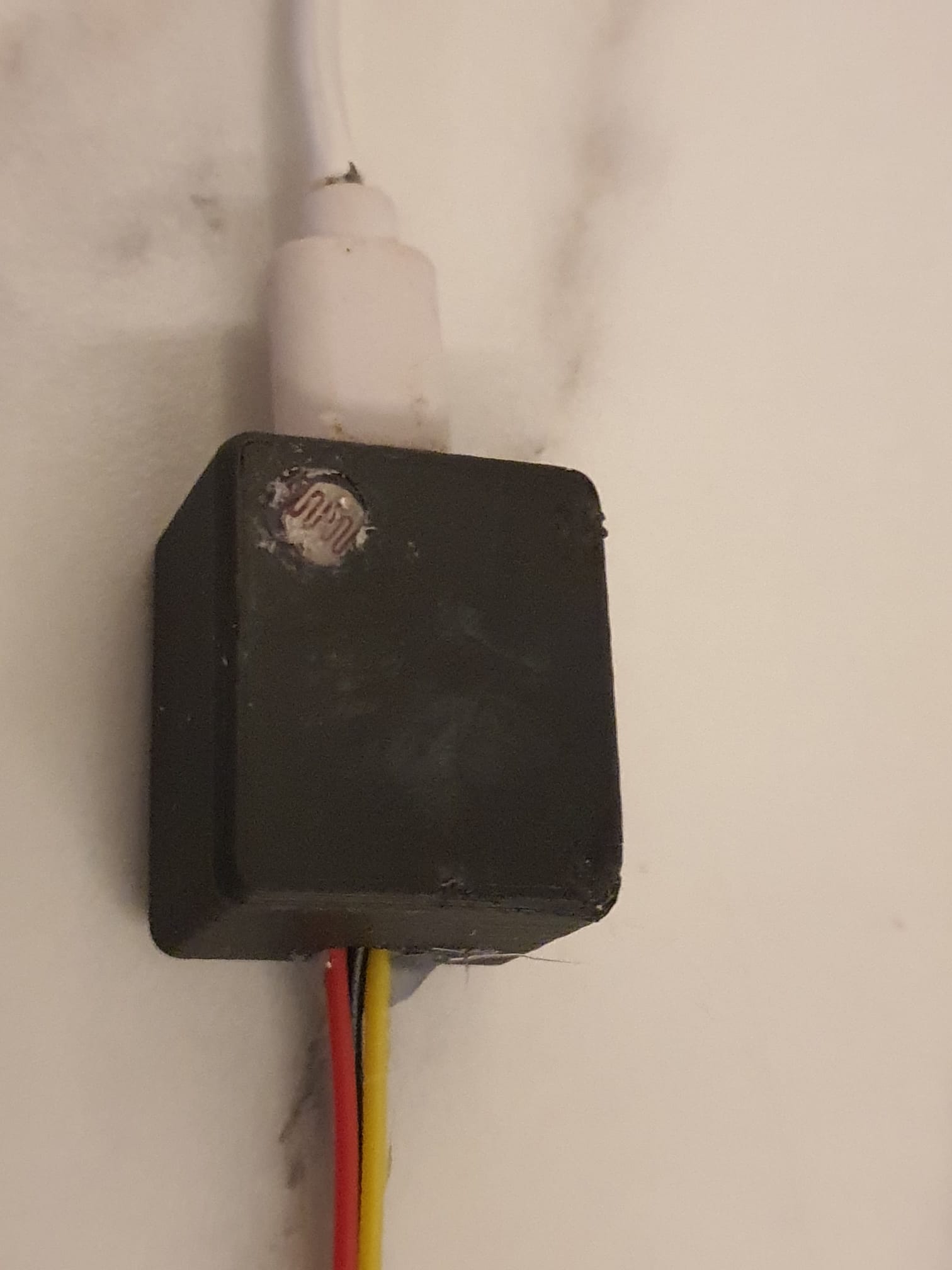
The LDR is mounted on the XIAO board’s top on A0 and GND, so it can be flush to the outer skin of the case through the dedicated LDR hole. Be aware to also add a 10K resistor between A0 and 3v3 since this board does not have programmable PULL-UP resistors.
The mini DS3231 clock board is connected to the XIAO’s pins A4 and A5, 3V3 and GND. There is also a small battery on the little clock board., so the time will always be available. I mounted the clock board so that the DS3231 chip is flat against the RP2040 chip. Then, the Data in and out of the clock board are then facing D4 and D5 of the RP2040. I used 2 Arduino pin headers to connect these data lines together. 3V3 aand GND are connected between the boards using thin wires.
Output to the LED’s is on pin 3 (D3). For the LEDS, also VCC and GND are required, either from the XIAO board’s VCC and GND pins or from the board’s 5V power supply +5V and GND connections. The LDR is mounted making use of a little stud, cut off from the tiny clock board since they have to be removed from the clock board anyway. This makes the LDR fit the box’s LDR hole perfectly.
For resetting an DR2040, a small hole is made to reach the little BOOT switch. This is sometimes required since the RP2040 can get bricked when a non-working void is uploaded. Push the boot butten when powering up, release the button and the RP2040 is in recovery status. Up[load a simple program and the RP2040 will resume normal functioning. Then, the normal COM port will work again an normal flashing is again possible.
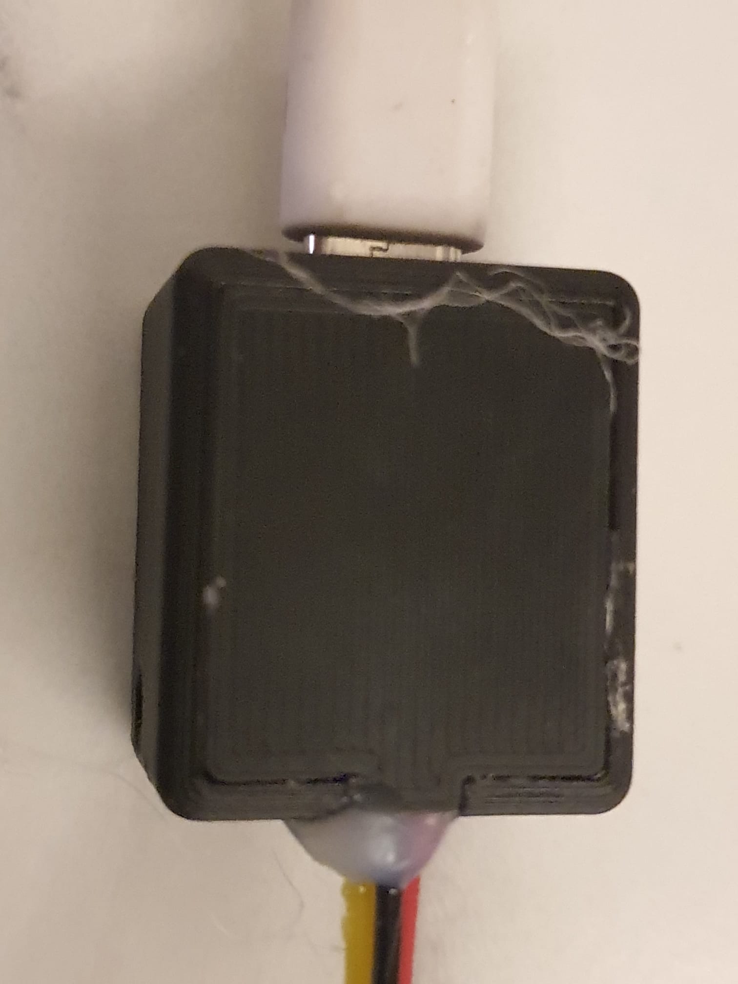
The case has a snap-on lid that will also fixate the outlet cable for the RGB LED’s.
Please donate $1 to my paypal account if you use (parts of) my developed materials so I can continue to share nice stuff for you to download
After I installed the homing switches for X and Y on the E3D toolchanger, I finally had a decent starting point to get the tools pickup and parking tuned.
Originally, I used sensorless homing but this caused changing offset values of the X- and Y positions of the machine. So the tools could not be picked up or brought home consistently after a reset.
Now, everything works fine and the X-Y values don’t change anymore after a reset.
What I did was to first make some macros for a one-off setting of the X and Y postion of the 4 Tools for the toolhead’s positioning. If you don’t do this, you have to change all X values manually in 8 macro’s every time you want to change the value of X.
This was done with a number of global variables. After defining these in a macro, they need to be called before using them. In Config.g, I made a reference to run the macro of the globals.g macro so it runs every time you boot the Duet.
In config.g, after the Tool definitions I added the M98 code to start the global definition of the used variables:
M98 P”0:/sys/globals.g” ; Make global variables in this globals.g macro
This macro file looks like this in my case and please be aware that the actual variables will differ per machine, but this may give you a starting point:
global T0_X_dock=-12.3 ; X-Parking position of Tool 0
global T0_Y_dock=225.2 ; Y-Parking position of Tool 0
global T1_X_dock=80 ; X-Parking position of Tool 1
global T1_Y_dock=225.9 ; Y-Parking position of Tool 1
global T2_X_dock=212 ; X-Parking position of Tool 2
global T2_Y_dock=226 ; Y-Parking position of Tool 2
global T3_X_dock=304.7 ; X-Parking position of Tool 3
global T3_Y_dock=225.4 ; Y-Parking position of Tool 3
The tfree 1-3and the tpre 1-3 files will then be like this for T0, and you can make the others by just fulling in T1 , T2 or T3 where it now states T0:
; tpre0.g
; called before tool 0 is selected
;Unlock Coupler
M98 P”Coupler – Unlock.g”
;Move to location
G1 X{global.T0_X_dock} Y200 F50000 ; was X-10.5
;Move in
G1 X{global.T0_X_dock} Y220 F50000
;Collect
;G1 X{global.T0_X_dock} Y229.2 F1000 ;was f2500
G1 Y{global.T0_Y_dock} F1000
;Close Coupler
M98 P”Coupler – Lock.g”
;WARNING! WARNING! WARNING! WARNING! WARNING! WARNING! WARNING! WARNING! WARNING! WARNING! WARNING! WARNING!
;if you are using non-standard length hotends ensure the bed is lowered enough BEFORE undocking the tool!
G91
G1 Z10 F1000
G90
;Move Out
G1 X{global.T0_X_dock} Y150 F10000; was 4000
And I made some macros for checking where the toolhead is positioned, right in front of the tools T0-T3:
; fit_T0.g
; called to fit the Tool just in front of the dock
G91
G1 Z4 F1000
G1 Y-10 F2000
G90
G53 G1 X150 Y100 F20000
;Move In
G53 G1 X{global.T0_X_dock} Y150 F10000
G53 G1 X{global.T0_X_dock} Y200 F10000
G53 G1 X{global.T0_X_dock} Y220 F10000
If you want to check wether you made the correct changes to globals.g, be aware that the new values in the globals.g variables macro will only be read when you reboot. [If you want to redefine the values in any other way without rebooting, you will need another type of call function.]
My E3D toolchanger appeared to have some small inconsistencies in homing X and Y.
This became apparant after I tried to tune the exact positions of the tools pickup, after having homed.
Every time it was tuned, it worked well and the next day it was just a bit off. Then I retuned it again, and after a day it was off again. Not a lot, but just 0.1 mm or a bit more. But it did cause problems with the toolchanges.
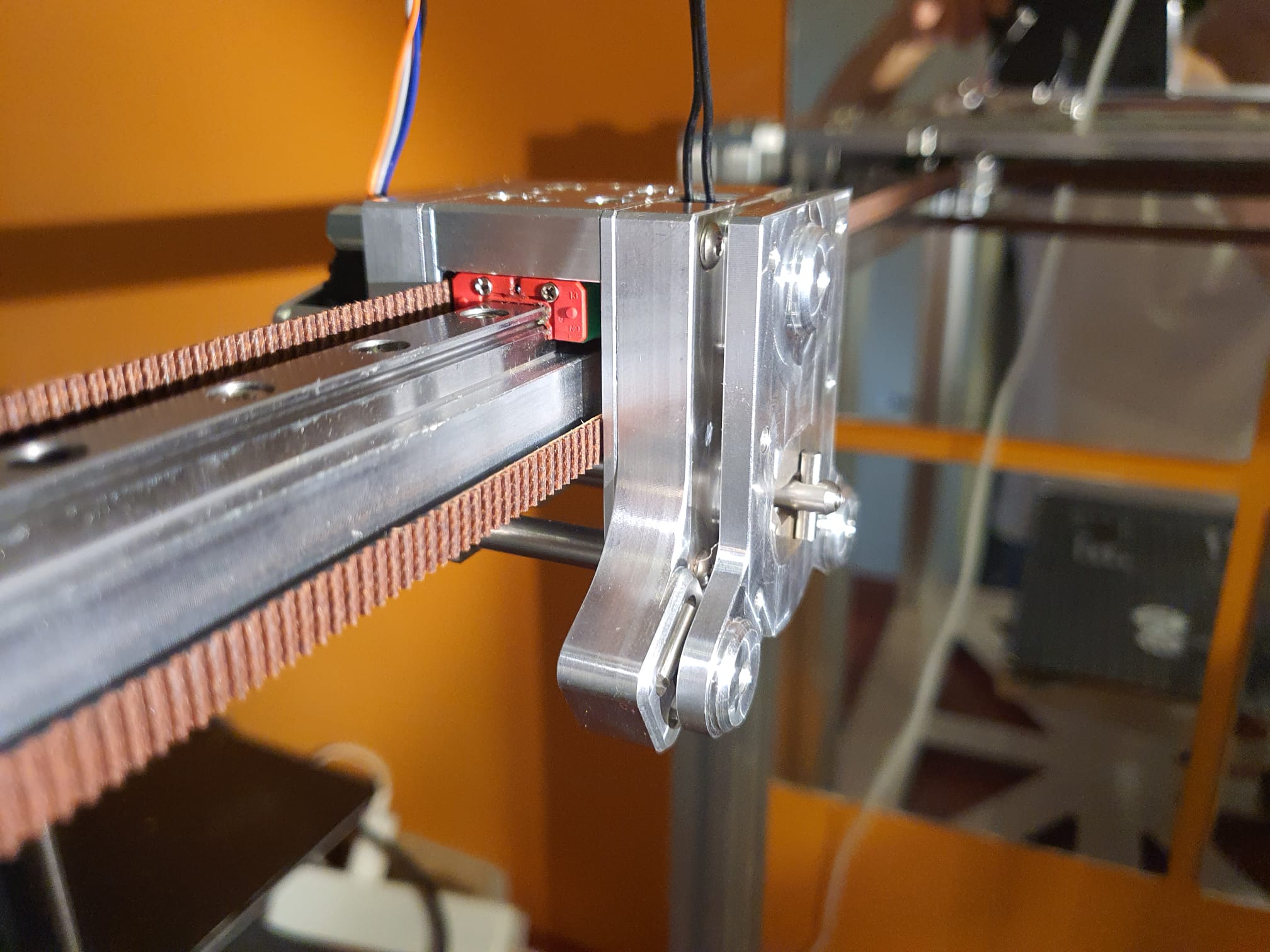
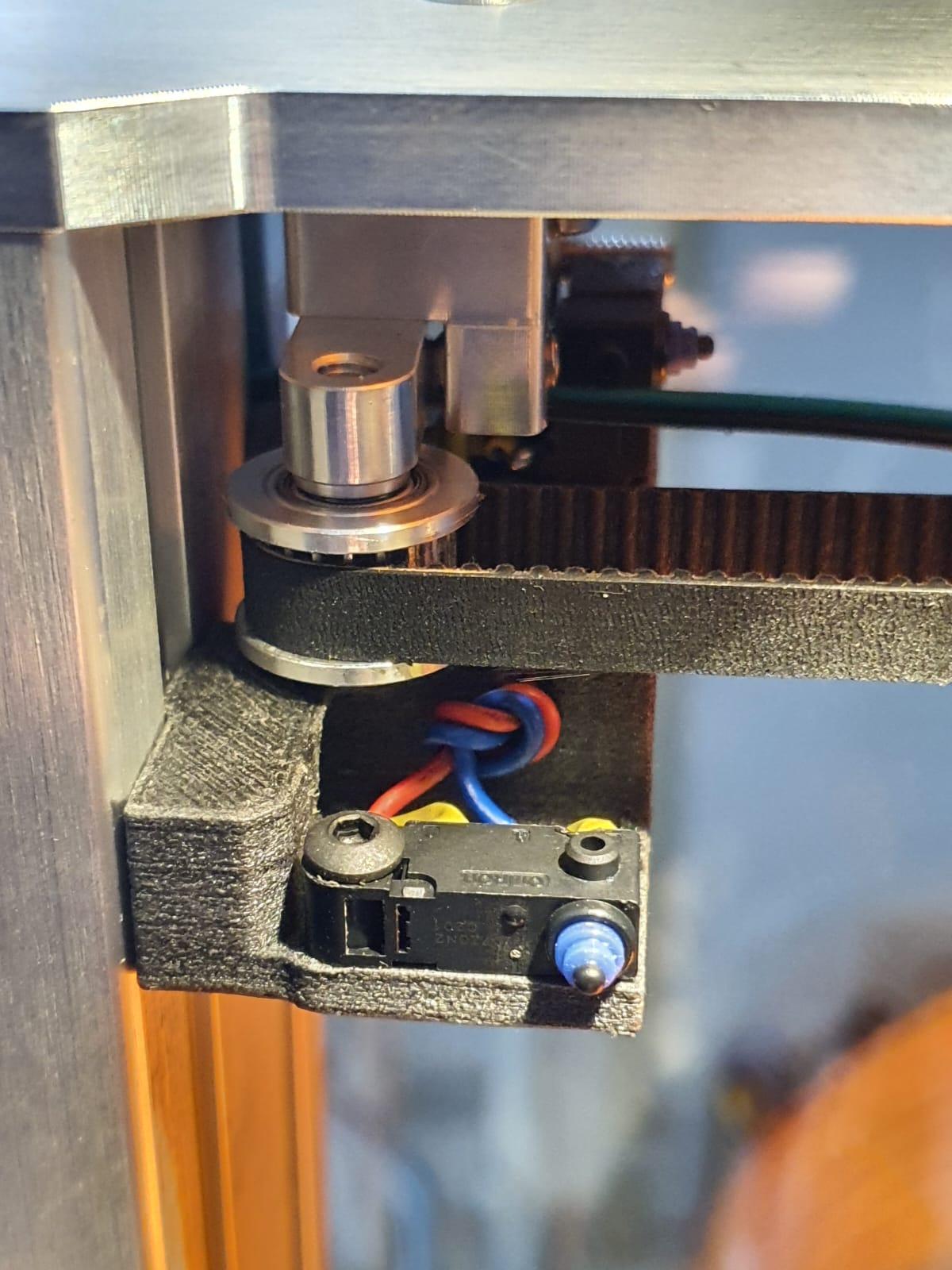
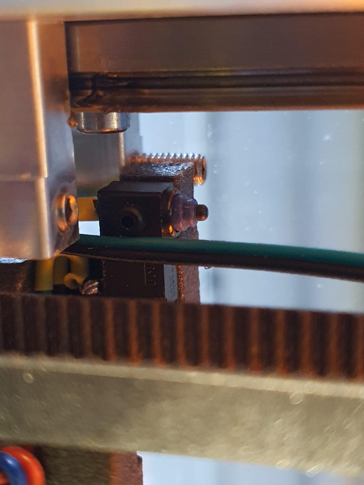
So- after reading a bit I found that others had this problem as well and produced a solution: Just put in a couple of good X- and Y homing switches!
I even found the to be printed 3d-parts for mounting these switches. Thanx for this, folks!
The switches are the same type as for the Z-switch.
X-axis end switch
Y-axis end switch
I printed the mounts in PETG carbon on my Prusa mini and mounted both switches on the E3D toolchanger.
After this, I amended config. g and the homing files, please see the rest of my post for this:
CONFIG.G CHANGES
; Endstops
M574 X1 S1 P”xstop” ; X min active high endstop switch
M574 Y1 S1 P”ystop” ; Y min active high endstop switch
M574 C0 ; no C endstop
M574 Z0 P”nil” ; no Z endstop switch, free up Z endstop input as Z endstop switch. (I changed this part for correct working with RRF3.3+)
NEW HOMING FILES:
; homex.g
; called to home the x axis
M98 P”homey.g” ; Home Y always before homing X
G91 ; use relative positioning
G1 H2 Z3 F5000 ; lift Z 3mm
G1 H1 X-400 F15000 ; move left 400mm, stopping at the endstop
G1 X5 F15000 ; move away from end
G1 H1 X-400 F2000 ; move left 400mm, stopping at the endstop
G1 X2 F2000 ; move away from end
G1 H2 Z-3 F1200 ; lower Z
G90 ; back to absolute positioning
; homeall.g
; called to home all axes;
M98 P”homec.g” ; Home C (ToolHead)
M98 P”homex.g” ; Home X
M98 P”homez.g” ; Home Z
G1 X150 Y-49 Z20 F15000 ; Park
; homey.g
; called to home the Y axis
G91 ; use relative positioning
G1 H2 Z3 F5000 ; lift Z 3mm BED DOWN
G1 H1 Y-400 F15000 ; move to the front 400mm, stopping at the endstop
G1 Y5 F15000 ; move away from end
G1 H1 Y-400 F2000 ; move to the front 400mm, stopping at the endstop
G1 Y2 F2000 ; move away from end
G1 H2 Z-3 F1200 ; move Z BED UP
G90 ; back to absolute positioning
Z homing did not change and remains as is:
; homez.g
; called to home the Z axis
M98 P”Coupler – Unlock.g” ; Open Coupler
G91 ; Relative mode
G1 H2 Z5 F5000 ; Lower the bed
G90 ; back to absolute positioning
G1 X150 Y100 F50000 ; Position the endstop above the bed centre
M558 F1000 ; speed to 1000
G30 ; probe x 1
M558 F300 ; speed to 300
G30 ; probe x 1
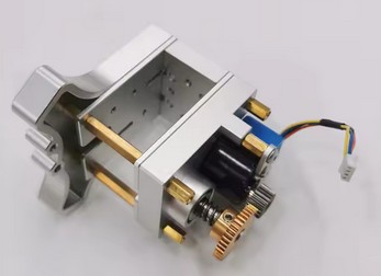
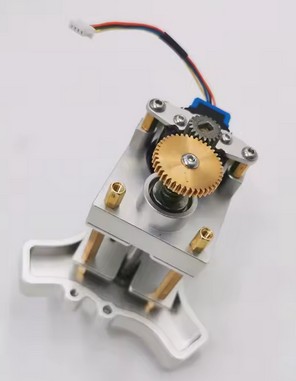
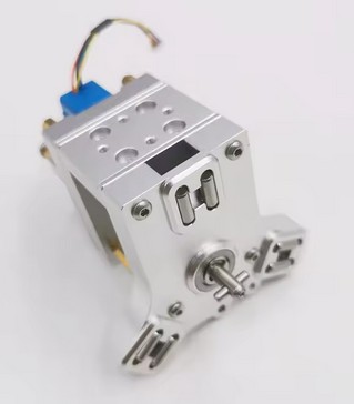
The toolhead stepper of my E3D toolchanger system suddenly broke down.
The cause was a failed tool pickup move, due to which the rotating axle of the toolhead pickup system got blocked.
After exchanging the stepper I changed the Duet’s settings so the C-drive will not be able to generate too much torque.
This will prevent the last teethed wheel to break whenever the driven pickup axle gets blocked under extreme circumstances.
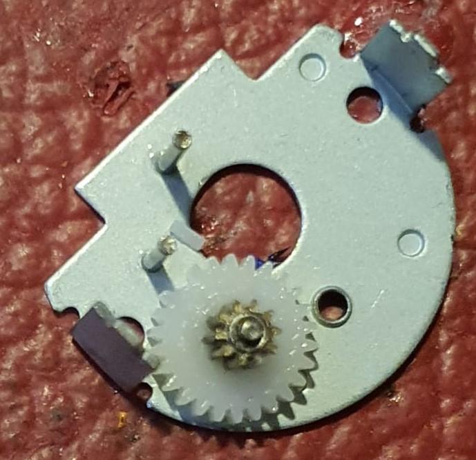
After opening the case of the failed reduction box, I discovered 1 broken tooth of the final gear.
I ordered me a new one, and mounted this. And I changed the C-drive’s settings to make use of the stall mechanism. It took some tweaking to get this to work properly. After all, picking up a tool must still work as this is the base intention.
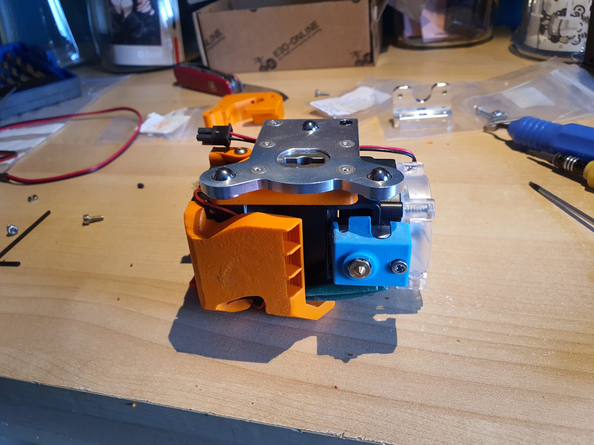
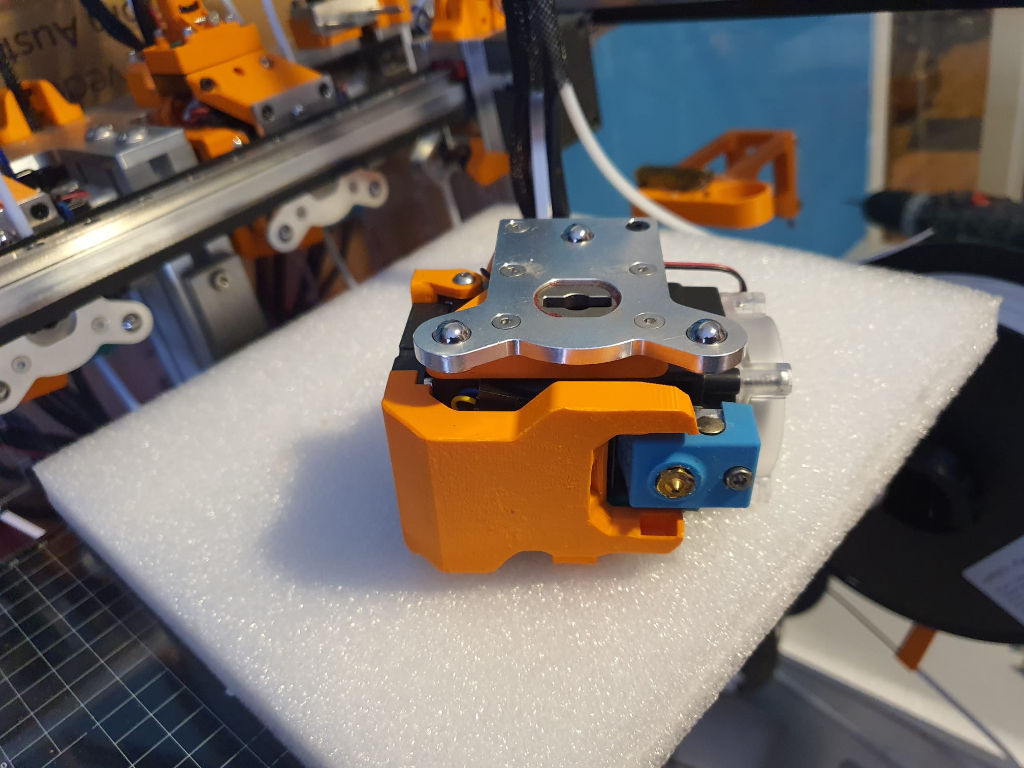
In the end, the solution to my intermittent on/off problem with my toolfans on the Hymera direct drives was extremely simple.
The picture shows the solution, as the Hymera stepper driver obviously interferes with the 40mm fans. The problem was that these fans 2,4,6 and 8 not always started spinning.
I tried to exchange the fans which did not help, tested the Voltage, current , settings and so on. Everything appeared to be OK.
Strangely enough, when testing the fan off the Hymera tool, even including the duct attached, everything woked fine. Just did not work when mounted on the Hymera.
Finally, Just trying some things, I pushed a thin steel plate (NOT RVS) in between the fan and the stepper motor, and now it always works, even at 5% PWM! Problem solved!
After testing at all tools, I made 4 better fitting thin plates and mounted these at the 4 tools and no problem exists anymore, ever since!